Journal of Power Sources 140 (2005) 346–349
Short communication
Evaluation of PEMFC power systems for UPS base station applications
夽
M. Lin
a,∗, Y. Cheng
b, M. Lin
c, S. Yen
daTatung Company/System Technologies Inc., Taipei, Taiwan bTaiwan Insitute of Economic Research, Taipei, Taiwan
cAcbel Polytech Inc., Taipei, Taiwan dNational Taiwan University, Taipei, Taiwan
Received 1 August 2004; accepted 20 August 2004
Abstract
For UPS applications such as the mobile phone base station, the selection of PEM fuel cell technology seems only feasible for the case of a heavy-duty service time requirement. The weight reduction of the whole energy system using fuel cell technology is significant, and the volume and the cost can also be superior when the service time is over 24 h. If the production cost and the module volume of fuel cell system can be further reduced, the results will be more promising.
© 2004 Published by Elsevier B.V.
Keywords: PEMFC; UPS applications; Base station
1. Introduction
The commercial progress of fuel cell technologies is ap-proaching a critical point, and lots of developers are eager to look for the initial niche market. One of uses may be the application to UPS such as a mobile phone base station[1,2]. According to the present situation in Taiwan, there are over 25,000 base stations constructed by six local telecom com-panies. Due to typhoons, earthquakes, and floods which fre-quently happen in Taiwan, interruptions of electricity supply are a severe threat to uninterrupted service of mobile phones. Telecom companies usually use lead-acid batteries to extend service time during blackout periods. However, some limita-tions of volume, weight, and cost are considered for this UPS application. Apparently, it would not be practical to extend the UPS service time from currently 2 or 4 h to 8 h, or even
夽 Presented at 2004 Fuel Cell Seminar, San Antonio, TX, USA, 1–5 November, 2004.
∗Corresponding author. Tel.: +886 2 25925252x2647; fax: +886 2 25948201.
E-mail address: m.h.lin@tatung.com (M. Lin).
24 h. Thus, PEMFC power generators may be an interesting option for heavy-duty UPS applications.
In order to understand the effects of device cost, module weight, module volume and energy expense, comparisons and analysis of conventional lead-acid battery units and pro-posed PEMFC power generating systems for the UPS ap-plication in the case of base station has been illustrated and evaluated in this study.
2. System descriptions and data collection
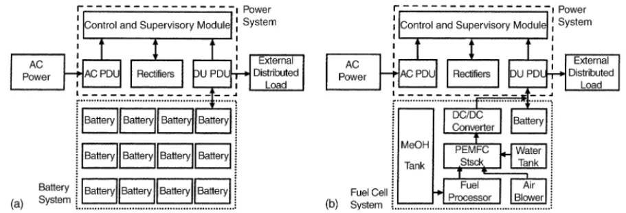
A standard online energy system used in the mobile phone base station consists of switching mold rectifiers, control and supervisory module, ac and dc power distribution units, bat-tery management, and low voltage disconnect switch options
[3,4]. As shown inFig. 1(a), a conventional model adopts lead-acid battery packs for supplying electricity during a blackout period. If the runtime of a base station needs to be extended, then the battery system should be enlarged. In the proposed fuel cell model as depicted inFig. 1(b), a PEMFC
0378-7753/$ – see front matter © 2004 Published by Elsevier B.V. doi:10.1016/j.jpowsour.2004.08.033
M. Lin et al. / Journal of Power Sources 140 (2005) 346–349 347
Fig. 1. Simplified schematic diagrams of the energy system used in mobile phone base stations: (a) conventional battery model; (b) fuel cell model. Table 1
Estimation of the production cost of PEM fuel cell power generating system integrated with methanol reformer and dc/dc converter
Production quantity (pc year−1)
1–5 50 1,000 10,000
2 kW PEMFC stack (US$) 11,642 7,463 2,985 1,493 MeOH reformer (US$) 26,866 19,403 10,448 5,970
BOP (US$) 7,761 5,970 3,582 2,388
dc/dc converter (US$) 358 269 209 149
Total cost (US$) 46,627 33,105 17,224 10,000
power generating system fueled by methanol is used instead of the battery system, and the runtime of a base station will depend on the volume of fuel tank.
A typical energy system for the base station can be as-sumed to have 2 kW nominal capacity and 2.5 kW peak ca-pacity. In addition, the runtime of the energy system in the blackout period for this study will be extended from stan-dard 2 h to 4, 8, 12, and 24 h. With the intention to analyse the difference between battery models and fuel cell models, the data corresponding to weight, volume, cost and
perfor-Table 2
Calculated results of device cost, module weight, module volume and energy expense of lead-acid battery systems used in the mobile phone base station Service time 2 h 4 h 8 h 12 h 24 h Power system (kg) 61 61 61 61 61 Battery number 4× 1 4× 2 4× 4 4× 6 4× 12 Battery system (kg) 143 286 573 859 1,718 Rack (kg) 50 70 100 170 300 Total weight (kg) 294 417 734 1,090 2,079
Power system (US$) 4,600 4,600 4,600 4,600 4,600
Battery system (US$) 800 1,600 3,200 4,800 9,600
Rack (US$) 200 275 350 625 1,050
Total cost (US$) 5,600 6,475 8,150 10,025 15,250
Dimension (m) 0.6× 0.6 × 0.9 0.6× 0.6 × 1.2 0.6× 0.6 × 1.8 0.6× 0.6 × 3.0 0.6× 0.6 × 5.4
Volume (m3) 0.324 0.432 0.648 1.000 1.944
Electricity cost (US$) 0.4 0.8 1.6 2.4 4.8
mance of each component is collected. Most of the data about power systems and batteries were obtained from Acbel Poly-tech Inc., and the counterparts about fuel cell systems have been provided by Tatung Company.
Due to the fuel cell system not being a commercially vi-able product, the production cost absolutely depends on the customer’s purchasing quantity. Estimated costs of 2 kW fuel cell systems for various production quantities are listed in
Table 1. The production cost will be as high as US$ 46,627 for a small quantity, and reduce to US$ 10,000 for 10,000 units. Unlike the case of a large capacity fuel cell system, the reformer seems to be the most expensive component in a 2 kW system. Also, the costs of small and special BOP com-ponents are quite expensive, even more than those of fuel cell stacks in mass production.
3. Results and discussions
The calculated results about device cost, module weight, module volume and energy expense of lead-acid battery mod-els for 2, 4, 8, 12, and 24 h service time are shown inTable 2,
348 M. Lin et al. / Journal of Power Sources 140 (2005) 346–349
Table 3
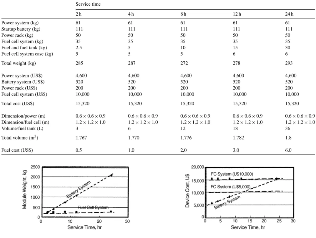
Calculated results of device cost, module weight, module volume and energy expense of PEM fuel cell systems used in the mobile phone base station Service time
2 h 4 h 8 h 12 h 24 h
Power system (kg) 61 61 61 61 61
Startup battery (kg) 111 111 111 111 111
Power rack (kg) 50 50 50 50 50
Fuel cell system (kg) 35 35 35 35 35
Fuel and fuel tank (kg) 2.5 5 10 15 30
Fuel cell system case (kg) 5 5 5 6 6
Total weight (kg) 285 287 272 278 293
Power system (US$) 4,600 4,600 4,600 4,600 4,600
Battery system (US$) 520 520 520 520 520
Power rack (US$) 200 200 200 200 200
Fuel cell system (US$) 10,000 10,000 10,000 10,000 10,000
Total cost (US$) 15,320 15,320 15,320 15,320 15,320
Dimension/power (m) 0.6× 0.6 × 0.9 0.6× 0.6 × 0.9 0.6× 0.6 × 0.9 0.6× 0.6 × 0.9 0.6× 0.6 × 0.9 Dimension/fuel cell (m) 1.2× 1.2 × 1.0 1.2× 1.2 × 1.0 1.2× 1.2 × 1.0 1.2× 1.2 × 1.0 1.2× 1.2 × 1.0
Volume/fuel tank (L) 3 6 12 18 36
Total volume (m3) 1.767 1.770 1.776 1.782 1.8
Fuel cost (US$) 0.5 1.0 2.0 3.0 6.0
Fig. 2. The variation of module weight of energy systems vs. service time.
and the counterparts for fuel cell models are compiled in
Table 3.
As shown inTable 2, the weight of a battery model mainly comes from lead-acid batteries. The total weight of whole en-ergy system is 254 kg for 2 h of service time during blackout period, and will rapidly rise to 2079 kg for 24 h. In the case of the fuel cell model, the startup time of the reformer is approximately 30 min, thus auxiliary batteries should be
in-Fig. 3. The variation of module volume of energy systems vs. service time.
Fig. 4. The variation of device cost of energy systems vs. service time.
stalled to supply electricity before the fuel cell system can take over. As shown inTable 3, the weight of power system, startup batteries and power rack is 222 kg, and the weight of a 2 kW PEMFC power generating system is 35 kg. Both power and fuel cell systems are the same for various condi-tions of service time requirements, and only the weight of fuel and fuel tank will be a little different. InFig. 2, the total weights of two energy systems are compared, and the weight
M. Lin et al. / Journal of Power Sources 140 (2005) 346–349 349
of a fuel cell model is significantly lower than that of a bat-tery model. The weights are about the same at 2 h of service time, and the difference becomes larger when the service time increases.
The total volume of a battery model depends on the quan-tity of batteries, and that of a fuel cell model counts on the fuel cell system. According to this study, the dimen-sions of a 2 kW fuel cell system including stack, reformer, inverter and case would be 1.2 m× 1.2 m × 1.0 m, and a GNB 100AH/12V battery used in the battery model is only 110 mm× 238 mm × 511 mm. FromFig. 3, the volume of fuel cell model is obviously bigger than that of battery model, but the difference of total volume will decrease as the service time becomes longer. Note that the total volumes of both sys-tems are approaching the same value when the service time increases to 24 h.
A fuel cell model is currently more expensive than a bat-tery model, but this may not be true for long service time requirement. As shown inFig. 4, if the service time is 24 h, then the total device costs of both systems are almost the same, and, thereafter, the fuel cell model turns to be cheaper. The better result will be obtained if the cost of the fuel cell system drops from US$ 10,000 to 5,000. However, the
en-ergy cost of UPS operation is lower in the case of the battery model as depicted inFig. 5. This result assumes that the elec-tricity price in Taiwan is about US$ 0.08 (kWh)−1, and the purchasing price of methanol is close to US$ 0.18 L−1.
Acknowledgements
This work is supported partly by the Energy R&D Foun-dation from the Bureau of Energy, MOEA, and partly by the Funding Program for private companies from the Department of Industrial Technology, MOEA.
References
[1] “PEM Fuel Cell-UPS for Battery Bank Replacement,” Project Oppor-tunity, EPRI, Palo Alto, CA, USA, 2002.
[2] “Fuel Cell: Cost Analysis for Backup Power,” Technical Report, Plug Power Inc., Latham, NY, USA.
[3] “Energy System Selection”, Technical Brochure, Acbel Polytech Inc., Taipei, Taiwan, 2004.
[4] “Energy Shelf,” Cat. No. API2HR25-000, Acbel Polytech Inc., Taipei, Taiwan, 2004.