2 × 2 MIMO radio-over-fiber system at 60 GHz
employing frequency domain equalization
Chun-Ting Lin,1,* Anthony Ng’oma,2 Wei-Yuan Lee,3 Chia-Chien Wei,4 Chih-Yun Wang,1 Tsung-Hung Lu,1 Jyehong Chen,3 Wen-Jr Jiang,3 and Chun-Hung Ho1
1Institute of Photonic System, National Chiao Tung University, 301, Gaofa 3rd. Rd., Guiren Township, Tainan County 711, Taiwan
2Corning Incorporated, 1 Riverfront Plaza, Corning, NY 14831, USA 3
Department of Photonics and Institute of Electro-Optical Engineering, National Chiao-Tung University, Taiwan 4Department of Photonics, National Sun Yat-sen University, 70, Lienhai Rd., Kaohsiung 804, Taiwan
*jinting@mail.nctu.edu.tw
Abstract: This work experimentally demonstrates the efficacy of the 2 × 2 multiple-input multiple-output (MIMO) technique for capacity improvement of a 60-GHz radio-over-fiber (RoF) system employing single-carrier modulation format. We employ frequency domain equalization (FDE) to estimate the channel response, including frequency response of the 60 GHz RoF system and the MIMO wireless channel. Using FDE and MIMO techniques, we experimentally demonstrate the doubling the of wireless data capacity of a 60 GHz RoF system to 27.15 Gb/s using 16-QAM modulation format, with transmission over 25 km of standard single-mode fiber and 3 m wireless distance.
©2011 Optical Society of America
OCIS codes: (060.4510) Optical communications; (060.4080) Modulation.
References and links
1. M. Weiß, A. Stöhr, M. Huchard, S. Fedderwitz, B. Charbonnier, V. Rymanov, S. Babiel, and D. Jäger, “60GHz Radio-over-Fibre Wireless System for Bridging 10Gb/s z Ethernet Links,” Proc. ECOC’08, paper Tu.3.F.6 (2008). 2. P. Smulders, “Exploiting the 60 GHz band for local wireless multimedia access: prospects and future directions,”
IEEE Commun. Mag. 40(1), 140–147 (2002).
3. A. Ng’oma, M. Sauer, F. Annunziata, W. J. Jiang, C. T. Lin, J. Chen, P. T. Shi, and S. Chi, “Simple Multi-Gbps 60 GHZ Radio-over-Fiber Links Employing Optical and Electrical Data Up-conversion and Feed-Forward Equalization,” Proc. of OFC’ 09, OWF2 (2009).
4. M. Weiß, M. Huchard, A. Stöhr, B. Charbonnier, S. Fedderwitz, and D. S. Jäger, “60 GHz photonic
millimeter-wave link for short- to medium range wireless transmission up to 12.5 Gb/s,” J. Lightwave Technol.
26(15), 2424–2429 (2008).
5. W. J. Jiang, C.-T. Lin, A. Ng’oma, P.-T. Shih, J. Chen, M. Sauer, F. Annunziata, and S. Chi, “Simple 14-Gb/s Short-Range Radio-Over-Fiber System Employing a Single-Electrode MZM for 60-GHz Wireless Applications,” J. Lightwave Technol. 28(16), 2238–2246 (2010).
6. S. M. Alamouti, “A simple transmit diversity technique for wireless communications,” IEEE J. Sel. Areas Commun. 16(8), 1451–1458 (1998).
7. K. Zhu, M. J. Crisp, S. He, R. V. Penty, I. H. White, “MIMO System Capacity Improvements Using Radio-over-Fibre Distributed Antenna System Technology,” Proc. OFC’11, OTuO2 (2011).
8. A. Caballero, S.-W. Wong, D. Zibar, L. G. Kazovsky, and I. T. Monroy, “Distributed MIMO Antenna Architecture for Wireless-over-Fiber Backhaul with Multicarrier Optical Phase Modulation,” Proc. OFC’11, OWT8 (2011). 9. S.-H. Fan, H.-C. Chien, A. Chowdhury, C. Liu, W. Jian, Y.-T. Hsueh, and G.-K. Chang, “A Novel
Radio-over-Fiber System Using the xy-MIMO Wireless Technique for Enhanced Radio Spectral Efficiency,” Proc. ECOC, paper Th.9.B.1 (2010).
10. D. Falconer, S. L. Ariyavisitakul, A. Benyamin-Seeyar, and B. Eidson, “Frequency domain equalization for single-carrier broadband wireless systems,” IEEE Commun. Mag. 40(4), 58–66 (2002).
11. A. Czylwik, “Comparison between adaptive OFDM and single carrier modulation with frequency domain equalization,” Proc. Vehicular Technology Conference, 865–869 (1997).
12. Q. H. Spencer, A. L. Swindlehurst, and M. Haardt, “Zero-Forcing Methods for Downlink Spatial Multiplexing in Multiuser MIMO Channels,” IEEE Trans. Signal Process. 52(2), 461–471 (2004).
13. I. Barhumi, G. Leus, and M. Moonen, “Optimal training design for MIMO OFDM systems in mobile wireless channels,” IEEE Trans. Signal Process. 51(6), 1615–1624 (2003).
1. Introduction
With the rapid growth of high-bandwidth multimedia interactive services and applications, comes the need for much higher wireless communication system capacity and coverage. In future, wireless data capacity in excess of multiple Gb/s will be needed. Due to very limited and crowded spectra of the current wireless systems, the 7 GHz license-free spectrum at 60 GHz is viewed as one of the most promising paths towards multi-Gbps wireless services [1,2]. However, 60 GHz millimeter-wave has very limited range (~10m) and coverage owing to the high path losses associated with the mm-wave carrier frequencies. Consequently, radio-over-fiber (RoF) signal distribution technology is an attractive option for extending the reach and coverage of broadband mm-wave systems, including 60 GHz, due to the extremely large signal bandwidth and extremely low loss, which optical fiber offers [3–5].
On the wireless side, multiple-input multiple-output (MIMO) antenna technology is widely used in virtually all wireless communication systems today – including WiFi (EEE 802.11n) and Long Term Evolution (LTE) - the 4th generation cellular technology. MIMO technology can significantly improve the data capacity through spatial multiplexing to surpass the traditional Shannon’s limit. With increasing the numbers of antennas at the transmitter and/or receiver, the MIMO technology cannot only increase the data rate but also improve the system reliability through spatial diversity [6]. Accordingly, employing the MIMO technology can effectively increase the spectral efficiency and the performance of the 60 GHz wireless communications as well. Recently, several studies regarding MIMO technology for 60 GHz RoF systems have been reported [7–9]. However, the data rates of the reported results are less than 10 Gb/s, because of the utilization of modulation formats with low-spectral efficiency such as traditional on-off keying (OOK).
In this paper, we demonstrate the efficacy of the 2 × 2 MIMO technique for capacity improvement of a 60 GHz RoF system employing single-carrier modulation format. We employ frequency domain equalization (FDE) to estimate the channel response [10,11], including frequency response of the 60 GHz RoF system and the MIMO wireless channel. Using FDE and MIMO techniques, we experimentally demonstrate the doubling of wireless data capacity of a 60 GHz RoF system to 27.15 Gb/s using 16-QAM modulation format with transmission over 25-km of standard single-mode fiber and 3-m wireless distance.
1
x
2x
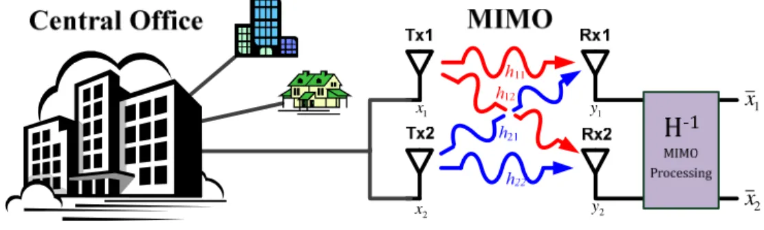
2 x 1 x 2 y 1 yFig. 1. Radio over fiber system with MIMO technology.
2. 2 × 2 MIMO technology with frequency domain equalization
Figure 1 shows the fundamental concept of a RoF system supporting 2 × 2 MIMO technology. After sending two different radio signals over fiber from a central office to two transmitter antennas behind photo detectors, Tx1 and Tx2 are used to radiate the wireless signals over the air. The signals are then received by two receiver antennas, Rx1 and Rx2. The received signals are the summation of the two transmitted signals with different channel coefficients due to the different propagation paths. Hence, the signals, y1 and y2 , received by Rx1 and Rx2,
1 11 12 1 1 2 21 22 2 2 y h h x w y h h x w = + (1) where x
1 and x2 represents the radio signals transmitted from Tx1 and Tx2, respectively, w1 and w2 represent the additive noises, and h
ij denotes the channel coefficient from Txi to Rxj,
as shown in Fig. 1. If the channel coefficient is measured by appropriate training symbols, the zero-forcing algorithm can be applied to estimate the transmitted signals [12]:
1 11 12 1 2 21 22 2 1 x h h y x h h y − = (2)
Moreover, since mm-wave electric and optical components have uneven frequency responses, the 60 GHz RoF system has a frequency response of more than 10 dB [5], which causes serious inter-symbol interference (ISI). Furthermore, fiber chromatic dispersion gives additional ISI after fiber transmission. However, dealing with the ISI impairments in the time domain significantly increases the complexity of MIMO signal processing. An alternative approach is to use FDE algorithms to compensate for ISI effects in the frequency domain, which greatly reduces the MIMO DSP complexity [10]. In this approach, the channel responses of the frequency components are measured to estimate the transmitted signals from the received ones in the frequency domain. In practice, because the discrete frequency components are obtained via discrete Fourier transform from a data block composed of finite symbols, a cyclic prefix (CP) with suitable length is required to avoid the interference between data blocks. Consequently, while a data block contains M symbols, the received frequency components of each block can be written as,
1, 11, 12 , 1, 1 2 , 21, 22 , 2 , 2 , 1, 2, l l l l l l l l Y H H X W l M Y H H X W = + = … (3)
where Xj,l, Yi,l, and Wi,j represents the l-th discrete frequency components of the transmitted signal from Txi, the received signal from Rxi, and the additive noise of the corresponding data block, respectively. The parameter Hij,l describes the channel response from Xj,l to Yi,l. Once Hij,l can be measured by appropriate training symbols, the discrete frequency components of the transmitted signals can be estimated by,
11, 12 , 1, 1, 21, 22 , 2 , 2 , 1 l l l l l l l l H H Y X H H Y X − = (4)
After applying the inverse discrete Fourier transform to , the transmitted signals evaluated by the FDE are obtained in the time domain.
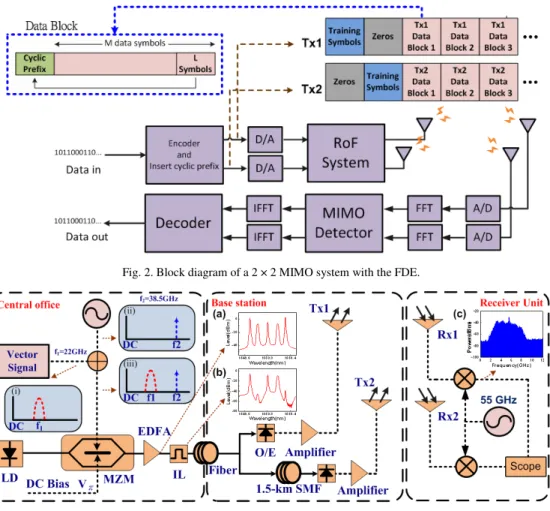
The block diagram of Fig. 2 illustrates the implementation of the 2 × 2 MIMO DSP algorithms incorporating FDE equalization. After the encoder, the binary data streams are divided into two independent data streams (representing the two MIMO data streams) and are mapped to the quadrature-amplitude modulation (QAM) format, which provides a high spectral efficiency. In order to uniquely identify the training symbols at the receiver, the training symbols have to be orthogonal [13]. In this work, the on-off training sequence is used to measure the channel coefficients. Each data block for the FDE consists of M + L symbols including M data symbols and L repeated symbols, which form the CP. The data streams are transmitted through fiber and air links before being received by two antennas at the receiver. Then, the MIMO processing is employed to decode the received signals, including fast Fourier transform (FFT), FDE, zero-forcing algorithm, inverse FFT (IFFT), and symbol decoder.
Fig. 2. Block diagram of a 2 × 2 MIMO system with the FDE.
Fig. 3. Experimental setup of the proposed system.
3. Experimental setup and results
Figure 3 schematically depicts the experimental setup of the proposed 60 GHz RoF system using the 2 × 2 MIMO scheme. The optical transmitter simply uses only one single-electrode Mach-Zehnder modulator (MZM) [5]. To realize directly-detected optical vector signals at 60.5 GHz, the driving RF signal consists of the vector signal at 22 GHz and the LO signal at 38.5 GHz. The MZM was biased at the null point to suppress the undesired optical carrier. Hence, the modulated optical signal consists of two data-modulated sidebands and two pilot tones as shown in inset (a) of Fig. 3. After MZM, an erbium doped fiber amplifier (EDFA) with 20 dB gain was utilized to compensate the loss. To prevent fiber chromatic dispersion induced fading, a 33/66 GHz optical interleaver is utilized to remove one data-modulated sideband and one pilot tone. The 16 QAM vector signal was generated at baseband by a Tektronix® AWG7102 arbitrary waveform generator (AWG) with 10 GHz sampling rate and the D/A resolution of 8 bits. The symbol rate of the signal was 3.5 GBaud. The vector signal was up-converted to 22 GHz using an I/Q mixer, while one data block comprises the data of M symbols and the CP of L symbols, the data rate of the 16-QAM signal that occupied the total bandwidth of 7 GHz is 14 ×
M/(M + L) Gb/s. At the base station, the optical vector signal was detected by a 67-GHz photodiode to generate the electrical 16-QAM signal at 60.5-GHz from optical field. Moreover, to emulate the second independent wireless signal required in our 2 × 2 MIMO system, the modulated optical signal was split into two parts with the second signal transmitted a further 1.5-km over fiber to generate a second uncorrelated 16-QAM signal at 60.5 GHz. In practice,
two independent RoF signals could be simultaneously transmitted over the same fiber by the polarization-division-multiplexing (PDM) or wavelength-division-multiplexing (WDM) schemes. After detection, two rectangular waveguide-based standard gain horn antennas with about 23 dBi gain were used to transmitt the 60 GHz signals over 3-m wireless distance. The combined data rate of the 60 GHz signals was 2 × [14 × M/(M + L)] = 27.15Gb/s. At the receiver, a second pair of identical antennas were used to receive the two mixed signals at 60.5 GHz, which were subsequently down-converted to 5.5 GHz as shown in inset (c) of Fig. 3. The down-converted signal was captured by a real time scope with a 50 GHz sampling rate and a 3-dB bandwidth of 12.5 GHz. An off-line DSP program was employed to demodulate the MIMO signals, including synchronization, FFT, FDE, zero-forcing algorithm, IFFT, and QAM symbol decoding. The bit error rate (BER) performance is calculated from the measured error vector magnitude (EVM). This experiment was conducted in the indoor (typical laboratory) environment.
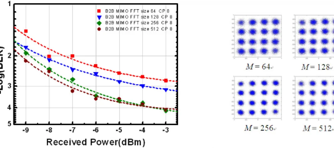
Figure 4 shows the BER curves of the MIMO signal generated before transmission over optical fiber. To investigate the impact of the FFT size of the FDE on the performance of the system, the CP was fixed to 8 symbols and the FFT size M varied from 64 to 512 symbols per data block. More symbols in one data block represent a higher resolution in the frequency domain, which should result in improved system performance with respect to ISI. This phenomenon is confirmed by the results shown in Fig. 4. Furthermore, Fig. 4 shows that the optimal FFT size for the measured RoF MIMO system was 256 symbols. The use of a higher FFT size does not result in system obvious performance improvement as shown in Fig. 4. This means that the FFT size of 256 is sufficient to prevent ISI in the tested system. Therefore, the FFT size of 256 was adopted in further system experiments. Figure 5 shows the impact of the CP size on the performance of the system. The result shows that there is no system improvement for CP sizes of greater than 8 symbols. This means that a CP equal to 1/32 was sufficient to prevent interference between blocks (IBI).
Fig. 4. BER curves of MIMO signals with different FFT sizes.
Based on experimental results as shown in Figs. 4 and 5, 2x2 MIMO signal transmission experiments were conducted using the FFT size of 256 symbols and a CP equal to 8 symbols. Results from the MIMO transmission experiments at the combined wireless data rate of 27.15 Gb/s are given in Fig. 6. It was observed that there was no performance penalty following transmission over 25 km standard single-mode fiber and 3 m wireless distance. The BER was well below the FEC limit in both cases. The 16-QAM constellation diagrams for the individual MIMO streams (Tx1, Tx2) and the combined MIMO signal (Tx1 + Tx2) given in Fig. 6 also confirm the excellent signal distribution and recovery.
Fig. 5. BER curves of MIMO signals with different CP lengths.
Fig. 6. BER curves of 27.15Gbps MIMO signals.
4. Conclusions
This work experimentally demonstrates the efficacy of the 2 × 2 MIMO technique in a 60-GHz RoF system. The wireless data capacity of a single-carrier 60 GHz Radio-over-Fiber system was successfully double from 13.6 Gb/s to 27.15 Gb/s using the MIMO technique. FDE equalization was used to compensate for frequency response originating from the uneven RoF link response. Transmission over both 25 km standard single-mode fiber and 3 m wireless distance were achieved with negligible penalty. The optimum FDE parameter requirements in terms of the FFT and the CP were investigated and found to be moderate.