國 立 交 通 大 學
電機資訊學院 電子與光電學程
碩 士 論 文
多種互補式金氧半場效電晶體製造相容之感測層材料在酸
鹼離子感測器之研究
The study of various CMOS manufacturing
compatible sensing layers on pH-ISFET
研 究 生: 張知天
Student: Chih-Tien Chang
指導教授: 張國明 博士
Advisor: Dr. Kow-Ming Chang
多種互補式金氧半場效電晶體製造相容之感測層材料在酸
鹼離子感測器之研究
The study of various CMOS manufacturing comparable
sensing layers on pH-ISFET
研 究 生: 張知天
Student: Chih-Tien Chang
指導教授: 張國明 博士
Advisor: Dr. Kow-Ming Chang
國立交通大學
電機資訊學院 電子與光電學程
碩士論文
A Thesis
Submitted to Degree Program of Electrical Engineering Computer
Science College of Electrical Engineering and Computer Science
National Chiao Tung University
in Partial Fulfillment of the Requirements
for the Degree of
Master of Science
in
Electronics and Electro-Optical Engineering
June 2005
Hsinchu, Taiwan, Republic of China
中華民國九十四年六月
多種互補式金氧半場效電晶體製造相容之感測層材料在酸
鹼離子感測器之研究
學生:張知天 指導教授:張國明 博士
國立交通大學
電機資訊學院 電子與光電學程碩士班
摘要
本論文係利用互補式金氧半導體(Complementary Metal Oxide Silicon Field Effect Transistor, CMOS) 標準製程完成酸鹼值離子感測場效電晶體(pH-Ion Selective Field Effect Transistor, pH-ISFET)的製作。pH-ISFET與CMOS不同的是將 金屬閘以離子感應層(Ion Sensing Layer)、酸鹼緩衝溶液(pH Buffer Solution) 和一 外加之參考電極取代,元件的電性隨著離子感應層和溶液的表面接觸性質而改
變。本實驗安排多種與CMOS製程相容的材料,如氮化矽(Si3N4)、三氧化二鋁
(Al2O3)、二氧化鋯(ZrO2)、二氧化錫(TiO2)以及二氧化鉿(HfO2)等配合不同的通
道長寬比以及製程條件來製作離子感應層,利用不同材質的感應層,其化學平衡 的機制不同對飄移速率、感應度、反應時間、穩定度等元件特性的影響來尋求最 佳特性材料。 在此篇論文中,我們將詳述酸鹼離子感測器的製作流程及量測條件,並且在 文末藉由實驗數據來分析各種離子感應層的特性;此外,敘述利用NH3電漿對各 種離子感應層作表面處理對pH-ISFET特性的影響及改善。
The study of various CMOS manufacturing compatible
sensing layers on pH-ISFET
Student: Chih-Tien Chang Advisor: Dr. Kow-Ming Chang
Degree Program of Electrical Engineering Computer Science College of Electrical Engineering and Computer Science
National Chiao Tung University
Abstract
In this thesis, standard manufacture processes of Complementary Metal Oxide Semiconductor (CMOS) are introduced to fabricate Ion-selective Field Effect Transistors (ISFET). This device is differ from MOSFET on the metal gate of MOSFET was substituted by an ion-sensing layer, pH buffer solution and an additional reference gate. The I-V characteristic curves were altered by the interface reactions of sensing layer and electrolyte solution. In our experiment, we use various
CMOS fabrication compatible materials, such as silicon nitride (Si3N4), aluminum
oxide (Al2O3), zirconium dioxide (ZrO2), Tinoxide (TiO2) and hafnium dioxide
(HfO2), with several width/length channel dimension and different process techniques
to produce ISFETs. The materials will cause different characteristics such as drift, sensitivity, response time and stability.
In this thesis, we reported the fabrication process flow and measurement condition in detail, and analyzed the characteristics mentioned above.
誌謝
首先,我要感謝張國明教授在碩士班這兩年給予我的指導與教誨,使我無論 在半導體元件以及相關知識的長進,做學問的態度或是待人處事及論文寫作等方 面都獲得莫大的助益。 其次,感謝奈米中心及國家奈米實驗室全體人員在實驗過程中的幫忙及協 助,使我可以順利進行我的實驗。並且特別感謝口試委員桂正楣教授以及龔正教 授的蒞臨指導,讓我在口試過程中對於我的研究有新的體認,相信對於以後的研 究有莫大的幫助 再者,感謝趙高毅學長,在實驗過程中不斷的給予協助、鼓勵及建議,並且 提供我許多寶貴的經驗,讓我在學習的過程更加順利。還有實驗室的同學黃俊皓 和吳冠增,感謝你們的協助讓我在工作百忙之餘仍能順利完成在奈米中心及國家 奈米實驗室的各樣考核並且順利完成論文實驗。 此外,還要感謝我在台積電研發部門的上司周梅生博士以及陳炳宏博士,他 們鼓勵並推薦我到交大研究所進修並且給予我最大的空間,讓我得以順利完成繁 重的課業並且取得良好的成績。 最後要感謝我的父母與太太,因為他們的支持與鼓勵,讓我在研究過程中無 後顧之憂,得以順利完成我的碩士論文及學位。 誌于 2005. 06 張知天Content
Abstract (in Chinese)……….…..i
Abstract (in English)………...ii
Acknowledgements (in Chinese)………..…..iii
Contents……….….iv
Figure caption………..………...vi
Table captions……….…..viii
Chapter 1 Introduction
1.1 Motivation of this work………11.2 Brief history of ISFET….……….………..…..1
1.3 Introduction to ISFET………..……….………2
1.4 Thesis organization………...4
1.5 References……….…4
Chapter 2 Theory Description
2.1 Definition of pH………...………...62.2 Principle of ISFET……….….…………...…...6
2.2.1 From MOSFET to ISFET………..6
2.2.2 Potentiometry……….…....8
2.2.3 Electrode and electrolyte interface……….…9
2.2.4 Theory for the pH sensitivity………..…..12
2.2.5 Reference electrode………...………..….14 2.3 Summary………...…15 2.4 References………...15
Chapter3 Experiment
3.1 Introduction……...………...…….…..17 3.2 Preparation of ISFET……….….173.3 ISFET fabrication process flow………..…….17
3.4 Key steps illustration………...……..……..19
3.2.1 Gate region formation……….…….19
3.2.2 Sensing layers deposition………..…….…..19
3.5.1 Considerations of chemical sensor measurements………...20
3.5.2 Preparation of measurement……….……22
3.5.3 Current-Voltage measurement set-up….……….….22
3.5.4 Hysteresis measurement set-up………...….…23
3.5.5 Drift measurement set-up………....….23
3.6 References ………...….23
Chapter 4 Results and discussions
4.1 Introduction……….……254.2 Characteristics of sensing materials………25
4.2.1 Sensitivity, drift and hysteresis characteristics of ZrO2 membrane ………...………….…...…26
4,2,2 Sensitivity, drift and hysteresis characteristics of HfO2 membrane ………..….26
4.2.3 Sensitivity and hysteresis characteristics of Al2O3 membrane ………..………..…...27
4.2.4 Sensitivity and hysteresis characteristics of TiO2 membrane ……….…………..……27
4.2.5 Sensitivity, drift and hysteresis characteristics of Si3N4 membrane ………27
4.3 Comparison of sensing layers………..…….28
4.3.1 The comparison of sensitivity and linearity characteristics….….28 4.3.2 The comparison of hysteresis characteristics………....28
4.4 Discussion of NH3 plasma surface treatment………….……….…….29
4.5 .Conclusions………..…………...….…..….30
Chapter 5 Future work
5-1 Future work………...……..……31Figure captions
Figure 1-1 Basic structure and operation of N-channel ISFET Figure 1-2 pH Response of N-channel ISFET
Figure 2-1 Operation principle of MOSFET
Figure 2-2 Metal gate of MOSFET replace by reference electrode and electrolyte
Figure 2-3 Electrode and electrolyte
Figure 2-4 (a) Helmholtz model (b) redistribution effects of Helmholtz model
Figure 2-5 Schematic representation of the side-binding model Figure 2-6 Potential profile and charge distribution at an oxide
electrolyte solution interface Figure 3-1 Fabrication process flow Figure 3-2 Measurement system and setup
Figure 4-1 Id-Vg characteristics of ZrO2 film on different pH values
Figure 4-2 pH sensitivity and linearity of ZrO2 film
Figure 4-3 Drift characteristic of ZrO2 film
Figure 4-4 Hysteresis phenomenon of ZrO2 film
Figure 4-5 Id-Vg characteristics of HfO2 film on different pH values
Figure 4-7 Drift characteristic of HfO2
Figure 4-8 Hysteresis phenomenon of HfO2 film
Figure 4-9 Id-Vg characteristics of Al2O3 film on different pH values
Figure 4-10 pH sensitivity and linearity of Al2O3 film
Figure 4-11 Hysteresis phenomenon of Al2O3 film
Figure 4-12 Id-Vg characteristics of TiO2 film on different pH values
Figure 4-13 pH sensitivity and linearity of TiO2 film
Figure 4-14 Hysteresis phenomenon of TiO2 film
Figure 4-15 Id-Vg characteristics of Si3N4 film on different pH values
Figure 4-16 pH sensitivity and linearity of Si3N4 film
Figure 4-17 Hysteresis phenomenon of Si3N4 film
Figure 4-18 Drift characteristic of Si3N4
Figure 4-19 Sensitivity and linearity characteristics of ZrO2 in acid/base
Figure 4-20 Sensitivity and linearity characteristics of sputtered HfO2 in acid/base
Figure 4-21 Sensitivity and linearity characteristics of E-gun HfO2 in acid/base
Figure 4-22 Sensitivity and linearity characteristics of Al2O3 in acid/base
Figure 4-23 Sensitivity and linearity characteristics of TiO2 in acid/base
Figure 4-24 Sensitivity and linearity characteristics of Si3N4 in acid/base
Figure 4-25 Hysteresis phenomenon of ZrO2 film after NH3 plasma treatment
treatment
Figure 4-27 Hysteresis phenomenon of E-gun HfO2 film after NH3 plasma
treatment
Figure 4-28 Hysteresis phenomenon of E-gun Al2O3 film after NH3 plasma
treatment
Figure 4-29 Hysteresis phenomenon of E-gun TiO2 film after NH3 plasma
treatment
Figure 4-30 Hysteresis phenomenon of Si3N4 film after NH3 plasma treatment
Figure 4-31 Acid/ Base sensitivity deviation characteristic of sensing films
Figure 4-32 Linearity comparison of sensing films with/ without NH3 plasma post
surface treatment
Figure 4-33 Hysteresis/ sensitivity comparison of sensing films with/ without NH3
plasma post surface treatment
Figure 4-34 Acid/ Base sensitivity deviation characteristic of sensing films
Table caption
Chapter 1
Introduction
1.1 Motivation of this work
The most often mentioned advantages of ISFET are small sample volume, multiple sensors on a single chip, fast response, mass producible and cheap cost possibility. CMOS based manufacturing techniques are the main stream in this industry. For integrating ISFET, REFET and pseudo-reference electrode on a chip, the sensing films which be deposited on gate oxide must be CMOS manufacturing compatible to achieve the cheap cost purpose. In
this work, we chosen Si3N4, TiO2, HfO2, ZrO2 and Al2O3 as sensing films and fabricated
the ISFET under identical or designed process conditions to study the sensing characteristics and figure out the feasibility of CMOS process fabrication.
Meanwhile, all of those films are oxide based which can be explained simultaneously with same side-binding theory, via the experimental result we can easily find proper explanations for sensitivity, hysteresis and drift characteristics of ISFETs.
1.2 Brief history of ISFET
Sensors applied on many areas contain a wide range of fields including electrical, magnetic, physical, optical, thermal, and chemical. The pH sensors belong to the category of ‘chemical sensors’. The concept of the chemical sensor was first introduced in 1962 by the late Professor Kiyoyama of Kyushu University. Work in the field of FET chemical sensors began ten years after the discovery of the gas sensor.
The first paper on the ISFET was that published by Bergveld in 1970 [1]. This paper describes the details of measurement of ion density with an ISFET-only configuration
without a reference electrode. In 1971, the late Professor Matsuo [2-3] conducted research on a high- impedance circuit using an organic microelectrode with a FET which proposed a measurement system employing the reference electrode.
In 1978, an ISFET on a silicon island isolated by a P-N junction and insulator was proposed [1]. The discovery of the planar ISFET has been a revolutionary development for researchers previously restricted by the need for an insulating coating on the silicon substrate.
1.3 Introduction to ISFET
Compare with conventional pH-meter using glass electrode, ISFET possessed of following advantages: (1) micro-miniaturization: only need little media exposed, (2) excellent electrical characteristics: high input impedance and low output impedance result in high S/N ratio, (3) widen applications: such as bio-sensor or other micro-sensors, (4) MOSFET process compatible: easy to achieve mass production and low cost [4-7]. However, a variety of questions needed to be answered before chemical sensors were able to operate stably in a solution, the primary questions being (1) whether the FET device was able to operate as a chemical sensor, (2) whether it could be mass-produced, (3) whether it could be operated reliably in solutions for long periods, and (4) whether it would be competitive with the conventional pH meter using glass electrodes.
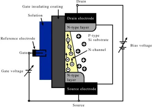
The ISFET pH sensor is a semiconductor device received little media exposure. An explanation of its basic principles of operation is therefore given below. Fig. 1-1 shows a typical N-channel ISFET structure. The gate electrode consists of an electrolytic solution adhering to a thin insulating coating deposited on a P-type silicon substrate. The insulating
coating is ion sensitive, and the term ‘Ion Sensitive Field Effect Transistor (ISFET)’, is derived from this gate structure.
Operation of the device employs the charge channel formed under the insulating coating. The source electrode and drain electrode are also created at the both side of gate, and application of a voltage between the two results in an N-type conduction current. This is the so-called N-channel FET.
The carrier path along which the carrier accumulated under the insulation coating flows from right to left in the diagram (parallel to the oxide coating) is controlled by the gate potential applied to the insulating coating, and thus forms a potential-response type pf sensor able to control the current between the drain and source. When the concentration of hydrogen ions in the solution increases the positive hole forming the primary carrier of the P-type semiconductor reacts and retreats from the area immediately below the gate insulation coating, while the few electrons remaining in the P-type layer are attracted to the area immediately below the gate. As the hydrogen ion concentration increases the N-channel layer increases in thickness, allowing a greater current flow, and thus permitting detection of ion concentration, as shown in Fig.1-2.
The sensing properties of the pH-ISFETs were mainly dependent on various materials owing to the different reactivity of the electrolyte with materials. In the past, for detecting
pH, many sensitive materials, such as, SiO2 [1], Si3N4 [8], Al2O3 [9], Ta2O5 [10], WO3 [11],
SnO2 [12,13], etc. have been investigated. However, it is reported that these material have
lower pH-sensitivity than Nernst values. The first membrane used was SiO2 and
unsatisfactory sensitivity and dynamic response was obtained. Subsequently, Si3N4, Al2O3,
Ta2O5, WO3 and SnO2 and were used as pH-sensitive dielectrics because of the higher pH
response. Moreover, pH-ISFETs based on electron conducting material are widely investigated now because of low drift and hysteresis. [14]
1.4 Thesis organization
In this thesis, varies of MOSFET fabrication compatible materials, Si3N4, Al2O3, HfO2,
TiO2 and ZrO2, were produced as pH sensing layers. At the first section, brief history and
characterizations of pH-ISFET were addressed. Following illustrated the operation theories, which including pH definition, how from MOSFET to ISFET, the Nernst equation of providing a quantitative relationship between the observed potential and concentration of the species in the electrochemical cell and the theories of electrode and electrolyte interface. All of them dominate the development of pH-ISFET. In chapter 3, considerations of chemical sensor measurements, the procedures of fabrication and measurement of varies sensing layers with standard MOS manufacture processes were described. At last, the investigated characterizations, comparison result and future works were reported in chapter 4 and 5.
1.5 References
[1] P. Bergveld, “Development of an ion sensitive solid-state device for neurophysiological measurements”, IEEE Trans.Biomed. Eng.,vol. BME-17, p.70, 1970.
[2] T. Matsuo and K.D. Wise, An integrated field-effect electrode for biopotential recording, IEEE Transactions on Bio-Medical Engineering 21 (1974) 485.
[3] T. Matsuo and M.Esashi, Method of ISFET fabrication, Sensors and Actuators 1 (1982) 77.
[4] A. Merlos, E. Cabruja, New technology for easy and fully IC-compatible fabrication of backside-contacted ISFETs, Sensors and Actuators B 24-25 (1995)228.
[5] J. Bausells, J. Carrabina, A. Errachid and A. Merlos, Ion-sensitive field-effect transistors fabricated in a commercial CMOS technology, Sensors and Actuators B 57 (1999) 56.
[6] A. Merlos, E. Cabruja, J. Esteve, “New technology for easy and fully IC-compatible fabrication of backside-contacted ISFETs”, Sensors and Actuators B 24-25, pp.228-231, 1995.
[7] Erik Lauwers, “A CMOS Multiparameter Biochemical Microsensor With Temperature Control and Signal Interfacing”, IEEE Journal of solid state circuit, vol 36, No. 12 December 2001.
[8] George T. Yu, “Hydrogen ion diffusion coefficient of silicon nitride thin films”, Applied Surface Science 202, pp.68-72, 2002.
[9] Jung-Chuan Chou,” Sensitivity and hysteresis effect in Al2O3 gate pH-ISFET”, Material Chemistry and Physics 71, pp120-124, 2001.
[10] Yoshitaka, “Long-term drift mechanism of Ta2O5 gate pH-ISFETs”, Sensors and Actuators B 64, pp.152-155, 2000.
[11] Jung-Chuan Chou, “Ion sensitive field effect transistor with amorphous tungsten trioxide gate for pH sensing”, Sensors and Actuators B 62, pp.81-87, 2000.
[12] Li-Lun Chi, “Study on extended gate field effect transistor with tin oxide sensing membrane”, Material Chemistry and Physics 63, pp19-23, 2000.
[13] Hung-Kwei Liao, “Study of amorphous tin oxide thin films for ISFET applications”, Sensors and Actuators B 50, pp.104-109, 1998.
[14] Jung Chuan Chou, “Preparation and study on the drift and hysteresis properties of the tin oxide gate ISFET by the sol–gel method”, Sensors and Actuators B 86, pp.58-62,2002.
Chapter 2
Theory Description
2.1 Definition of pH
In its most common interpretation, pH is used to specify the degree of acidity or basicity of an aqueous solution. In formal, the definition of pH is expressed as
log H log [ ]
pH a + γ H
+
= − = − (2-1)
where aH+ is the hydrogen ion activity, γ is the activity coefficient which equals to 1
when diluted solution, and is the molar concentration of solvated protons in units of
moles per liter.
[H+]
In practice, the measurement of pH is not accomplished by the direct determination of the hydrogen ion activity but relative to standard solution of known pH. The result pH depends on a number of factors, such as the concentration of the added acid and its dissociation constant [1].
2.2 Principle of ISFET
Electrochemical measurement of pH utilizes devices that transduce the chemical activity of the hydrogen ion into an electronic signal, such as an electrical potential difference or a change in electrical conductance.
The ISFET is a new approach of electrochemical measurement of pH, which developed on the basis of the MOSFET, it is nothing else than a MOSFET with the gate connection separated in the form of a reference gate immersed in aqueous solution which is contact with the sensing layer above gate oxide. The basic principle of MOSFET as follows: 1. Control of current flowing between two electrodes drain and source. 2. The gate electrode can only influence the drain-source current electrostatically. 3. The MOSFET’s gate consists of a metallic coating and is used as an electrode to control the drain-source
current through external potential V . The operation principle is illustrated in Fig. 2-1. gs
The general expression for the drain current of the MOSFET and thus also of the ISFET in the non-saturated mode is
(
)
1 2 2 d ox gs t ds ds W I C V V V V L µ ⎡ ⎤ = ⎢ − − ⎥ ⎣ ⎦ (2-2)with Cox is the oxide capacity per unit area, W and L the width and the length of the
channel, respectively, and μ is the electron mobility in the channel.
The second important MOSFET equation describes the physical properties in nature is that of the threshold voltage
2 M Si ox ss B t ox Q Q Q V q C φf Φ − Φ + + = − + (2-3)
Where the first term describes the work function difference between the gate metal (Φ ) M
and the silicon ( ), the second term is describes the effect of accumulated charge in the
oxide ( ), at the oxide-silicon interface (
Si Φ ox
Q Q ) and the depletion charge in the silicon bulk ss
( ), the last term determines the onset of inversion depending on the doping level of the
silicon. B
Q
In the case of ISFET, the metallic gate is replaced by a special oxide-coated gate which is sensitive to hydrogen ion activity is shown in Fig. 2-2. When immersed in a liquid, the electrical circuit is connected with the reference electrode and the hydrogen activity can
influence the drain-source current, due to the drain current Id is an unique function of the
input voltage Vgs , meanwhile, the applied drain-source voltage Vds and the threshold
voltage Vt are constant, the geometric sensitivity parameter β µ= C W Lox / . The β is a
design constant and Vds is kept constant by the applied electronic circuit. Defining the metal
connection of the reference electrode suggests that the observed ion sensitivity was described as an additional input variable of any interfacial potential in the input circuit
should be described in terms of Vt.
Hence the expression for the ISFET threshold voltage becomes
0 2 sol Si ox ss B t ref ox Q Q Q V E q C f χ Φ + + φ = − Ψ + − − + (2-4)
where Eref is the constant potential of the reference electrode, Ψ is the chemical input 0
parameter and χsolis the surface dipole potential of the solvent and thus having a constant
value [2]. All terms are constant except Ψ , so it is the term dominates the sensitivity of 0
ISFET to the electrolyte pH, which is controlling the dissociation of the oxide surface. Therefore, detailed investigation of the electrode-electrolyte interface is necessary for designing a high pH sensitivity ISFET.
2.2.2 Potentiometry
Before discussing electrode-electrolyte, let’s review potentiometry first. Potentiometry is the study of electrochemical cells at equilibrium, i.e. measurement of potential at zero current. For the general reaction
xO ne+ −U yR (2-5) where O and R are the oxidized and reduced forms of the analyte species and n is the number of electrons, e, transferred in the reaction. If the LHE is the standard hydrogen half cell, the overall reaction may be represented:
2
( / 2)n H +xOU yR nH+ + (2-6)
The cell free energy for the energy is given by
[ ]
[ ] [ ]
0 / 2 2 ln n y x n R H G G RT O H + ⎧ ⎡ ⎤ ⎫ ⎪ ⎣ ⎦ ∆ = ∆ + ⎨ ⎪ ⎪ ⎩ ⎭ ⎪ ⎬ 1 (2-7)where R is the gas constant, T is the absolute temperature and is the standard free
energy of the system at 298K and 1 atm.
0 G ∆ Since nFE G=− ∆ (2-8)
where F is Faraday constant and by definition [H+] [= H2]= for the standard hydrogen
electrode. The Nernst equation
[ ]
[ ]
0 ln x y O RT E E nF R ⎧ ⎫ ⎪ = + ⎨ ⎪ ⎪ ⎩ ⎭ ⎪ ⎬ (2-9)which provides a quantitative relationship between the observed potential and concentration of the species in the electrochemical cell.
2.2.3 Electrode and electrolyte interface
Electrolyte is a substance with ionic dc conductivity, pure electrolytes whose charge carriers are and no separate flow of electron. For electrode, two current carrying electrodes in an electrolyte are the source and sink of electrons, the electrode is the site of a charge carrier shift, a charge exchange between electrons and ions. There are three types of electrode: (1) Ohmic contact, (2) capacitive type and (3) covered with a permeable membrane.
In regard to the electrode and electrolyte interface, shown in Fig. 2-3, which has the following properties: (1) local concentration of both cation and anion changes at the
interface, (2) ion-electron exchange, i.e., redox reaction, (3) ion-electron interaction, no redox reaction, and (4) ion-molecular interaction, insulator for example. The selectivity and chemical sensitivity of the ISFET are completely controlled by the properties of the interface, protonation/ deprotonation of the gate material is influenced by the pH at the gate area, which controls the surface potential.
The model which gave rise to the term ‘electrical double layer’ was first put forward in the 1850’s by Helmholtz. Many double layer theories were proposed and now brief describe as follows:
Helmholtz double layer: A simplistic description of the electric double layer as a condenser (the Helmholtz condenser) in which the condenser plate separation distance is the Debye length. The Helmholtz layer is divided into an inner Helmholtz plane (IHP) of adsorbed, dehydrated ions immediately next to a surface and an outer Helmholtz plane (OHP) at the center of a next layer of hydrated, adsorbed ions just inside the imaginary boundary where the diffuse double layer begins, That is, both Helmholtz planes are within
the Stern layer. Helmholtz’s view of the region is shown in the Fig. 2-4
Gouy-Chapman double layer: In case of Gouy-Chapman theory, it is assumed that the diffuse layer of ions begins at some distance away from the surface, and the complete Poisson-Boltzman equation is used.
Stern Grahame theory: The layer of ions in an electric double layer that, hydrated or not, lie adjacent to the surface (adsorbed ions). The rest of the electric double layer is often distinguished as the diffuse part, where assumptions, such as treating the ions as point charges, can more reasonably be made. (Gouy-Champman diffuse layer)
Gouy-Chapman double layer model combined with Stern Grahame theory is the most general.
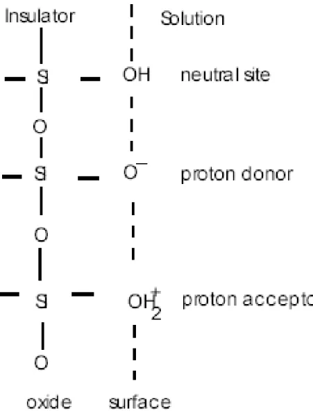
The site-binding model, illustrated in Fig. 2-5, is indicated that reactions can happen
between protons ( in the solution and the hydroxyl groups formed at the
oxide-solution interface. The model which introduced by Yates et al. [3] are used to derive the intrinsic buffer capacity for several oxides and silicon nitride.
)
H+
This model describes equilibrium between the so-called amphoteric SiOH surface
sites and the H+-ions in the solution. The reactions are
B AOH U AO−+H+ + (2-10) and 2 B AOH+ U AOH H+ (2-11)
where HB+ represents the protons in the bulk of the solution. An originally neutral surface
hydroxyl site can bind a proton from the bulk solution, becoming a positive site and leaving a negative site on the oxide surface. It is called amphoteric site.
It is known that the background electrolyte has a large influence on the surface charge [4]. This dependence is ascribed to variations in the double layer capacitance. The Gouy-Chapman-Stern model is most widely used to describe the double layer structure in ISFET literature [5].
Gouy and Chapman proposed independently the idea of a diffuse layer to interpret the capacitive behavior of an electrode/electrolyte solution interface. The excess charge in the solution side of the interface is equal in value to that on the solid state surface, but is of opposite sign. The ions in the solution are therefore electrostatically attracted to the solid-state surface but the attraction is counteracted by the random thermal motion which acts to equalize the concentration throughout the solution. However, this theory has one major drawback. The ions are considered as point charges that can approach the surface
arbitrarily close. This assumption causes unrealistic high concentrations of ions near the
surface at high values of Ψ0.
An adjustment to solve this problem was first suggested by Stern. He proposed a
diffuse layer of charge in the solution starting at a distance X from the surface. After that,
a complete model is defined.
2.2.4 Theory for the pH sensitivity of ISFET
A new model was introduced by van Hal and Eijkel [6,7 ] and is in fact nothing else
than the well-known equation for capacitors Q CV= , where is surface charge in the
form of protonized or deprotonized
Q
(
OH2+
)
( )
O− OH groups of the oxide surface, isthe double-layer capacitance at the interface and V is the resulting surface potential,
denoted as Ψ
C
0 in Eq. 2-4. This potential between the gate insulator surface and the
electrolyte solution causes a proton concentration difference between bulk and surface that is according to Boltzmann: 0 exp s B H H q a a KT + + − = Ψ (2-10) or 0 2.3 S B q pH pH KT = + Ψ (2-11) where i H
a + is the activity of H+; q is the elementary charge, is the Boltzmann
constant and is the absolute temperature. The subscripts
K
T B and refer to the bulk
and the surface, respectively.
S
Here define two parameters: βS and CS. βS symbolizes the surface buffer capacity,
e.g. the ability of the oxide surface to deliver or take up protons, and CS is the differential
of the bulk solution via the corresponding Debije length. Now we get 0 S s q pH σ β ∆ = − ∆ (2-12)
where σ0 is the surface charge per unit area. The buffer capacity,βS, is called the intrinsic
buffer capacity because it is the capability to buffer small changes in the surface pH
(pHs),but not in the bulk pH (pHB).
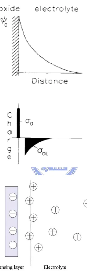
Because of charge neutrality, an equal but opposite charge is built up in the electrolyte
solution side of the double layerσDL , shown in Fig. 2-6. This charge can be described as a
function of the integral double layer capacitance, Ci, and the electrostatic potential
σDL=-CiΨ0=-σ0 (2-13)
The integral capacitance will be used later to calculate the total response of the ISFET on changes in pH. The ability of the electrolyte solution to adjust the amount the of stored charge as result of a small change in the electrostatic potential is the differential
capacitance, CS 0 0 0 DL S C σ σ ∆ ∆ = − = − ∆Ψ ∆Ψ (2-14)
As a result, combine all Eqs. as
0 s pH ∆Ψ ∆ = σ00 ∆ ∆ Ψ 0 s pH σ ∆ ∆ = C S S qβ − = 0 0 ( ) 2.3 B q pH KT ∆Ψ Ψ ∆ + (2-15)
Rearrange Eq. 2-15 gives a general expression for the sensitivity of the electrostatic potential to changes in the bulk pH
0 2.3 B kT pH q α ∆Ψ = − ∆ (2-16) with 2 1 2.3 1 S S kTC q α β = + (2-17)
Note thatαis a dimensionless sensitivity parameter and the value ofαvaries between 0 and 1 depending on the intrinsic buffer capacity and the differential capacitance. Only in case α approach 1, the maximum Nernstian sensitivity of 58.2 mV/pH at 298K can be obtained.
Eq. 2-17 shows that α =1 is reached for oxides with a large value of the surface buffer
capacity βS and a low value of the double layer capacity CS. It shows that the SiO2 film
from the MOSFET process does not fulfill the requirements of a high value of βS. The pH
sensitivity is low depending also on the electrolyte concentration through . Therefore
other films such as Si
S
C
3N4, Al2O3 and ZrO2 were introduced to increase the values of βS.
The higher the intrinsic buffer capacity, the less important of the value of which
means that independent of the electrolyte concentration a Nernstian sensitivity can be achieved over a pH range from 1 to 13.
S
C
2.2.5 Reference electrode
ISFETs are typically biased using a Ag/AgCl reference electrode. Ideal reference electrodes are required to have the following characteristics: (1) Stable and reproducible potential (2) low temperature dependence of potential (3) low electrical resistance (4) application in variety of media (5) reproducible and small liquid junction potentials. A more common reference electrode is the silver/silver chloride electrode. The electrode reaction is effectively:
( ) ( )
AgCl s +e− →Ag s +cl− (2-18)
and the electrical response is ) ( ln ) / ( 0 − − =E RT F a Cl E (2-19)
For the difficulty of implementing reference electrode on-chip, and alternative technique is to make differential measurements between an ISFET and a pH-insensitive reference FET (REFET). However, we are not focus on this topic today.
2.3 Summary
Summarizing this chapter on the theoretical explanation of the pH sensitivity of ISFET, it should be concluded that an ISFET is an electronic component, similar to the MOSFET, but with an modulation possibility of the threshold voltage by means of the oxide/solution interface potential. The relation between this interface potential and the pH is determined by the buffer capacity of the oxide surface. Note that due to the introduction of the field effect concept in the sensor field, now also insulating materials can be used for ion sensing, contrary to the conducting materials that required for the conventional ion sensor concept, such as the glass membrane. The only prerequisite for these insulating materials is that their surface buffers the ion of interest.
2.4 References
[1] D.A. Skoog, D.M. West, and F.J. Holler, Fundamentals of Analytical Chemistry, 7th ed.,
Philadelphia, PA: Saunders College Publishing, 1996.
[2] P. Bergveld, Thirty years of ISFETOLOGY What happened in the past 30 years and what may happen in the next 30 years, Sensors and Actuators B 88 (2003) 1-20
[3] W.M. Siu and R.S.C. Cobbold, Basic properties of the electrolyte-SiO2-Si system: Physical and theoretical aspects. IEEE Trans. Electron devices ED-26 pp.1805-1815, 1979.
[4] T. Hiemstra, W.H. van Riemsdijk and G.H. Bolt, Multisite proton adsorption modeling at the solid/solution interface of (hydr) oxides: A new approach, J.Colloid Interface Sci., 133 pp.91-104, 1989.
[5] J.C. Van Kerkhof, ISFET responses on a stepwise change in electrolyte concentration at constant pH, Sensors Actuators B 18, pp56-59, 1994.
[6] R.E.G. van Hal, J.C.T. Eijkel, P. Bergveld, A novel description of ISFET sensitivity with the buffer capacity and double layer capacitance as key parameters, Sens. Actuators B 24/25 (1995) 201-205
[7] R.E.G. van Hal, J.C.T. Eijkel, P. Bergveld, A general model to describe the electrostatic potential at electrolyte oxide interfaces, Advances in Colloid and Interface Science 69, pp. 31-62, 1996.
Chapter 3
Experiment
3.1 Introduction
Since P. Bergveld [1] first employed the field-effect transistor for neuropsychological measurements in 1970, ISFET’s have developed into a new type of chemical sensing electrode. The device is similar to the conventional MOSFET except that the metal gate electrode is removed in order to expose the underlying insulator layer to the solution. Many theoretical and experimental studies have been published describing the behavior of this chemical sensing electronic device [2]. Applying the successful integration-circuit technology, the ISFET devices have potential advantages over conventional ion selective glass electrodes in their rapid response, low cost, small size, high input impedance and low output impedance [3].
3.2 Preparation of ISFET
To investigate the properties of Al2O3, TiO2, Si3N4, HfO2 and ZrO2 as the pH-sensing
layers, the ISFET were fabricated. All processes were accomplished in NDL (National Nano Device Laboratory) and Nano Facility center.
3.3 ISFET Fabrication Process flow
layers of TiO2, Si3N4, HfO2, Al2O3 and ZrO2 membranes are deposited onto the SiO2 gate
ISFET, which prepared by various standard MOSFET fabrication techniques. The nitride was deposited by LPCVD, tin oxide, hafnium dioxide, aluminum oxide and zirconium dioxide were deposited by e-gun and sputter, respectively, to form a double-layer gate. The fabrication parameters are listed in Table 3-1, and the fabrication procedures are listed as follows:
1. RCA clean
2. Wet oxide growth (600 nm.), 1050℃, 65min 3. First photo mask to define S/D
4. BOE wet etch oxide
5. Dry (Screening ) oxide growth (300 Α ), 1050℃, 12min ο
6 .Source/Drain implantation
※ Dose=5E15 (1/cm2), Energy=25Kev (n-type)
7. N+ anneal , 950℃ 30min
8. PE- oxide deposition (1μm)
9. Second photo mask to define contact hole & gate region 10. BOE etch PE- oxide 1μm (contact hole region)
PE- oxide 1μm+ wet oxide 6000Α (gate region) ο
11. Dry oxide grow (100 Α ), 850℃, 60min ο
12. Sensing layer deposition
※ Deposit low stress nitride by LPCVD
※ Deposit Tin oxide, aluminum oxide, hafnium dioxide and zirconium dioxide by sputter and e-gun, respectively
14. Sensing layer etching
15. Fourth photo mask to define Ti/Pt region 16. Deposit Ti/Pt
17. Pt annealing
18. Thermal coater Al (back side) 5000Α ο
3.4 Key steps illustration
3.4.1 Gate region formation
RCA clean is usually performed at wafer starting to reduce the possible pollution such as particles, organics, diffusion ions and native oxide. Careful RCA clean will ensure the integrity of device electricity. The next step 600nm thickness wet oxide is deposited as
barrier layer for S/D implant. The density and the energy of S/D implant is 5E15 (1/cm2)
and 25Kev with phosphorous dopant, respectively. In our experiment, p-type wafer is used .
After S/D implanting, following a 950℃ 30min N+ anneal performed to activate the
dopants.
Extra 1μm thickness PE oxide deposition is essential, which protect the structure of a pH-ISFET [4]. During a long period of electrolyte immersing, ions may diffuse and affect the ISFET’s electrical characterization [5]. It is a significant difference compare with standard MOSFET processes. A thick PE- oxide deposition can eliminate the effect.
Following the PE- oxide deposition, 100Α thickness dry oxide was grown in oven as gate ο
oxide.
This procedure is the most important part in our experiment. Various sensing material with different deposition techniques decides the characteristics of drift, hysteresis and sensitivity. For comparing these sensing layers, several deposition techniques were performed. We adopted LPCVD to obtain low stress nitride. LP-nitride is a good sensing film for its high sensitivity and low drift [6, 7] but one drawback is they are unstable in different electrolytes [8]. For hafnium dioxide, aluminum oxide and zirconium dioxide we deposited them with e-gun and sputter, respectively, to study the process impacts.
3.5 Measurement system
3.5.1 Considerations of chemical sensor measurements
To obtain more precise measurement results, various types of errors during the measurements of ISFET must be considered before our measurement. The sources of errors in chemical sensors were divided into chemical, instrumental and non-chemical [10]. Sources of errors of chemical causes includes:
Ion interferences – exceed one above analytical signals will interfere to each other cause an ideal chemical sensor can’t exhibit the changes in the analytical signal caused only by the analyte. In our measurement, the ion interferences happened when change solution from acid to base or vise verse, therefore, detailed dilution is essential to reduce ion interferences.
Calibration procedure – some problems are response time of the sensor and its hysteresis. During the calibration process a concentration gradient develops, which influence on diffusion of the analyte through the chemical interface of the sensor until the
equilibrium state is achieved. Usually, the diffusion process is quite slow being mainly determined by the thickness of the chemical interface. One proper solution is to wait until a steady state is reached.
Leakage of the chemical interface components – the membrane of ISFET is fabricated by difference conditions so that interface characteristics differ. One problem is that chemical interface component will be leaked out to the sample. In the case of potentiometric sensors, like ISFET, usually the ionophere is physically entrapped inside the membrane. The leakage of the membrane components leads to drift in the sensor signal and result in limited lifetime of the sensor if leakage continuous.
Liquid junction potential – the composition of the electrolyte to be measured can differ from the solutions used in the calibration process, the slope of the calibration curve varies slightly, this phenomenon caused by the uncertainty in the liquid junction potential. No matter how precise a sensitive equipment is used, this error cannot be eliminated or compensated. The literature data [11] indicate that the minimal relative error in the measured activity is about +/- 4% for univalent ion.
Sample composition – due to unknown and unpredictable compositions of sample used in laboratory measurements, the precision of measured results is impact. In some cases the ISFET sensor can work only in a given range of pH value.
Sources of errors of non-chemical causes includes:
Sensor wiring and electromagnetic fields – potentiometric sensors like ISFET are sensitive to electromagnetic field interferences which present in the environment, so that the grounding loop of measuring system become quite important. Such an interference has a huge contribution in sensor drift must be avoided.
Ambient light and temperature – dark box and constant temperature control are essential to reduce the errors of measurement. Fortunately, ISFET behaves with excellent linearity, which make the temperature compensation very easy.
3.5.2 Preparation of measurement
To investigate the characteristics of the variety of membrane as sensing layers, we measured the I-V curves for the pH-ISFETs by using HP4156 as measurement tool and the system is shown in Fig. 3-2. For getting correct result of measurement, the entire measurement procedures were executed in a dark box to prevent light influence.
Some extra works on wafers must be done before measurement with HP4156. First of all, we glued a container on the wafer. This step is very important for following complex and frequently solution change activities. The container, to load the test electrolyte, was open at its bottom and covered the whole sensing region on wafer to keep electrolyte contact with sensing layers exactly.
The pH-standard solution that we used is supplied by Riedel-deHaen corp. and the pH-values are 1,3,5,7,9,11,13. The electric potential of the pH-solution will be floating [9] during open-loop circuit. The disturbance from the environment would induce the electric potential variance of the solution. By eliminating this variance, a reference electrode is needed to immersion in the pH-solution to close the circuit loop.
3.5.3 Current-Voltage measurement set-up
A HP-4156 semiconductor parameter analyzer system were set up to measure the
current-voltage (I-V) characteristics curves, in which included Ids-Vgs and Ids-Vds curves at
controlled temperature. All measurements were arranged in a dark box to minimize the effects of photoelectric and temperature.
bubbles from being generated between the sensing membrane and the buffer solution during the testing is needed to take care.
In the setup of HP-4156, substrate voltage is ground and the reference electrode is sweeping to different voltage. In the measurement of sensitivity, the response of the pH-ISFET is the function of time. According to P. Woias [9], the first equilibrium will achieves in a minute.
We measure the pH-solution in the order of pH 1, 3, 5, 7, 9, 11, and pH 13. Clean and dilute works were repeated again and again to make sure the measurement accuracy.
3.5.4 Hysteresis measurement set-up
For characterizing the hysteresis phenomena of ISFETs, we measured I-V curves for etch film with changing the pH-solution in the order of pH 7, 1,7,13,7,1,7,13, and back to pH 7. For each pH value we got 3 measure points with duration of 30 seconds, detailed dilute works were done before electrolytes changed.
3.5.5 Drift measurement set-up
The drift characteristics were measured with specific pH value of 7 and different sampling period of 30 seconds, 1 minute, 10 minutes and 1 hour. 33 sampling points in the time frame of 7 hours were obtained for each ISFET film.
3.6 References
[1] P. Bergveld, Development of an ion sensitive solid state device for neurophysiological measurements, IEEE Trans. on Biomed. Eng., BME-17 (1970) 70-71.
[2] T. Matsuo and M. Esashi, Methods of ISFET fabrication, Sensor. & Actuator 1 (1981) 77-96.
[3] B. D. Liu, Y. K. Su and S. C. Chen, Ion sensitive field effect transistor with silicon nitride gate for pH sensing, Int. J. Electronics, 67 (1989) 59-63.
[4] U. Guth, “Investigation of corrosion phenomena on chemical microsensors”, Electrochimica Acta 47 pp. 201–210 , 2001.
[5] George T. Yu, “Hydrogen ion diffusion coefficient of silicon nitride thin films”, Applied Surface Science 202 pp.68–72, 2002.
[6] Y.Vlasov, “Investigation of pH-sensitivity ISFETs with oxide and nitride membranes using colloid chemistry method”, Sensors and Actuators B, 1 pp.357–360 1990.
[7] P. Hein, “Drift behavior on ISFET with nitride gate insulator”, Sensors and Actuators B, 13-14 pp.655–656 1993.
[8] R.M. Cohen,A study of insulator materials used on ISFET gates, Thin Solid Film, 53 pp.169-173 1978.
[9] P. Woias, “Slow pH response effects of silicon nitride ISFET sensors”, Sensors
[10] Artur Dybko, “Errors in Chemical Sensor Measurements”, Sensors, ISSN 1424-8220, 2001 by MDPI
[11] Skoog, D.A., “Fundamentals of analytical chemistry”, Saunders College Publications, 1996
Chapter 4
Results and discussions
4-1 Introduction
The pH-ISFET differs from a MOSFET in that the metal gate of the MOSFET is
replaced by pH-sensitive membrane material such as tin oxide (TiO2), silicon nitride
(Si3N4), aluminum oxide (Al2O3), hafnium dioxide (HfO2) or zirconium dioxide (ZrO2).
Theoretically, a silicon dioxide (SiO2) layer itself can be used as a sensing layer. However,
other membrane materials are adopted to achieve higher sensitivity and linearity.
In our experiment, those metal oxide materials were fabricated with as same as possible structure dimensions simultaneously in order to investigate the possibility to co-fabricate them with standard MOS processes. Many applications become possible while understanding the aligned characteristics of those membrane materials and one of these is the integration of ISFET and REFET. The employ of REFET is to realize ISFET on-chip. High/ low sensitivities of membranes for ISFET and REFET are essential for getting higher resolution of pH measurement.
4.2 Characteristics of Sensing Materials
The pH sensitivity is one of the important characteristic parameters of ISFET devices and the response of an ISFET is mainly governed by the type of sensing materials, therefore, the sensing material plays a significant role. In addition, hysteresis phenomenon of ISFET leads to inaccuracy and instability of measuring results. The pH sensitivities of different sensing-gate ISFET devices were measured in different buffer solutions by
current-voltage (I-V) measurement, and the hysteresis curves were measured by exposing the device to several cycles of pH values over different loop times. Drift characteristic of sensing films represents the process result and chemical interface feature, noises of thermal and originated in the transducer also influent the drift of ISFET.
4.2.1 Sensitivity, drift and hysteresis characteristics of ZrO2 membrane
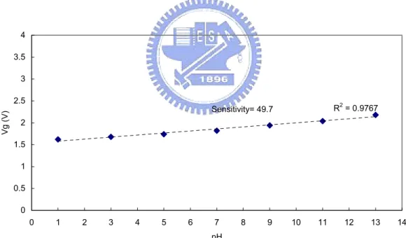
According to the result of measurement, the full range (pH 1 ~ pH 13) sensitivity is 49.7 mV/pH. The sensitivity in acid environment is down to 33.3 mV/pH and in base
environment is little higher at 60 mV/pH. The Id-Vg curve of ZrO2 is shown in Fig. 4-1,
and the sensitivity (pH versus gate voltage) chart is shown in Fig. 4-2.
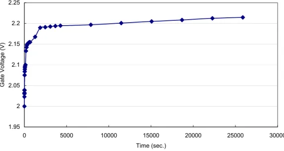
The drift rates of ZrO2 film for different pH and hysteresis width of the ZrO2-ISFET
for different pH loops are calculated by a constant voltage/ current circuit and a voltage-time recorder to measure the gate voltage of the ISFET. The results are shown in
Fig. 4-3 and Fig. 4-4. The drift of ZrO2 film is around 1.75 mV/ Hr and its
hysteresis/sensitivity ratio is about 96.4%.
4.2.2 Sensitivity, drift and hysteresis characteristics of HfO2 membrane
The I-V curve of HfO2 is shown in Fig. 4-5, and the sensitivity (pH versus gate
voltage difference) chart is shown in Fig. 4-6. The overall sensitivity is 45 mV/pH. The sensitivity in acid environment is down to 35 mV/pH and in base environment is much
higher at 55 mV/pH. The drift of HfO2 film is 1 mV/hr for specific pH and hysteresis width
hysteresis/sensitivity ratio is zero, which means almost no hysteresis phenomenon happens
of HfO2 film deposited by E-gun process.
4.2.3 Sensitivity and hysteresis characteristics of Al2O3 membrane
The I-V curve of Al2O3 is shown in Fig. 4-9, and the sensitivity (pH versus gate
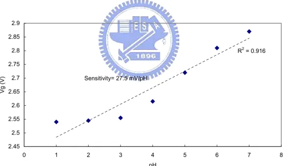
voltage difference) chart is shown in Fig. 4-10. The overall sensitivity is very low in the value of 27.5 mV/pH. The sensitivity in acid environment is down to 12.5 mV/pH and in base environment is up to 42.5 mV/pH. Fig. 4-11 shows the result of hysteresis, the hysteresis/sensitivity ratio is about 60%.
4.2.4 Sensitivity and hysteresis characteristics of TiO2 membrane
The I-V curve of TiO2 is shown in Fig. 4-12, and the sensitivity (pH versus gate
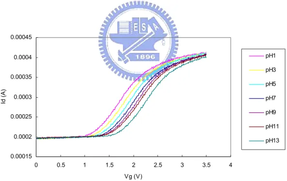
voltage difference) chart is shown in Fig. 4-13. The overall sensitivity is the value of 45 mV/pH. The sensitivity in acid environment is up to 50 mV/pH and in base environment is little lower at 40 mV/pH. The result of hysteresis/sensitivity ratio 63.2% is shown in Fig. 4-14.
4.2.5 Sensitivity, drift and hysteresis characteristics of Si3N4 membrane
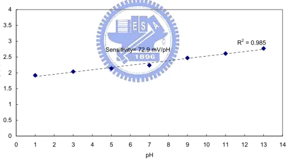
The I-V curve of Si3N4 is shown in Fig. 4-15, and the sensitivity (pH versus gate
voltage difference) chart is shown in Fig. 4-16. The overall sensitivity is 72.9 mV/pH. The sensitivity in acid environment is down to 53.3 mV/pH and in base environment is much
higher at 91.6 mV/pH. The hysteresis/sensitivity is 29.3% and drift of Si3N4 film is 1.25
mV/hr are shown in Fig. 4-17 and 4-18.
4.3 Comparison of Sensing Materials
4.3.1 Comparison of sensitivity and linearity characteristics
The characteristics of sensitivity, hysteresis/sensitivity ratio, and sensitivity of all films were summarized in Table 4-1. Nitride film has the highest sensitivity of 72.9 mV/pH and aluminum oxide has the lowest one of 27.5 mV/pH. Linearity which represents the stability of sensing films are obtained by linear regression, according to our experimental
result, TiO2 and Si3N4 have better performance of linearity than others. Al2O3 shows
unacceptable linearity characteristic due to its low sensitivity of acids.
Another observation is that ZrO2, E-gun prepared HfO2, Al2O3 and Si3N4 are with
better sensitivity performance in base environment than in acid, on the contrary, other films
such as sputtered HfO2 and TiO2 perform better sensitivity in acid environment. Shown in
Fig. 4-19 to Fig. 4-24.
Regarding the linearity, ZrO2 shows the most stable sensing capability than others
both in acid and base environment.
4.3.2 Comparison of hysteresis phenomenon
In our case, E-gun prepared HfO2 film shows excellent performance with almost no
hysteresis phenomenon happened. Even the film surface underwent post plasma treatment, (another experiment will be mentioned later), the film still showed the same result of
almost zero hysteresis. This time, ZrO2 shows unsatisfied result of 96.4%
hysteresis/sensitivity ratio, which means the chemical surface of ZrO2 is inadequate for
varied environments.
4.4 Discussion of NH
3plasma surface treatment
To get more stable characteristics of sensing membranes, post NH3 plasma treatment
was expected to modify the dangling bonds. The results are shown from Fig. 4-25 to Fig. 4- 30. Theoretically, the sensitivity, hysteresis and drift of sensing membranes should be decreased due to the reduction of bonding sites. But according to the experimental results, no significant changes in sensitivity, as shown in Fig. 4-31, but the linearity and
hysteresis/sensitivity ratio of most films are improved by post NH3 plasma treatment.
Shown in Fig. 4-32 and Fig. 4-33. Especially for TiO2 film, the hysteresis/sensitivity ration
was significantly improved from 63.2% to near 0%! Another observation is that although
the sensitivity changes slightly, but the sensitivity of some materials such as ZrO2, E-gun
HfO2 and Si3N4 become more ‘even’ in both acid and base environments as shown in Fig.
4-34. Recall the sensitivity theory:
0 2.3 B kT pH q α ∆Ψ = − ∆ (2-16) with 2 1 2.3 1 S S kTC q α β = +
where buffer capacity βS governed by the fixed number of oxide surface sites per area,
one possible explanation is that NH3 plasma surface treatment changes the distribution of
surface sites (
2
, ,
SiOH SiO SiOH
ν ν − ν +) so that sensitivity of acid and base behave differ from
4.5 Conclusions
The first purpose of our experiment is to study and obtain the most suitable material which CMOS fabrication compatible as sensing layer for ISFET. The other purpose is to find out the best pair materials for ISFET and REFET integration. For the first purpose, ISFET characteristics such as drift and stability are studied. For the second purpose, sensitivity dominates the application.
In this study, all sensing materials are available in CMOS fabrication technology; all
processes such thick oxide deposition, sensing film deposition and NH3 plasma treatment
are following the standard CMOS process rules.
pH-ISFET characteristics of drift, stability and sensitivity are governed by intrinsic buffer capacity and the differential capacitance which concerning the sensing layer materials. All the properties of oxide/ sensing layer interface, sensing layer/ electrolyte interface and sensing film itself impact the pH-ISFET characteristics. In our experiment, we designed several width/length ratio of channel under different process conditions such as sputter and e-gun deposition in order to find out the best CMOS fabrication compatible
sensing films. NH3 post plasma surface treatment has also been proven helpful for linearity
improvement for various sensing films in our study. All the results are summarized in Table 4-1.
Through the detailed overview of various CMOS fabrication compatible sensing films,
ZrO2, HfO2, Al2O3, TiO2 and Si3N4, we learned how to determine the proper films base on
different application requirements such as acid/base environment, pH measurement range and measurement timeframes etc.
Chapter 5
Future work
5-1 Future work
In our experiment, sensitivity, lineraity and drift phenomenon of various sensing materials were studied. Base on the observed result, aluminum oxide and nitride films have the most significant difference of pH sensitivity and they could be proper candidates for ISFET and REFET integration. Most of the attempts to create a REFET are based on covering the gate oxide of an ISFET with an additional ion insensitive membrane. Teflon seems as a good membrane material for REFET, however, it is not MOSFET fabrication compatible so that difficult of mass production with cheap standard MOSFET processes. Sensitivity is not the only consideration for ISFET and REFET integration, time-dependence of pH response, reproductivity and stability, hysteresis phenomenon, temperature and photoelectric impact, etc. are also important factors need to be clarified. Base on the knowledge of ISFET, glucose-sensitive enzyme field-effect transistor (ENFET) based on local pH change in biomembranes resulted from the formation of gluconic acid is also a proper extensive topic for future study.
Figure 1-1
Basic Structure and Operation of N-channel ISFETFigure 2-1
Figure 2-1 Operation principle of MOSFET
Figure 2-6 Potential profile and charge distribution at an oxide electrolyte solution interface
silicon
silicon
silicon
silicon silicon silicon silicon
Source
Drain
Gate
Reference
Electrode
Solution
Dark box
0.00E+00 5.00E-05 1.00E-04 1.50E-04 2.00E-04 2.50E-04 3.00E-04 3.50E-04 4.00E-04 4.50E-04 0 0.5 1 1.5 2 2.5 3 Vg(V) Id (A) pH1 pH3 pH5 pH7 pH9 pH11 pH13
Figure 4-1 Id-Vg characteristics of ZrO2 film on different pH values
R2 = 0.9767 0 0.5 1 1.5 2 2.5 3 3.5 4 0 1 2 3 4 5 6 7 8 9 10 11 12 13 14 pH Vg ( V ) Sensitivity= 49.7
1.95 2 2.05 2.1 2.15 2.2 2.25 0 5000 10000 15000 20000 25000 30000 Time (sec.) G a te V o ltage (V )
Figure 4-3 Drift characteristic of ZrO2 film
Hysteresis of ZrO2 film
1.2 1.4 1.6 1.8 2 2.2 2.4 0 5 10 15 20 25 30 Time Ga te Vo lta g e (V) pH=7 pH=7 pH=7 pH=7 pH=13 pH=13 pH=1 pH=1 Hysteresis H/S=96.4%
0.00025 0.0003 0.00035 0.0004 0.00045 0.0005 0.00055 0 0.5 1 1.5 2 2.5 3 3.5 Vg (V) Id (A) pH1 pH3 pH5 pH7 pH9 pH11 pH13
Figure 4-5 Id-Vg characteristics of HfO2 film on different pH values
R2 = 0.9644 0 0.5 1 1.5 2 2.5 3 3.5 4 0 1 2 3 4 5 6 7 8 9 10 11 12 13 14 pH Vg ( V ) Sensitivity= 45 mV/pH
1.97 1.98 1.99 2 2.01 2.02 2.03 2.04 2.05 2.06 0 5000 10000 15000 20000 25000 30000 Time (sec.) G a te V o ltage (V )
Figure 4-7 Drift characteristic of HfO2
Hysteresis of E-gun HfO2 film
1.7 1.8 1.9 2 2.1 2.2 2.3 2.4 2.5 2.6 0 5 10 15 20 25 30 Time Ga te Vo lta g e (V) pH=7 pH=7 pH=7 pH=7 Hysteresis H/S~0% pH=13 pH=13 pH=1 pH=1
0.0002 0.00025 0.0003 0.00035 0.0004 0.00045 0.0005 0.00055 0 0.5 1 1.5 2 2.5 3 3.5 4 4.5 Vg (V) Id (A) pH1 pH3 pH5 pH7 pH9 pH11 pH13
Figure 4-9 Id-Vg characteristics of Al2O3 film on different pH values
R2 = 0.916 2.45 2.5 2.55 2.6 2.65 2.7 2.75 2.8 2.85 2.9 0 1 2 3 4 5 6 7 pH Vg ( V ) Sensitivity= 27.5 mV/pH 8
Hysteresis of Egun Al2O3 film 2.5 2.55 2.6 2.65 2.7 2.75 2.8 2.85 2.9 2.95 3 0 5 10 15 20 25 30 Time G a te V o ltage (V ) pH=13 pH=13 pH=1 pH=1 pH=7 pH=7 pH=7 pH=7 Hysteresis 15mV H/S = 60%
Figure 4-11 Hysteresis phenomenon of Al2O3 film
0.00015 0.0002 0.00025 0.0003 0.00035 0.0004 0.00045 0 0.5 1 1.5 2 2.5 3 3.5 4 Vg (V) Id (A) pH1 pH3 pH5 pH7 pH9 pH11 pH13
R2 = 0.9898 0 0.5 1 1.5 2 2.5 3 3.5 0 1 2 3 4 5 6 7 8 9 10 11 12 13 14 pH Vg ( V ) Sensitivity= 45 mV/pH
Figure 4-13 pH sensitivity and linearity of TiO2 film
Hysteresis of E-gun TiO2 film
1.7 1.8 1.9 2 2.1 2.2 2.3 2.4 0 5 10 15 20 25 30 Time Ga te Vo lta g e (V) pH=13 pH=13 pH=7 pH=7 pH=7 pH=7 pH=1 pH=1 Hysteresis H/S=63.2%
0.00E+00 5.00E-05 1.00E-04 1.50E-04 2.00E-04 2.50E-04 3.00E-04 0 0.5 1 1.5 2 2.5 3 3.5 4 Vg Id pH1 pH3 pH5 pH7 pH9 pH11 pH13
Figure 4-15 Id-Vg characteristics of Si3N4 film on different pH values
R2 = 0.985 0 0.5 1 1.5 2 2.5 3 3.5 4 0 1 2 3 4 5 6 7 8 9 10 11 12 13 14 pH Vg ( V ) Sensitivity= 72.9 mV/pH
Hysteresis of Si3N4 film 2.2 2.4 2.6 2.8 3 3.2 3.4 1 2 3 4 5 6 7 8 9 10 11 12 13 14 15 16 17 18 19 20 21 22 23 24 25 26 27 Time Gat e Volt age (V) Hy steresis pH=13 pH=13 pH=7 pH=7 pH=7 pH=7 H/S=29.3% pH=1 pH=1
Figure 4-17 Hysteresis phenomenon of Si3N4 film
1.3 1.31 1.32 1.33 1.34 1.35 1.36 1.37 1.38 1.39 1.4 0 5000 10000 15000 20000 25000 30000 Time (sec.) Ga te Vo lta g e (V)
0 0.5 1 1.5 2 2.5 3 3.5 0 1 2 3 4 5 6 7 8 9 10 11 12 13 14
ZrO2 ZrO2 ZrO2 (NH3 treatment) ZrO2 (NH3 treatment)
R2 = 0.9945 R2 = 0.9956 R2 = 0.9923 R2 = 0.9927 Sensitivity= 50 mV/pH Sensitivity= 60 mV/pH Sensitivity= 52 mV/pH Sensitivity= 33.3 mV/pH
Figure 4-19 Sensitivity and linearity characteristics of ZrO2 in acid/base
0 0.5 1 1.5 2 2.5 3 3.5 0 1 2 3 4 5 6 7 8 9 10 11 12 13 14 pH Ga te Vo lta g e (V)
HfO2 (sputter) HfO2 (sputter) HfO2 (NH3 treatment) HfO2 (NH3 treatment)
Sensitivity= 37.5 mV/pH Sensitivity= 25 mV/pH Sensitivity= 55 mV/pH Sensitivity= 45 mV/pH R2 = 0.9956 R2 = 0.9652 R2 = 0.9653 R2 = 0.9956
0 0.5 1 1.5 2 2.5 3 0 1 2 3 4 5 6 7 8 9 10 11 12 13 14 pH Ga te Vo lta g e (V)
HfO2 (Egun) HfO2 (Egun) HfO2 (NH3 treatment) HfO2 (NH3 treatment)
Sensitivity= 45 mV/pH Sensitivity= 47.5 mV/pH Sensitivity= 55 mV/pH Sensitivity= 35 mV/pH R2 = 0.9705 R2 = 0.9985 R2 = 0.9552 R2 = 0.9854
Figure 4-21 Sensitivity and linearity characteristics of E-gun HfO2 in acid/base
0 0.5 1 1.5 2 2.5 3 3.5 4 0 1 2 3 4 5 6 7 8 9 10 11 12 13 14 pH Ga te Vo lta g e (V)
Al2O3 Al2O3 Al2O3 (NH3 treatment) Al2O3 (NH3 treatment)
Sensitivity= 37.5 mV/pH Sensitivity= 42.5 mV/pH Sensitivity= 16.5 mV/pH Sensitivity= 12.5 mV/pH R2 = 0.9152 R2 = 0.8076 R2 = 0.977 R2 = 0.763
0 0.5 1 1.5 2 2.5 3 3.5 0 1 2 3 4 5 6 7 8 9 10 11 12 13 14 pH Ga te Vo lta g e (V)
TiO2 TiO2 TiO2 (NH3 treatment) TiO2 (NH3 treatment)
Sensitivity= 56.5 mV/pH Sensitivity= 40 mV/pH Sensitivity= 45 mV/pH Sensitivity= 50 mV/pH R2 = 0.9823 R2 = 0.9963 R2 = 0.9736 R2 = 0.9987
Figure 4-23 Sensitivity and linearity characteristics of TiO2 in acid/base
0 0.5 1 1.5 2 2.5 3 3.5 4 0 2 4 6 8 10 12 14 pH Ga te Vo lta g e (V)
Si3N4 Si3N4 Si3N4 (NH3 treatment) Si3N4 (NH3 treatment)
Sensitivity= 91.6 mV/pH Sensitivity= 60 mV/pH Sensitivity= 53.3 mV/pH Sensitivity= 73.3 mV/pH R2 = 0.9886 R2 = 0.9993 R2 = 0.9782 R2 = 0.9979
Hysteresis of ZrO2 film (after NH3 treatment) 1.9 2 2.1 2.2 2.3 2.4 2.5 2.6 2.7 0 5 10 15 20 25 30 Time Gat e Volt age (V) pH=7 pH=7 pH=7 pH=13 pH=13 pH=1 pH=1 15mV H/S=26.1% Hysteresis
Figure 4-25 Hysteresis phenomenon of ZrO2 film after NH3 plasma treatment
Hysteresis of Sputtered HfO2 film (after NH3 treatment)
2.4 2.5 2.6 2.7 2.8 2.9 3 3.1 0 5 10 15 20 25 30 Time Gat e Volt age (V) pH=7 pH=7 pH=7 pH=7 pH=13 pH=13 pH=1 pH=1 Hysteresis H/S=68.5% 30mV
Figure 4-26 Hysteresis phenomenon of sputtered HfO2 film after NH3 plasma
Hysteresis of E-gun HfO2 film (after NH3 treatment) 1.2 1.3 1.4 1.5 1.6 1.7 1.8 0 5 10 15 20 25 30 Time Gat e Volt age (V) Hy steresis H/S~0% pH=7 pH=7 pH=7 pH=7 pH=13 pH=13 pH=1 pH=1
Figure 4-27 Hysteresis phenomenon of E-gun HfO2 film after NH3 plasma treatment
Hysteresis of E-gun Al2O3 film (after NH3 treatment)
2.25 2.3 2.35 2.4 2.45 2.5 2.55 2.6 2.65 2.7 2.75 0 5 10 15 20 25 30 Time Gat e Volt age (V) pH=13 pH=13 pH=1 pH=1 pH=7 pH=7 pH=7 pH=7 Hy steresis H/S~54.5%
Hysteresis of E-gun TiO2 film (after NH3 treatment) 1.2 1.3 1.4 1.5 1.6 1.7 1.8 1.9 2 0 5 10 15 20 25 30 Time Gat e Volt age (V) Hy steresis H/S~0% pH=13 pH=13 pH=7 pH=7 pH=7 pH=7 pH=1 pH=1
Figure 4-29 Hysteresis phenomenon of E-gun TiO2 film after NH3 plasma treatment
Hysteresis of Si3N4 film (after NH3 treatment)
2 2.1 2.2 2.3 2.4 2.5 2.6 2.7 2.8 2.9 3 0 5 10 15 20 25 30 Time Gat e Volt age (V) Hy steresis pH=13 pH=13 pH=7 pH=7 pH=7 pH=7 H/S=15.6% pH=1 pH=1
0 10 20 30 40 50 60 70 80
Sputter ZrO2 Sputter HfO2 E-gun HfO2 E-gun Al2O3 E-gun TiO2 Si3N4
Sensing films
Sensitivity
Raw NH3 plasma treatment
Figure 4-31 Sensitivity comparison of sensing films with/ without NH3 plasma post
surface treatment 86 88 90 92 94 96 98 100 102
Sputter ZrO2 Sputter HfO2 E-gun HfO2 E-gun Al2O3 E-gun TiO2 Si3N4
Sensing films
Linearit
y
Raw NH3 plasma treatment
Figure 4-32 Linearity comparison of sensing films with/ without NH3 plasma post