行政院國家科學委員會專題研究計畫 成果報告
寬頻增益平坦拉曼放大器及使用在超高速率波長多工傳輸
系統之研究(I)
計畫類別: 個別型計畫 計畫編號: NSC91-2215-E-009-054-執行期間: 91 年 08 月 01 日至 92 年 07 月 31 日 執行單位: 國立交通大學光電工程研究所 計畫主持人: 董正成 報告類型: 精簡報告 處理方式: 本計畫可公開查詢中
華
民
國 92 年 9 月 26 日
2
行政院國家科學委員會專題研究計畫成果報告
寬頻增益平坦拉曼放大器及使用在
超高速率波長多工傳輸系統之研究(I)
The study of br oadband/gain-flattened Raman amplifier s
and using in the ultr a-high WDM tr ansmission systems(I)
計畫編號:NSC 91-2215-E-009-054
執行期限:91 年 8 月 1 日至 92 年 7 月 31 日
主持人:董正成 助理教授 東華大學 電機工程學
系
一、中文摘要 本計劃在實驗及理論模擬上探討拉曼 放大器的特性,進行設計、製作出高增益 平坦化、寬頻譜的拉曼放大器,並實際架 設使用拉曼放大器之光纖傳輸系統。第一 年首先建立拉曼放大器多波道的模擬程 式,且對各種不同傳輸介質包括單模光 纖、色散位移光纖、色散補償光纖及非零 色散位移光纖等製作單一光源激發之拉曼 放大器,研究放大器在不同介質中的增益 特性及效益。在非零色散位移光纖實驗中 發現由激發光及信號光產生四波混合效 應,嚴重可達 3dB 增益減低。我們也探討 在色散補償光纖中的反射式拉曼放大器, 其拉曼增益有效的提升。 關鍵詞:拉曼放大器;增益平坦;波長多 工;色散補償;四波混合 Abstr actThis project is mainly to study the
Raman amplifiers theoretically and
experimentally. We will design the
broadband and gain-flattened Raman
amplifier and erect the ultra-high bitrate fiber transmission systems by using the Raman amplifiers. In the first year, we will build up the simulation program of the Raman
amplifier which considers the
multi-wavelength pumping unit with the multi-longitude mode spectrum. The Raman amplifiers with single wavelength pumping are set up in different media such as single-mode fiber, dispersion shift fiber, dispersion compensation fiber, and non-zero dispersion shift fiber. The gain characteristic and efficiency are studied. We observed experimentally four wave mixing (FWM) between 14xx nm pump and 15xx nm signal in a forward-pumped distributed Raman amplifier over non-zero dispersion shifted fiber. The FWM efficiency determined by the fiber group delay or dispersion characteristics
was investigated in this work. The
suppression of Raman gain about 3 dB was observed with peak four-wave mixing. We also demonstrate the characteristics of the
reflective type distributed Raman amplifier in the dispersion compensating fiber which is composed of a circulator and a Faraday rotator mirror. With the same dispersion compensation, the gain of the reflective type is higher than that of the conventional single-pass type
Keywor ds: Raman amplifier, Gain flatten,
Wavelength division multiplexing, Dispersion compensation, Four wave mixxing
二、前言
Distributed Raman amplification (DRA) has the potential to extend the span length and the number of wavelength division multiplex (WDM) channels for a high capacity long haul optical transmission system. It provides wide band (∼100 nm) amplification of the optical signal in the transmission fiber using multiple high power pumps of different wavelengths, about 100 nm shorter than that of the wide spectral width of the WDM carrier wavelengths. Back-pumped DRA has been widely used in transmission system experiments [1, 2], providing an equivalent lump amplifier noise figure < 0 dB [3] and reducing the pump noises as averaged by the forward traveling signal. Whereas forward-pumped DRA allows the launched signal power to be reduced which lessens the impact of optical nonlinearities on the transmission system [4]. Bidirectional pumped DRA has the potential to provide more uniform Raman gain to overcome the fiber loss, which then reduces signal power for a given transmission span loss and mitigates fiber nonlinear effects [5].
Dispersion compensation technique is necessary to increase transmission distance in high bit rate (10 Gbit/s or more) systems. The use of dispersion compensating fiber (DCF) is a popular way to upgrade installed links made of anomalous dispersion transmission fiber [6,7]. However, DCF devices exhibit
significant insertion loss, previous
transmission experiments incorporating DCF used to use the erbium-doped fiber amplifiers to offset the insertion loss [8]. Raman amplification has also been shown to be an
effective means of compensating for the loss
of DCF [9,10]. Distributed Raman
amplification in the transmission fiber is a powerful technology for improving the system performance of optical transmission systems over lumped amplification. The use of distributed Raman amplifier in fiber spans can improve optical signal-to-noise ratio
(OSNR) and decrease the effect of
nonlinearity in transmission systems [11]. As the bit rates increase (40 Gbit/s and higher), the polarization mode dispersion (PMD) is becoming a major system impairment [12,13]. Owing to its statistical nature, the PMD appears to be a complex phenomenon limiting the performance of transmission system. The PMD splits pulses into two pulses polarized along two orthogonal directions with the statistical ensemble average of differential group delay and hence signal distortion [14].
三、研究目的
We investigated nondegenerated FWM between two of the pump Fabry-Perot (FP) wavelengths around 14xx nm and the single-wavelength probe signal around 15xx nm to generate unwanted FP spectra adjacent to the 15xx nm probe signal. The pump Fabry-Perot spectra centered at 1440, 1450
and 1460 nm were experimentally
reproduced via efficient FWM around the 1-mW single-wavelength probe signal at 1558, 1548, and 1538 nm respectively. The suppression of DRA on/off gain by about 2 to 3 dB was experimentally observed as FWM was maximized for reproduction of FP spectra at minimum phase mismatching between 2 FP pump wavelengths and 2 signal
wavelengths. The Raman-enhanced
pump-signal FWM was observed in [8] at various pump powers >155 mW, more pump powers leading to more direct amplification of the FWM noise. In our forward-pumped DRA with three pumps each operating at a low pump power of 100 mW, more FWM were observed with lower dispersion pump (1460 nm) and signal (1538 nm) wavelengths closer to the fiber zero dispersion wavelength (1497 nm). The DRA gain suppression together with the reproduced FP spectrum at 15xx nm signal band may limit the
usefulness of the forward pumped DRA, generating spectrally nonuniform FWM induced noise floors and crosstalk in WDM fiber optic transmission systems. In the DCF, employing a circulator and a Faraday rotator mirror (FRM), we measure the gain and noise figure of the reflective type distributed Raman amplifier. With the same dispersion compensation, the gain of the reflective type dispersion compensating Raman amplifier (DCRA) is higher than that of the conventional single-pass type dispersion compensating Raman amplifier. The forward pumping is better than the backward pumping in the reflective type DCRA. By using the reflective type configuration, the PMD of reflective type DCRA is almost compensated.
四、結果與討論
Fig. 1 shows the experimental setup. The probe signal was from a mode-locked laser tunable from 1520 to 1600 nm with relative intensity noise of –145 dB/Hz. Three high power (100 mW) pump laser diodes
(LDs) have multiple FP wavelengths
respectively centered at 1440, 1450, and 1460 nm. These three pump lasers were combined in a pump combiner and then coupled to a reflection type micro-optic WDM coupler for forward pumping to a 50 km NZDSF having mode field area Aeff =
73.7 ìm2 and 1497 nm zero dispersion
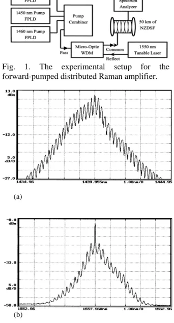
wavelength, providing distributed Raman gain for the 15xx nm signal. Fig. 2(a) is the FP spectrum of the1440 nm pump laser with a 0.225 nm mode spacing. For a 100-mW pump at 1440 nm forward traveling through the 50 km NZDSF with 1-mW probe signal, the output signal spectrum in Fig. 2(b) shows FWM reproduced FP spectra with the single wavelength signal centered at 1558 nm.
With a 15xx nm tunable probe signal of 1 mW co-propagating with the 100 mW pump, the on/off distributed Raman gain spectra in Fig. 3 was obtained from the ratio of the measured fiber output powers with the pump being turned on and off. There was a dip about 2 to 3 dB in the on/off Raman gain spectra associated with peak FWM at 1558, 1548, and 1538 nm for 1440, 1450, and 1460 nm pumps respectively. The on/off Raman
gain peak for each pump wavelength is shifted from the pump wavelength by about 100 nm, having peak gain 3.6 dB, 3.5 dB and 3.3 dB at wavelength of 1540, 1550, and 1560 nm obtained from a 100 mW pumping individually at 1440, 1450, and 1460 nm respectively.
The on/off peak Raman amplification is ) 2 exp( 0 eff p eff R A A L P g G =
where gR is the peak Raman gain coefficient,
P0 is the pump power at the amplifier input,
and the pump effective length LPeff is given
by LPeff = (1-exp(-αPL))/αP. The factor 1/2 in
the exponent is due to random polarization angle between pump and signal, spectrally
separated by ≅ 100 nm, during their
propagation in the 50 km fiber. With gR =
7.4x10⁻¹⁴ m/W for the 1450 nm pump, Po =
100 mW, αP = 0.26 dB/km, L = 50 km, LPeff
= 15.9 km, and Aeff = 73.7 µm2, the peak
amplification is GA = 2.22 or 3.46 dB which
is very close to the measured gain of 3.5 dB in Fig. 3.
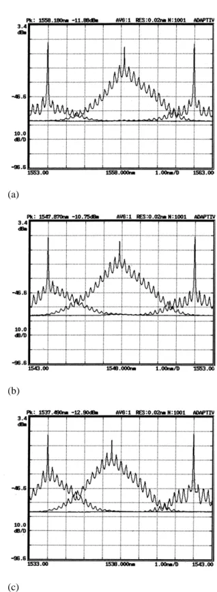
For a 100 mW pump at 1440 nm forward traveling through the 50 km NZDSF with the 1 mW single-wavelength probe signal, the three output signal spectra in Fig. 4(a) show the additional side lobes at the probe single-wavelength signal centered at 1554, 1558, and 1562 nm due to FWM of the pumps and signal. Fig. 4(b) is the same as Fig. 4(a) except it is for the 1450 nm pump of 100 mW co-propagating with probe signal centered at 1544, 1548, and 1552 nm, while Fig. 4(c) is for the 1460 nm pump of 100 mW and the probe signal centered at 1534, 1538, and 1542 nm. It is interesting that the FP signal spectra associated with most efficient FWM and the corresponding FP pump spectra were spectrally separately by 118, 98, and 78 nm respectively in Fig. 4(a), (b), and (c), solely determined by the fiber group delay and dispersion characteristics to be discussed latter. The reproduction of FP spectra in the 15xx nm signal band via FWM was not observed for the single-mode fiber (SMF28), dispersion shifted fiber (DSF), and dispersion compensated fiber (DCF) with zero dispersion wavelengths at 1310, 1547, and 1710 nm respectively. This is in drastic
contrast with the forward pumped DRA with
the NZDSF having zero dispersion
wavelength of 1497 nm, reproducing FP pump spectra in the 15xx nm signal band via FWM.
To further support our understanding of the phase mismatching in FWM, the chromatic dispersion and the group delay (solid lines) vs. wavelength in Fig. 5 were measured by the optical network analyzer from 1525 to 1635 nm for a 300 m long NZDSF. The zero dispersion wavelength of 1497 nm is just the wavelength for minimum group delay. The group delays (solid square) at 14xx nm in Fig. 5 were inferred from that of the corresponding signal wavelengths at 15xx nm obtained from maximization of FWM efficiency for reproduction of FP spectra to be discussed latter, showing the group delays at pump wavelengths of 1440, 1450, and 1460 nm to be the same as that of the signal wavelengths of 1558, 1548, and 1538 nm respectively. Since the measured dispersion vs. wavelength seems linear, we made a linear extrapolation to the shorter wavelength down to 1440 nm and obtained a zero dispersion wavelength of 1497 nm
consistent with the manufacturer
specification of 1497.3 nm.
Table I also shows that less FWM efficiency = 2.2x10⁻⁴ and 1.9x10- 4 are associated with more phase mismatch ∆β = 4.1 km-1 and -4.3 km-1 respectively for the probe single wavelength signals at 1554 and 1562 nm. Thus there was less number of FP wavelengths generated and a negligible dip in DRA gain in Fig. 4(a).
For the pumps at 1450 and 1460 nm, maximum FWM for reproduction of FP spectra was experimentally observed as in Fig. 4(b) and (c) at 1548 and 1538 nm respectively. This in turn implies that the group indices at 1450 and 1460 nm are identical to that at 1548 and 1538 nm respectively, solely determined by the NZDSF group delay characteristics.
The schematic diagrams of the DCRA, which provides dispersion D = -1326 ps/nm at a wavelength of 1544.5 nm, are shown in Fig.6. Fig.6(a) shows the conventional
single-pass 15.5 km DCRA which
incorporates an isolator and a wavelength
division multiplexing (WDM) coupler in the input, allowing forward pumping. The 7.75 km reflective type DCRA using forward pumping configuration is shown in Fig.6(b). An optical circulator is placed between the isolator and the WDM coupler connected to one end of the DCF. The optical circulator has a loss of about 0.7 dB and an isolation of over 47 dB. A FRM at the other end of DCF reflects back the signals. The reflectivity of the FRM is 94%. The FRM, having a 45° single-pass rotation and reflector mirror,
reflects the light in the orthogonal
polarization state regardless of the incident state. The state of polarization (SOP) in the backward direction is orthogonal to that in the forward direction everywhere regardless of any fiber birefringence. The reflected light then makes a second pass through the DCF. As a result, the dispersion compensation value is the same for the two configurations. We use two laser diode modules at a wavelength of 1440 nm. Each laser is stabilized by a fiber Bragg grating, and is orthogonal polarization with polarization beam combiner.
The measured results of forward pumping by scanning the wavelength of input signal with intensity of –10 dBm are shown in Fig.7. We measure signal gains of both the reflective type and the single-path configuration. Even though the reflective type DCRA includes the extra losses of a circulator and a reflecting mirror, the net gains of the reflective type DCRA are still higher than those of the single-pass DCRA over the whole wavelength regime. The net gains at the wavelength 1538 nm are 7.54 dB and 0.82 dB for the reflective-type and the single-pass, respectively. For the reflective type DCRA, the reflective signals by FRM will interact with higher pump power than the signals propagating through 7.75 km to 15.5 km in the single-pass DCRA. The product of the pump power and the Raman gain coefficient determines the gain of the signal. Therefore, the gains of the reflective type surpass those of the single-pass. The noise figure characteristics of the DCRAs are also illustrated in Fig.7. They have the similar noise figures. At shorter wavelengths of the signal, the noise figures of the
reflective type are slightly higher than those of the single-pass because the losses of
circulator are increased at shorter
wavelengths. Thus for the forward pumping, the reflective type DCRA is better than the single-pass DCRA.
We use the Poincaré sphere method to measure the PMDs of the single-pass DCRA and the reflective type DCRA with a FRM. The Poincaré sphere method is based on the evolution of the SOP as a function of frequency and measures the differential group delay between the principal SOP. The
τ (PMD) can be obtained by τ=ds dω , where s and ω are the stokes vector on the
Poincaré sphere and the angular frequency, respectively. The tunable laser of fixed polarization state is used as a light source. We tune the wavelength of light source and measure the stokes vector of polarization state after DCRA with polarimeter to obtain the PMD values. Fig. 8 shows the stokes vector S2 versus input wavelength. From the
stokes vector measurements, the PMD values are 0.27 ps and 0.05 ps for the single-pass DCRA and the reflective type DCRA with a FRM, respectively. Therefore, with a FRM in the reflective type DCRA, the PMD of DCF is completely compensated but the survived PMD 0.05 ps is all from the circulator. If we replace a FRM with a reflective mirror in the reflective type DCRA, the PMD value is 0.31 ps.
五、計畫成果自評
This project has been performed thoroughly. The results are outstanding in the
respects of the use of dispersion
compensation fiber and non-zero dispersion shift fiber in transmission systems. Peak FWM for reproduction of FP spectra was observed for mixing the FP modes of 1440, 1450, 1460 nm pumps respectively with 1558, 1548, and 1538 nm signals in a forward pumped DRA over a 50 km NZDSF with a zero dispersion wavelength at 1497 nm. This is the consequence of minimum phase mismatch for FWM due to equal group delay for the pump and its corresponding signal wavelength, solely determined by the fiber group delay or dispersion characteristics. The
pump wavelength (1460 nm for example) closer to 1497 nm with smaller fiber dispersion and high phase matching will have the largest FWM efficiency around the signal wavelength (1538 nm correspondingly). For the reflective type DCRA, the signal experiences more pump power, the gain is higher than that of the conventional single-pass DCRA with the same dispersion compensation. Moreover, using a FRM in the reflective type DCRA is an easy and beneficial implement to compensate for the PMD in DCF.
六、參考文獻
[1] Haxell, N. Robinson, A. Akhtar, M. Ding, and R. Haigh, “2410 km all-optical network field trial with
10Gb/s DWDM transmission,”
OFC’2000, PD41-1, 2000.
[2] F. Koch, S. V. Chernikov, S. A. E. Lewis, and J. R. Taylor, “Characterisation of single stage, dual-pumped Raman fibre amplifiers for different gain fibre lengths,” Electron. Lett., vol. 36, pp. 347-348, 2000.
[3] P. B. Hansen, L. Eskildsen, A. J. Stentz, T. A. Strasser, J. Judkins, J. J. Demarco, R. Pedrazzani, and D. J. DiGiovanni, “Rayleigh scattering limitations in distributed Raman pre-amplifier,” IEEE Photon. Technol. Lett., vol. 10, no. 1, pp. 159-161, 1998.
[4] R. P. Espindola, K. L. Bacher, K. Kojima, N. Chand, S. Srinivasan, G. C. Cho, F. Jin, C. Fuchs, V. Milner, and W.
C. Dautremont-Smith, “Penalty-free
10Gbits/s single-channel co-pumped distributed Raman amplification using low RIN 14xx nm DFB pump,” Electron. Lett., vol. 38, pp.113-115, 2002.
[5] N. Takachio and H. Suzuki,
“Application of Raman-distributed
amplification to WDM transmission
systems using 1.55-µm
dispersion-shifted fiber,” J. Lightwave Technol., vol. 19, no. 1, pp. 60-69, 2001.
[6] N. Kikuchi, S. Sasaki, and K. Sekine, "10 Gbit/s dispersion-compensated transmission over 2245 km conventional
fibers in a recirculating loop," Electron. Lett., 31, pp. 375-377(1995).
[7] F. Futami, K. Taira, K. Kikuchi, and A. Suzuki, "Wideband fibre dispersion equalisation up to forth-order for
long-distance subpicosecond optical
pulse transmission," Electron. Lett., 35, pp. 2221-2223(1999).
[8] H. Nakano, and S. Sasaki,
"Dispersion-compensator incorporated optical fiber amplifier," IEEE Photon. Tech. Lett., 7, pp. 626-628(1995).
[9] P. B. Hansen, G. Jacobovitz-Veselka, L. Grüner-Nielsen, and A. J. Stentz,
"Raman amplification for loss
compensation in dispersion
compensating fiber modules," Electron. Lett., 34, pp. 1136-1137(1998).
[10] Y. Emori, Y. Akasaka, and S.
Namiki, "Broadband lossless DCF using
Raman amplification pumped by
multichannel WDM laser diodes,"
Electron. Lett., 34, pp.
2145-2146(1998).
[11] P. B. Hansen, L. Eskildsen, S.
G. Grubb, A. J. Stentz, T. A. Strasser, J. Judkins, J. J. DeMarco, R. Pedrazzani, and D. J. DiGiovanni, "Capacity upgrades of transmission systems by Raman amplification," IEEE Photon. Tech. Lett., 9, pp. 262-264(1997).
[12] C. D. Pool and J. Nagel,
"Polarization effect in lightwave
systems," in ‘Optical Fiber
Telecommunications IIIA’, Academic Press, New York(1997).
[13] D. Sobiski, D. Pikula, J. Smith,
C. Henning, D. Chowdhury, E. Murphy, E. Kolltveit, and F. Annunziata, "Fast first-order PMD compensation with low insertion loss for 10 Gbit/s system," Electron. Lett., 37, pp. 46-48(2001).
[14] N. Gisin, R. Passy, and J. P.
Von Der Weid, "Definition and
measurement of polarization mode dispersion: interferometric versus fixed analyzer methods," IEEE Photonics Technol. Lett., 6, pp. 730-732(1994).
Fig. 1. The experimental setup for the forward-pumped distributed Raman amplifier.
(a)
(b)
Fig. 2. (a) The Fabry-Perot spectrum of the 1440 nm pump laser, and (b) FWM reproduced output spectra of a 1440 nm pump with single wavelength signal centered at 1558nm.
Fig. 3. The on/off The on/off distributed Raman gain spectra for 1440, 1450, and 1460 nm pump wavelengths with each of the 100 mW pump power co-propagated with a 1 mW of 15xx nm signal. The Raman gain was obtained from the ratio of the measured fiber output powers with the pump being turned on and off.
(a)
(b)
(c)
Fig. 4. FWM reproduced spectra for a 100 mW pump power forward traveling with 1 mW single-wavelength probe signal through a 50 km
non-zero dispersion shifted fiber with zero dispersion wavelength of 1497 nm. (a) 1440 nm pump with the probe single wavelength signal centered at 1554, 1558, and 1562 nm, (b) 1450 nm pump with probe signal centered at 1544, 1548, and 1552 nm, and (c) 1460 nm pump with the probe signal centered at 1534, 1538, and 1542 nm.
Fig. 5. The dispersion and relative group delay of a 300 m of NZDSF. The solid line measured by an optical network analyzer and the solid squares are the results inferred from the maximum FWM efficiency for reproduction of FP spectra. The dashed line is a linearly extrapolated dispersion vs. wavelength.
Table I. Estimated values of the phase mismatch
∆β and the FWM efficiency η for (λp = 1440 nm, λs = 1554, 1558, and 1562 nm), (λp = 1450 nm, λs = 1544, 1548, and 1552 nm), and (λp = 1460
Fig.6. Schematic diagrams of DCRA. (a) the conventional single-pass, (b) the reflective type configuration.
Fig.7. The measured net gain and noise figure of forward pumping; n: gain of 7.75 km reflective type DCRA, ¨: noise figure of 7.75 km reflective type DCRA, 5: gain of 15.5 km single-pass DCRA, ∆: noise figure of 15.5 km single-pass DCRA.
Fig.8. The measurement of stokes vector S2
versus input wavelength to obtain the PMD values. Tunable Laser Pump unit WDM Output (a) 15.5 km Tunable Laser Circulator WDM (b) Pump Unit FRM Output 7.75 km -15 -10 -5 0 5 10 1515 1525 1535 1545 1555 1565 1575 Wavelength (nm) Gain (dB) 3 5 7 9 11 13 15 Noise Figure (dB)
PMD measurement of single-path DCRA (=0.27 ps)
0 0.1 0.2 0.3 0.4 0.5 1535 1536 1537 1538 1539 1540 1541 1542 S2
PMD measurement of reflective type DCRA (=0.05ps)
0.1 0.2 0.3 0.4 1525 1529 1533 1537 1541 1545 1549 Wavelength (nm) S2