216 IEEE/ASME TRANSACTIONS ON MECHATRONICS, VOL. 1, NO. 3, SEPTEMBER 1996
Integrating
Fuzzy
National Tai
Li-Ren Lin and Han-Pang Huang, Member, IEEE
Abstruct- Compared to traditional tendon-driven robots, the mechanism design of the National Taiwan University hand' has an uncoupled configuration and is compact in size
[lo].
In this paper, a specially designed compact control system, which isembedded into the NTU hand to satisfy the limited space, is developed to perform the control of the five-finger robot with 17 degrees of freedom (DOF). There are total 17 actuators including transmission mechanism, 17 potentiometers, and 18 tactile sensor pads to be integrated. Those 17 actuators should be controlled simultaneously by integrating 17 position sensing signals and 18 tactile signals. Multi-loop position control is further complicated by multi-loop force control as well as sensor integration. The proposed control system distributes the computation load into several modules and utilizes the DSP chip. It takes advantage of the fuzzy control by introducing the knowledge of human and sensor fusion with the finger joint and tactility. Using the communication function of the control system, the knowledge bases can be loaded for high level computation and modified during run time.
I. INTRODUCTION
HE operation of multifingered robot hands for fine motion
T
and dexterous manipulation is an interesting topic in research and applications of robotics. The multifingered robot acts as a multipurpose gripping device for various tasks. Since most multifingered hands are designed to replace some work of human hands, they duplicate the shape and function of human hands. In order to manipulate various objects and tools, dexterity is the first requirement for the multifingered robots. In addition to the dexterous manipulation, the ability to perform a power grasp is also required. The size of the hand is a significant part in research. A compact enough multifingered robot can be directly attached to the end of an industrial robot arm, or play a role in prosthetics.A. Related Works
Many multifingered robot hands have been developed [7], [17], [19], [20]. The number of fingers ranges from three
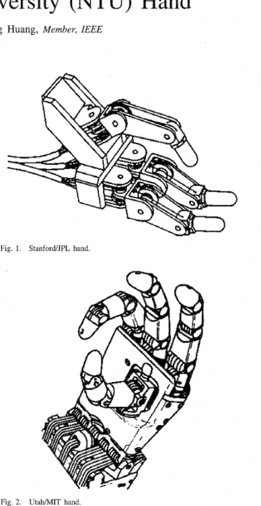
to five. An example of the three-fingered robot hand is the JPWStanford hand shown in Fig. 1 [18]. Each finger of that hand has three DOF's (degrees of freedom) and is driven by four motors through tendon cables. Two parallel axis joints 'NTU hand holds a patent of Taiwan, R.O.C. under Patent no. 107 115. (NTU is the abbreviation of National Taiwan University.)
Manuscript received May 1, 1996; revised July 5, 1996. This work was supported in part by National Science Council, Taiwan, R.O.C., under Grant NSC 84-2212-E002-032.
The authors are with the Robotics Laboratory, Department of Mechanical Engineering, National Taiwan University, Taipei, Taiwan 10674, R.O.C.
Publisher Item Identifier S 1083-4435(96)07322-X.
Fig. 1. StanfordJPL hand.
/"n
Fig. 2. Utah/MIT hand.
provide rotation, and the third proximal joint, perpendicular to the other joints, provides the sideward motion. Due to large number of motors and strong coupling in the tendon configuration, the control system of the JPL/Stanford hand is very complicated. In addition, it is difficult to perform calibration by using the tension of four cables in a finger.
The U t a M I T hand shown in Fig. 2 [7] has one thumb and three fingers. Each finger of the hand has four joints.
LIN AND HUANG INTEGRATING FUZZY CONTROL OF THE DEXTEROUS NTU HAND 217
n
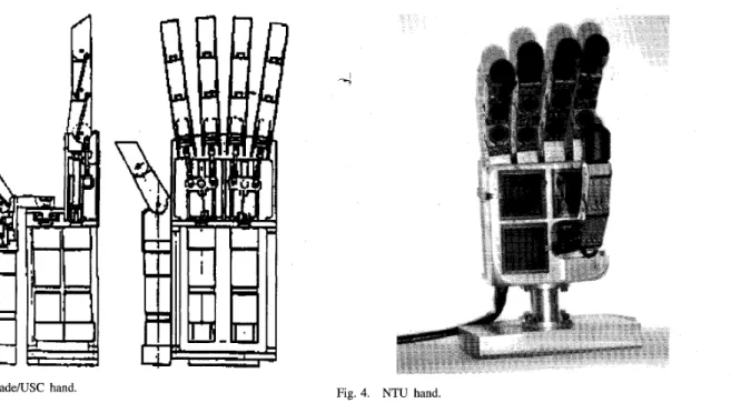
Fig. 3. BelgradeRJSC hand.
Three parallel joints provide the rotation and the proximal joint supplies the lateral action. Since the Utah/MIT hand has four DOF’s in each finger, eight independent tendons and pneumatic cylinders are required. Each pair of tendons must keep tension to maintain the joint of the robot finger. Once a lateral motion is performed, one joint is activated and the other three joints keep stationary so that tensions on eight tendons must be recalculated. The coupling problem also causes the Utah/MIT hand to use a large number of actuators and a complex control system [16]. The above two fingered hands are bulky because of their tendon driven configurations and associated control systems.
The BelgradeLJSC hand shown in Fig. 3 [19] has five
fingers and four motors, two motors for the thumb and two for the other fingers. Each finger has three parallel axis joints but only one DOF. The hand only provides simple grasping capacity rather than dexterous manipulation. The multifingered robot of Yaskawa electric corporation has three fingers and nine DOF’s [20]. This hand only utilizes its fingertip because of its bulky cylinder finger segments. The above two hands are not suitable candidates for prosthetics.
The control of the multifingered robot hand is very com- plicated [ 161 because the DOF’s of the multifingered robot hand are too many and the dynamics of the hand are highly nonlinear and coupled. Once the tactile sensors are introduced, it becomes a much more complex control problem that deals with both position and force.
In literature, many research works deal with the problem of position and force control. A typical approach is the hybrid positiodforce control [ 151. In this method, the control problem is divided into a set of position and force constraints that depend on the mechanical and geometrical features of the task to be performed. In general, this control scheme performs well for simple surface geometry, but it needs more modifications and advanced strategies to handle complex surfaces. The impedance control is designed to track the relation between
Fig. 4. NTU hand.
the velocity of the manipulator and the interaction forces in order to generate compliant motion [5]. This method is not appropriate for the application requiring a desired contact force trajectory; in particular, it results in oscillatory motion due to the introduced environmental stiffness.
Since Zadeh’s paper on fuzzy set [22], fuzzy control has become one of the most active and fruitful areas in the applications of fuzzy set theory. Most fuzzy logic control relies on the operators’ experiences to design the knowledge bases since the pioneering work of Mamdani [ l l ] . The adaptive fuzzy system equipped with a training algorithm is also applied to the control problem [8], [14], [21]. Due to the self-organized
mechanism, the adaptive fuzzy control can resolve system uncertainty with less heuristic information. In the research of Bekey [ 11, a knowledge-based planner was proposed to select grasping postures by reasoning from symbolic information of the target object geometry and the nature of the task. However, the knowledge about grasping in the sense of control was not discussed.
B. Overview
This paper is organized into three parts: mechanism design, fuzzy control strategy and control system. The first part shows a new approach to design and implement a dexterous artificial hand: the NTU hand. The NTU hand is designed so that it is potential use for both robotics and prosthetics applications. The design of the NTU hand is shown in Fig. 4. Due to the design of an uncoupled mechanism, each finger and joints of the NTU
hand are all individually driven. Hence, the dexterity of the NTU hand can be obtained from the uncoupled arrangement. Based on the idea of design for manufacture and design for control, the kinematics and dynamics of the NTU hand turn out to be simple.
The second part of this paper deals with the fuzzy control of the multifingered robot hand. An adaptive fuzzy control algorithm is proposed to carry out the simultaneous control
21s IEEEIASME TRANSACTIONS ON MECHATRONICS, VOL. 1, NO. 3, SEPTEMBER 1996
Fig. 5. Locations of 18 sensor pads.
of both the force and position. The linguistic knowledge bases of grasp are embedded with the fuzzy control. The fuzzy approximation is also introduced for the self-organized mechanism to improve the performance of grasping.
In the last part of this paper, the specifically designed control system for the NTU hand is introduced. We combine the advantages of the digital system and analog circuit to perform the large computation of the control scheme and sensor integra- tion. The adaptive fuzzy controller is implemented in DSP chip and gives satisfactory results. The results of the simulation and experiment are presented. Finally, the conclusions are made.
11. MECHANISM DESIGN
Many multifingered hands are driven by tendon cables. One reason is that cables act as muscles of human hands. Another reason is that actuators, reduction gears and sensors can be remotely installed to keep the hand itself compact. However, all traditional hands suffer from bulky mechanism and are inconvenient for practical applications. In this paper, a modular design is proposed to design the NTU multifingered robot hand
so that its driven mechanism is uncoupled and its size is good for both industrial and prosthetic applications.
Our goals of the mechanism design are several folds. The first goal aims to the functionality purpose; i.e., numbers of fingers and DOF's. It is known that three hard fingers are required for a force closure grasp of a two-dimensional object, and four fingers are required to grasp a three-dimensional object [12]. Although the number of fingers can be reduced by one with a suitable and realistic model of the fingertip under the same conditions [13], a human hand is always the design goal.
The second goal is the size. The hand including the overall driven mechanism should be about the same size as the human
Fig. 6. Human hand [3].
hand. Limitation of the size makes the hand suitable for robotics and rehabilitation applications. Once all parts are packed in the hand itself, the hand can be easily attached to the wrist of an industrial robot or to the prosthetic patients.
The next goal focuses on fabrication and maintenance. If the same parts can be repeatedly used in the modular design of the hand, the number of types of parts will be reduced and the cost will be down. Once the fingers are independent and exchangeable, the maintenance simply means to replace the damaged finger assembly without recalibration of the whole system.
The last goal deals with the potential of improvement. The performance can be enhanced by replacing the parts whenever better materials are available. But, the main design is preserved. Once the materials of transmission or the power of actuators are improved, the performance of the hand is also enhanced.
Based on the above design goals, the NTU hand has five fingers with 17-D DOF's. Both the thumb and the first finger have four joints; two at the knuckle, one between the proximal and middle finger segments, and one between the middle and distal finger segments. Other fingers have three joints; but only one at the knuckle. Each finger is equipped with tactile sensors to detect grasping force. Due to cost and practical implementation, the tactile sensors are attached to the inner sides of finger segments and the palm, as shown in Figs. 4 and 5. The concept and design details will be discussed in the subsequent sections.
LIN AND HUANG: INTEGRATING FUZZY CONTROL OF THE DEXTEROUS NTU HAND
~ ~~
1. Finger tip
2. Base of the finger tip 3. s m
4. Shell of the finser segmenr
5A. k r m i n A ( % : l ) SB.GeartrainB(812:l)
1 5A
6. Cover of the finger segment
7. High pnfomance micm motor
8. Gear on the shaft of motor
9. Seat of the motor
IO. Position enso or
11. Tactile senwr
A. Hand Mechanism
The idea of design is obtained from the human hand. Since the structures of the fingers of the human hand are almost the same and independent, as shown in Fig. 6, this feature gives us the idea to design the hand beginning with the finger and to simplify the development. The human finger consists of several finger segments. This fact also gives us the inspiration to design independently driven finger segments for a complete finger. The auxiliary devices for the artificial finger are also required for the lateral motion, as the function of muscles in the palm.
1) Finger and the Finger Segment: The finger of the NTU hand consists of the distal segment, the middle segment, the proximal segment, and the base finger segment. To ease the manufacture and assembly, the group technology is applied to the design of the fingers and finger segments. The design should avoid the coupling problem of tendon driven structure and limit the size to make it easy for applications. Since we use a modular design, each finger is composed of finger segments. Once an individual finger is constructed, the mechanism of the whole robot hand Is almost complete. In order to meet the requirements of the independently driven fingers, it is essential to design a finger with all the equipped parts.
The finger design is shown in Fig. 7. Each finger segment, except the distal segment, contains one high performance micro motor that drives a set of specially arranged gear trains to rotate the previous finger segment. The gear ratio of the middle and proximal finger segments is about one hundred, but the gear ratio of the base segment is about one thousand for the sake of heavy loads. The position sensor of each joint is installed in each finger segment. It is a potentiometer which is driven by the gear within the gear trains, and is proportional to the angle of the finger joint.
There are many electrical wires in the inner space of each segment shell, the placement of sensors and motors must be taken into account during the assembly process. Since the position sensor is driven by gear within the gear trains, its calibration must be accomplished during the assembly process.
219
Pressure
0.1 psi I 1 psi I1.0psi 110.0pd
Typical response curve:
2.5 cm diameter device 1.25 cm diameter flat metal p m k
I O g 100 g I Kg 10 Kg
0 4 02 3 5 oz 2 2 Ibs 22 0 Ibs
Force
Fig. 8. FSR forcehesistance characteristics [4].
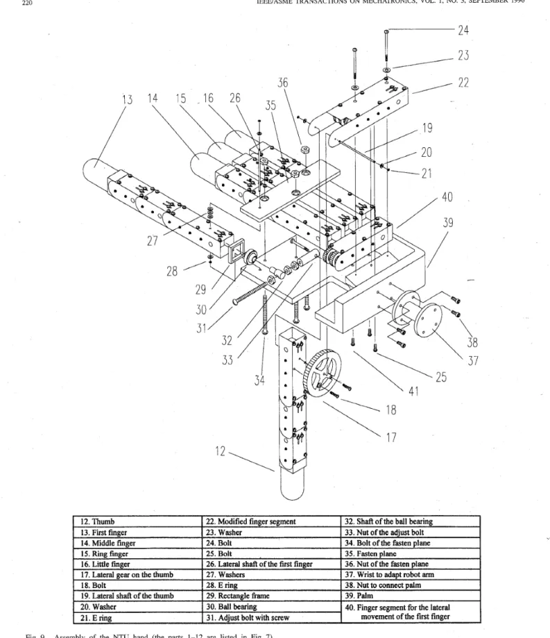
2) Auxiliary Device for the Lateral Joints: To ease the manufacture effort, the lateral rotation of the thumb and the first finger is achieved by adding an auxiliary device to a fundamental finger, and the mechanic power is provided by an additional finger segment. The auxiliary devices of the thumb and the first finger are shown in Fig. 9. In the design of the lateral joint of the thumb, a large gear is attached to the thumb and a modified finger segment is used to drive it. In the design of the lateral joint of the first finger, an adjustable linkage with a ball joint is employed to transfer the mechanic power: i.e., it converts the rotation of the gear into the linear motion. The thumb and the first finger, each with four DOF’s, provide approximate anthropomorphous motions similar to the human hand.
3) Palm and the Wrist: The palm serves as, a structural mounting base for the thumb, fingers and the wrist. The last three fingers are fixed on the palm by a board that arranges the fingers to cooperate with the thumb and the first finger. The upper space of the palm provides the location to install the controller and various electronic components [6]. The overall design scheme of the NTU hand is shown in Fig. 9. The wrist shown in the scheme is designed to connect the NTU hand to the robot arm PUMA 560. Once the design of the NTU hand is modified for rehabilitation, the wrist needs to be changed to adapt to the prosthetic patients.
B. Spec$cation of the Prototype ,
Specification of the three joints of each finger are all the same. Since the lateral joints Cjoint 0) of the thumb and the first finger are performed by different auxiliary devices, specifications of these two joints are special. Specification of the NTU hand is listed in Table I. The prototype of the NTU hand is made of metal. Its weight can be reduced when other materials are used. The rated weight of the object to be manipulated dynamically is determined by dexterous operation while the object is operated by fingertips of the hand. The rated weight of the object to be grasped statically is determined by power grasp operation while the object is grasped by the fingertips and the inner links of the fingers and the palm of the hand.
220
17
Fig. 9. Assembly of the NTU hand (the parts 1-12 are listed in Fig 7) C. Relationship with the Control Issue
Installation of Control System: The back space of the NTU hand is preserved for the electrical hardware of the control system, as shown in the upper space of Fig. 9. There are many
electrical wires for each finger segment and tactile sensors. If a remote controller is used, there will be too many wires between the hand and the controller. Based on this fact, a specifically designed controller is needed to fit into the preserved space
LIN AND HUANG: INTEGRATING FUZZY CONTROL OF THE D E X n R O U S NTU HAND
TABLE I
SPECIFICATION OF THE PROTOTYPE OF THE NTU HAND Joint 0 of Joint 0 of Joint 1 of
the thumb the fust fmger each fmger
I
maximum angular
velocity 0.21 rad/s
I
0.39 rads 1.05 radsI I I
I
I
I
bandwidthI
0.15 HzI
0.31 HzI
0.50 Hz torque output 3661.9 g-cm 1971.8 g-cm 1350.1 g-cmThe weight of each fmger
The total weight of the NTU-Hand
I
The rated weight of the object to be manipulatedI
The rated weight of the object to be graspedI
The maximum linear velocity of fmgertipThe current consumption of the whole hand mechanism
2.85 Hz 3.50 Hz
1569.0 g
877.1 m d s OA - 8.5A
221
and connect with the electrical components of the NTU hand. It also needs to dissipate the heat for pQwer amplifiers. The shell of the NTU hand can be used as heat sink.
Tactile Sensors: One of the important sensing functions of the human hand is its tactility. A multifingered hand needs tactile sensors for detecting contact force. Based on the consideration of contact possibility, cost, and practical implementation, the tactile sensors are attached to the finger tips, the inner sides of finger segments and the palm, as shown in Figs. 4 and 5. The palm and each finger of the NTU hand are equipped with tactile sensors to detect grasping force. Each tactile sensor is calibrated to cooperate with the hardware of the control.
The tactile sensor we used is called FSR (Force Sensing Resistor), shown in Fig. 8 [4]. It acts as a variable resistor. Since the characteristics of FSR are nonlinear, as shown in Fig. 8, the FSR can not be used directly. It must be processed to transfer into the linear scale by a digital processor. This value is then used for sensor integration.
Adaptation for Control: Due to the mechanism configura- tion of the NTU hand, the control of the finger can be treated as a linked robot. In other words, the dynamics analysis and control techniques used for robots can be applied to the fingered hand. Hence, the control of the NTU hand can be treated as the problem of control and sensor integration with finger joint and tactility.
111. Fuzzy CONTROL SCHEME
The control scheme of the NTU hand can be divided into three major parts. The first part is the knowledge bases
of grasping experiences, which is the source of the control strategy. The second part is the MIMO fuzzy controller, which performs the fuzzy logic inference from the knowledge bases to exert the grasp control plus sensor fusion of finger position and force. The third part is the self-organized mechanism to improve performance, which modifies the knowledge bases from the relationship of the inputs and outputs.
A. Knowledge Bases of the Fuzzy Control
By observing the grasping of the human hand, the initial stage is to make it touch the object. Once the object is touched, the fingers exert force to hold the object. In the meantime, the posture of the hand is adjusted to meet the desired task. The grasping process is shown in Fig. 10. Since the human being is an excellent expert in grasping, the amount of force applied by the fingers and the posture change is smoothly coordinated. However, the knowledge of experienced grasping is important for the control of the NTU hand.
In this paper, the fuzzy control is introduced to embed the linguistic experience of human. In the knowledge bases of the system, some rules and membership functions are designed to accommodate the backlash and friction of gear transmission. B. MIMO Fuzzy Logic Controller
Since the mechanism of the NTU hand is composed of the fundamental fingers, the proposed fuzzy logic controller is also applied to the finger. The fuzzy controller of the control system is shown in Fig. 11. The controller for each finger contains six inputs and three outputs. The six inputs consist of three joint
222 IEEEIASME TRANSACTIONS ON MECHATRONICS, VOL. 1, NO. 3, SEPTEMBER 1996
Enorsofthe joints and
tactile Fuzzifier sensing
(1) The posture and the
contact force are set posture and assigned for grasping force command and the hand is opened
MIMO inference engine
,
-
51 - j ; - jl-
5 2 j ; - j 2 5 4f ;
-fl
x5f ;
- f 2 -x6-
-f3*
- f 3 - 5 3 - - j: - j 3 and - yc =[i]
=[$]
(4) (2) Move the fingers to thespecific posture slowly -
I I
force error is large, posture error is large
No
> (4) return to initial stage
- force error is large
force error
.
is small1
YESFig. 10. Grasping experience of human being.
positions and three tactile forces, while the three outputs are from analog controllers.
The fuzzy rule bases consist of a collection of fuzzy IF- THEN rules in the form
RLINo: IF 5 1 is I$ and.
. .
and z, is FL THEN (1) where F," and Gt are fuzzy sets in U,c
R and V ,c
R,respectively, and g = (XI,
. . .
,z,) E Ul x. . .
x U, andy = ( y ~ ,
. . .
,
ym) E VI x . . . x V, are linguistic variables. Let be the number of fuzzy rules (i.e., 1 = 1 , 2 , .. .
, p ) and g and y be the input and output of the system. The fuzzy rules can be organized as [91y1 is GI and.
. .
and ym is GAThis shows that the general rule structure of a MIMO fuzzy system can therefore be represented by a collection of multiple-input-single-output (MISO) fuzzy system.
According to ( 2 ) , the divided MISO fuzzy system can be used for the inference of control. The fuzzy logic systems with center average defuzzifier, product-inference rule and singleton fuzzifier are of the following form [21]
r l
workstation KnowledgeU
---
Fig. 11. Fuzzy controller for one finger.
where y i is the output of the MISO fuzzy control and pF; denotes the triangular membership function for the fuzzy set
e.
The<;
is the center of the fuzzy set Gk; i.e., the point in V k at which the triangular membership function pG; of GL achieves its maximum value.The input g of the fuzzy logic controller is the error between the desired finger joint positiodforce and actual positiodforce. The output yc of the controller is the difference between the command o f th e analog inner loop controller and actual joint force/torque. Namely,
where j: is the desired joint command; f,* is the desired force command; j , and fi are the feedback of the joint and tactile sensors. The control effort 7," is the joint torque of the i-th joint. Since 7," E
ICi(c,
- j , ) , the input e, of the inner loopanalog PD controller is obtained from the proportional gain IC;. The performance of the fuzzy system is aimed at the grasping purpose. It can be adaptive by the self-organized mechanism which shown in next section.
The task of sensor integration is performed by (3) and (4) and cooperate with the knowledge base as (1). Since there are many computations in table lookup, multiplication and summation, a DSP chip is introduced to perform the fuzzy inference. The implementation of the fuzzy controller means direct coding in assembly language and takes advantage of the features of the DSP to speed up the whole system. In order to simplify the design of the whole control system, the control
of the additional lateral joints of the thumb and the first finger is not included in the fuzzy control. They are only position control in this system. The DSP-based fuzzy control system will be discussed in next section.
C. Self-organized Mechanism
The adaptive function of the fuzzy system is performed by the proposed self-organized mechanism. The self-organized mechanism is designed to improve the grasping performance to meet the requirements. Namely, it is aimed to improve the performance of force control and transition phenomenon upon
LIN AND HUANG: INTEGRATING FUZZY CONTROL OF THE DEXTEROUS NTU HAND I
:
I 223 Analog Controller I IAnalog Controller Analog Controller Analog Controller
with Power Driver withPowerDriver withPowerDriver with Power Driver
:
I
Host Computer
SUN Workstation
High level computation
I
MODEM or Direct Connect
4
Power Suppply
All in
NTU Hand
Fig. 12. Architecture of the control system
Fig. 13. Control system of the NTU hand.
contacting an object. The self-organized mechanism deals with the sensor data (the input) and the analog commands (the output) of the finger motor control. Notice that the output of the fuzzy system in (1) is also the analog commands of the finger motor control.
Each sampling period contains six sensor data and three analog commands of the inner control loop for each finger. Denote the sensor data (three joint positions and three tactile force data) as :,, and denote the three commands to the inner control loop as
c,.
(c,,g,) forms a set of input-output224 IEEEIP
X s =
k]
= -iSME TRANSACTIONS ON MECHATRONICS, VOL. 1, 40. 3, SEPTEMBER 1996
- j s 1 - j s 2 j s 3
fsl
f s 2 -fs3 -Fig. 14. Analog controller with power amplifier.
and
Ys1
Y,
= Ys2-
iys3
The self-organized nechanism learns 1 : relation between y s k
and f s k for f s k
>
0 ( k = 1 , 2 , 3 ) . The learning algorithm isbased on a fuzzy approximation. The membership function of the fuzzy approximation is the same as the fuzzy controller, and the learning algorithm is given by
C L
7:(
rIE1
l-LG+))C L
(
rIL
PGf ( Y s z ) )'
f L k ( 9 ) =for fsk
>
0, k = 1 , 2 , 3 . (6)The learning rule for the maximum firing strength of the rule with respect to the k-th joint is proposed as
(7)
f s k
T&(n
+
1) = T $ ( n ) T ,f S k
n = 0,1,2,. . .
where
flk
is the output of the MIS0 fuzzy approximation andpG; denotes the triangular membership function of the fuzzy set G i . 77; is the center of the fuzzy set
HL
in w k 3 R; i.e., the point in W k at which the triangular membership functionp H ; of H i achieves its maximum value. In (7), 7; (0) must not be zero initially and
flk
must be positive due to the fact that the tactile sensing is always positive. All the training pairs are used in the fuzzy approximation of (6) and (7,). The algorithm keeps learning until the errors are small enough.Once the relation between ys and fs is learned by learning
algorithm, one value of the parameter 7: for each rule 1 and each joint
IC
can be obtained. Therefore, there are 1 x k values of 7: to be stored and these values result in many fuzzy sets Hk in the universe of discourse. Since the number of the fuzzy sets F," in (1)-(3) is limited for improving the efficiency of inference, the learning result can not be directly used. In order to apply the result of the fuzzy approximation to control strategy, the number of fuzzy sets Hk should be reduced toL
(b)
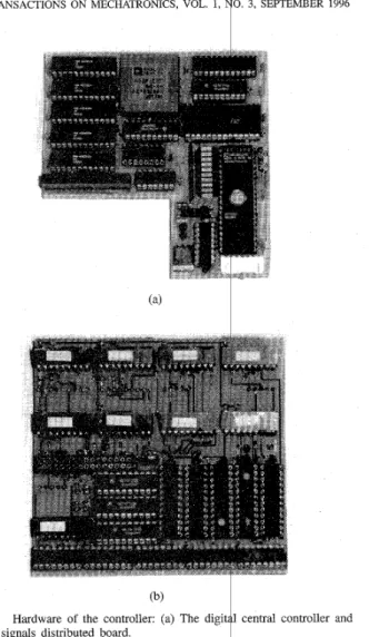
Fig. 15.
(b) the signals distributed board
Hardware of the controller: (a) The digit central controller and
the limited number of the fuzzy sets F,". It can be achieved by classifying the fuzzy sets Hk into the number of the fuzzy sets F,". In other words, the downsizing of fuzzy sets
HL
shouldbe performed. I
Since the computations of the above /learning algorithm are huge and the task can be separated from the control, a fuzzy development environment is construdted to distribute the computation load. The computation of fuziy approximation is separated from control and performed by a workstation in the proposed control architecture. It will be ,shown in the next
section. ,
A. Specijically Designed Control System
Control System Architecture: There are 17 signal groups in the control system of the NTU hand. ~ Each signal group
contains three sets of wire connection. The first wire set deals with the position sensors. The second sed is the tactile data. The third set is the power lines of motors, which is the power
LIN AND HUANG: INTEGRATING FUZZY CONTROL OF THE DEXTEROUS NTU HAND 225 1.15 . 30 ‘15 0 - 8 60 ~ 45 - . i k 3 0 -8 15 - 1 1/50 sec 180 (a)
H
8 -10 60 Joint 02 5 -. 0 - 0 45 - 45 -&
30 . 7 8 30 . ia 4 8 15 ~ b - 8 0 0 1 1/50 sec 180 1 1/50 sec 180 (b) (C)&
30 - 15 - 01 1/50 sec 180 1 1/50 sec 180 1 1/50 sec 180
(4 ( e ) (f)
(4 ( e ) (f)
The first problem encountered is space limitation. From the mechanical design of the NTU hand, the dimension of the circuit board must be within ten square centimeters. It is impossible to implement the controller and power drivers in one board. Therefore, two cascade boards and power modules are designed to meet space limitation. One board is the digital central controller, the other is for the distribution of analog signals and connection to power modules.
Since there are 17 joints to be controlled simultaneously, the arrangement of the computation load is very important. The overall computation is divided into two parts: high level and low level. The high level computation is performed by a SUN workstation. It uses a three-dimensional graphic front- end to monitor the posture of the NTU hand while the position
changes. It primarily performs the coordination planning of dexterous manipulation, high level computation of control, and the proposed fuzzy approximation. The low level computation is a hand controller which combines a single DSP and analog controllers to control 17 finger joints of the NTU hand. The architecture of the hand control system is shown in Fig. 12. It is proposed to meet the fast computation and the space limitation of the NTU hand. The details of the control system are shown in Fig. 13. Clearly, the control system consists of a host computer, digital central controller and several analog control modules.
The digital central controller contains an ADSP 2101-44 DSP chip and peripheral devices. It performs the fuzzy control in terms of sensor data and commands from the host computer,
IEEE/ASME TRANSACTIONS ON MECHATRONICS, VOL. 1, NO. 3, SEPTEMBER 1996 226 60 45 f 30 15 0 8 60 45
&
30 8 15 0 Joint 23 60 Joint 21 Joint 22 60 45 45k
30 -8f
30 -8 15 15 0 0I 1/50 sec 180 1 1/50 sec 180 1 1/50 sec 180
(i) (k) (1) Joint 33 60 Joint 31 Joint 32 60 45 45
&
30 30 15 15 0 0 8 41 1/50 sec 180 1 1/50 sec 180 1 1/50 sec 180
(m) (n) ( 0 ) Joint 43 60 Joint 41 Joint 42 60 60 45 45 45 30
h
30k
30 15 15 15 0 0 0 448
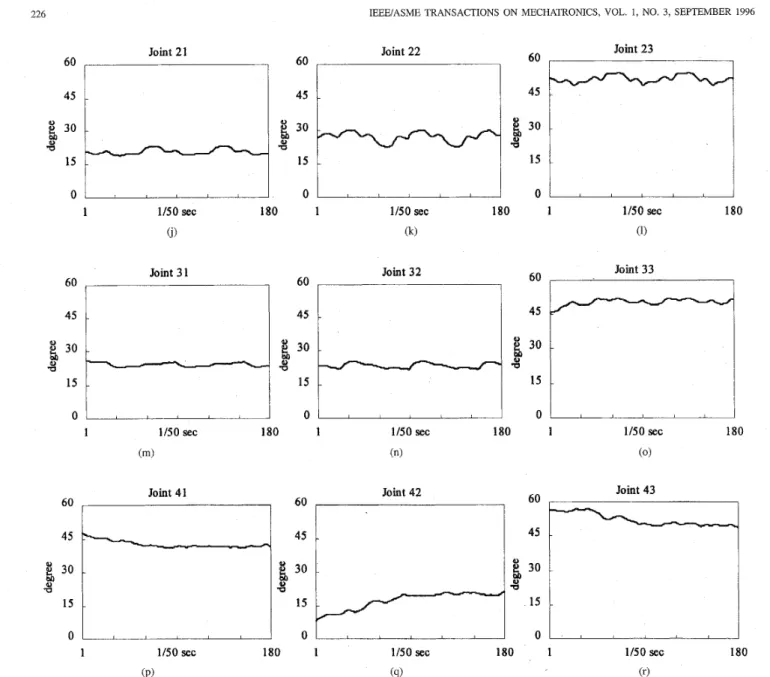
B 180 1/50 sec 1 1/50 sec 180 1 1/50 sec 180 1 (PI (4) (r)Fig. 16. (Continued.) Trajectories of the disc object and fingers while grasping. (The first diagram (a) is the desired orientation in the y axis. The grasped object is also shown in Fig. 21. The others diagrams are the joint trajectories of the multifingered robot hand): (i) joint trajectory of finger 2, joint 1, (k) joint trajectory of finger 2, joint 2, (1) joint trajectory of finger 2, joint 3, (m) joint trajectory of finger 3, joint 1, (n) joint trajectory of finger 3, joint 2, ( 0 ) joint
trajectory of finger 3, joint 3, (p) joint trajectory of finger 4, joint 1, (4) joint trajectory of finger 4, joint 2, and (r) joint trajectory of finger 4, joint 3.
then distributes commands to each analog control module, and sends information to the host workstation as well. The analog controller is a PD (proportional plus derivative) controller with a power amplifier. It performs the joint space control for each finger joint and shares the computation load.
1 ) Communication Microprocessor: The NTU hand is de- signed to communicate with a host workstation, as shown in Figs. 12 and 13. A graphic font-end host computer is used to perform the coordination planning of dexterous manipulation. The signal between the host computer and the digital central computer is transmitted through RS232 with 19 200 baud rate. The serial connection is an easy way to achieve bilateral remote operation. It can be replaced by telephone line with
MODEM.
By introducing the Intel 87C5 1 microprocessor to perform the communication task, the computation load of the digital central controller is reduced. The information sending to or receiving from the host workstation should be stored into a central memory which is between the microprocessor and the digital central controller. According to a specific logic, the content of the memory is shared by two processors.
2) Analog Control Module: There are 17 DOF’s in the con- troller. The computation load will be too heavy if the control laws of all joints are performed by the digital controller. The hand control system based on the combination of digital and analog controllers, as shown in Fig. 13, is constructed to per- form the fast computation. The inner loop analog controllers contribute more control effort than the digital controllers in
LIN AND HUANG: INTEGRATING FUZZY CONTROL OF THE DEXTEROUS NTU HAND 400E-01
-
300E-01-
h2
2.OOE-01-
v * .- E 100E-01-
000Effl0 ~ ~ 227 -j 11 * (desired) m-
.
rn.
j l l (simulation) 2.3-
2 1-
1 9-
1 7-
h 8 1.5 - i&
1 3 - e Le I ] - , 0 9 Time (OSseddiv)Fig. 17. Simulation of joint control (finger 1, joint 1).
-fl3* (desired)
-
. .
. .
f13 (simulation).\
..,..
* -*....
.
...
..-*.-*..... ._..
.
.___...
U-:
0.71
0.3 0.2 -jIl* (desired)-. .
m . j l l (actual) 0 Time (0.5seddiv)Fig. 18. Experiment of joint control (finger 1, joint 1).
the joint space control. Hence, the sampling rate of the digital controllers can be reduced by introducing the analog loop.
The analog controller is a PD controller with a power amplifier. It performs the joint space control for each finger joint. Due to space limitation, two analog controllers are placed in one PCB board, as shown in Fig. 14. This PCB board is then connected to the analog signal distribution board, as shown in Fig. 15(b). Because the control module is the top layer of the control system, the heat sinks equipped on the electric power devices of the control module can be easily installed at the place near the cover of the hand.
3) Digital Central Controller: The digital central controller contains an ADSP 2101-44 DSP chip [2] with peripherals, which include digital to analog converters, analog to digi- tal converters and multiplexers. The controller switches the multiplexers and gets the sensor data from the analog to digital converters. Once the sensor data are obtained, the controller computes the control law in terms of sensor data and commands from the host computer, then distributes commands
to each analog control module, and sends information to the host workstation while the posture change.
The control law of the digital controller can be downloaded from communication connection, or can just run the basic control law from the boot device. The PCB boards of the control system are shown in Fig. 15(a) and (b). The controller board shown in Fig. 15(a) is the digital controller with analog
0.7
1:
0.5
4
Time (0.5seddiv)
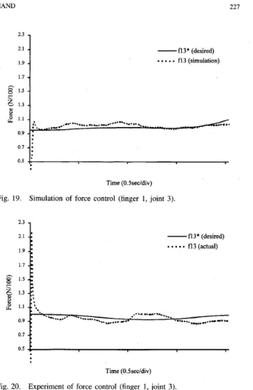
Fig. 19. Simulation of force control (finger 1, joint 3).
2.3 1.7 -fl3* (desired)
. .
- - -
f13 (actual) Time (O.Ssec/div) Fig. 20.to digital converters and communication microprocessor. The analog signal contribution board shown in Fig. 15(b) contains the digital to analog converters, multiplexers and data latches. It provides connectors to connect the analog control modules and data transfer to the digital processor.
Since there exists backlash in the gear driven mechanism, the dynamic behavior of the NTU hand suffers from this nonlinearity. However, the grasp operation is unilateral. There- fore, the backlash problem will not occur when the object is held up. Moreover, the fuzzy controller will compensate the nonlinearity to certain extent.
The feedback data of NTU hand contains the finger joint and tactility. The joint position can be directly fedback from the potentiometer, as the part 11 of the Fig. 7. The tactility feedback can not be directly used since the tactility data is nonlinear. The data must be pre-processed and converted into linear data for feedback. This job is done by the digital controller. It is clear from Fig. 13 that the tactile sensing signals are directly fedback to the DSP through multiplexers. The central digital controller performs the outer-loop control as we proposed.
B. DSP-Based Fuzzy Control
The control system of the NTU hand provides a develop- ment environment for fuzzy control. Due to the use of specially designed communication modules between the workstation
228 IEEEIASME TRANSACTIONS ON MECHATRONICS, VOL. 1, NO. 3, SEPTEMBER 1996
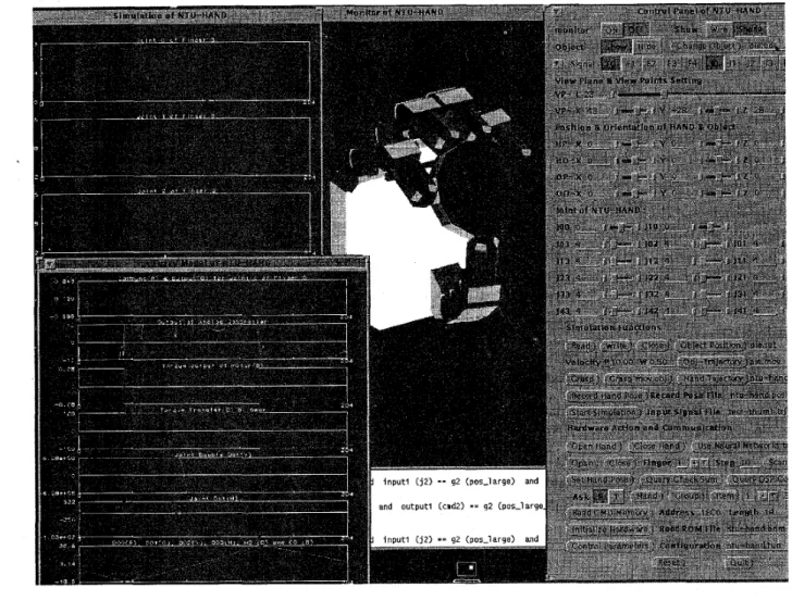
Fig. 21. MMI of the fuzzy control system.
and the digital central controller, the knowledge bases of the fuzzy control can be initially set from the simulation result in the workstation and modified during the operation. During the run time, the self-organized mechanism still works in the workstation to monitor the performance of the whole hand at each sampling interval. The user can save the improved knowl- edge bases for further use or down load into the controller immediately.
The whole finger hand is controlled by the MIMO fuzzy controller. Each finger of the NTU hand can be treated as a linked robot. Since there are five fingers with 17 joints to be controlled simultaneously, there will be five fuzzy controllers
to be computed in the same time in order to control the NTU hand. The computation load should be shared by another device other than the central controller to perform low level control. By introducing the inner loop analog PD control, the sampling rate of the DSP fuzzy controller is reduced by an order.
In order to get efficient inference of the fuzzy control, the assembly language is used to code DSP programs. From the technical reference of the DSP, the computation can be speeded up by using convolution calculation (summation of multiplication). That is why the product-inference is used
in (3). In the DSP fuzzy control, up to 4 x lo5 rules can be inferred in one second. The major limitation of speed is the conversion time of the analog to digital converter. The sampling period of each joint control is 10 ms in the
DSP controller. However, parts of the computation are spent on the defuzzification process. A more efficient method of defuzzification will speed up the computation.
C. Results of Simulation and Experiment
Suppose that the object is initially grasped by the mul- tifingered robot hand as Fig. 21. The desired trajectory is
given as Fig. 16(a). In other words, the object is manipulated rotationally in y axis and kept stationary in other axes. As the object changes to a new orientatiodposition, the new positions of contact points are passed to the inverse kinematics of the multifingered hand and a corresponding hand posture is found. Fig. 16(b)-(r) show the trajectories of the NTU hand.
The results of the simulation and experiments of the finger control are shown in Figs. 1 7 3 0 . In general, the difference between the simulation and experiment in the joint control case is larger than that in the force control case. The reason is that the self-organized mechanisms in the development environment of the NTU hand only deal with the relation
LIN AND HUANG: INTEGRATING FUZZY CONTROL OF THE DEXTEROUS NTU HAND 229
of position and force. The MMI of the fuzzy development environment, as shown in Fig. 21, displays all control signals during simulation and experiments. The parameters of the controller can be adjusted from the MMI control panel during operations. The three dimensional graphics are used to show the hand posture, and the gray color is used to indicate the intensity of the tactile force on the NTU hand.
V. CONCLUSION
[ l 11 E. H. Mamdami and S. Assilian, “An experiment in linguistic synpaper with a fuzzy logic controller,” Int. J. Man-Machine Studies, vol. 8, pp. 249-291, 1976.
[12] X. Markenscoff, L. Ni, and C. H. Papadimitriou, “The geometry of
grasping,” Int. J. Robot. Res., vol. 9, no. 1, pp. 61-74, 1990.
[13] B. Mirtich and J. Canny, “Easily computable optimum grasps in 2-D and 3-D,” IEEE Int. Con$ on Robotics and Automation, 1994, pp. 739-747.
[14] D. Nauck and R. Kruse, “A fuzzy neural network learning fuzzy control rules and membership functions by fuzzy error backpropagation,” in
Proc. IEEE Int. Con$ on Neural Networks, 1993, pp. 1022-1027.
[15] M. H. Raibert and J. J. Craig, “Hybrid positiodforce control of ma- nipulators,” ASME J. Llyn. Syst. Meas. Contr., vol. 102, pp. 126-133,
June 1981.
1161 T. H. Sueeter. “Control of the Utah/MIT Dextrous hand: Hardware and
~-
software hierarchy,” J. Robot. Syst., vol. 7, no. 5, pp. 759-790, 1990. [17] T. H. Speeter, “Primitive based control of the U W I T Dextrous
Hand,” IEEE Int. Conf: on Robotics and Automation, 1991, QQ. 886877.
The robot hand’ the NTu hand’ with l7
degrees of freedom has been designed and fabricated to achieve dexterous manipulation. To control the NTU five-
finger robot an integrated fuzzy system with
sensor integration is developed in this paper. Since there are so
[18] S. A. Stansfield, “Gowledge-based robotic gasping,” IEL% Int. Con$ on Robotics and Automation, 1990, pp. 1270-1275.
[19] R. Tomovic, G. A. Bekey, and W. J. Karplus, “A strategy for grasp svnuauer with multifingered robot hand,” IEEE Int. Con6 on Robotics
- _ _
many joints to be controlled simultaneously and involve hand dynamics of movement and force, the adaptive fuzzy control is implemented to take the features of the DSP, and a hierarchical
ana! Automation, 1987,-pp. 83-89.
[20] M. Umetsu and K. Oniki, “Compliant motion control of arm-hand sys-
tem,’’ JSME Int. Con$ on Advanced Mechatronics, 1993, pp. 429432.
[21] L. X. Wang, Adaptive Fuuy Systems and Control: Design and Stability Analysis. Englewood Cliffs, NJ: Prentice-Hall, 1994.
[22] L. A. Zadeh, “Fuzzy sets,” Inform. Contr., vol. 8, pp. 338-353, 1965. architecture Of the system is proposed to mange the
computation load. A fuzzy development environment is also
built to show the signals of the simulation and experiment,
and the three dimensional graphics are used to show the posture and status of the NTU hand. Furthermore, according to communication functions of the control system, the knowledge bases can be loaded for high level computation and modified during run time.
REFERENCES
G. A. Bekey, H. Liu, R. Tomovic, and W. J. Karplus, “Knowledge-based
control of grasping in robot hands using heuristics from human motor skills,” IEEE Trans. Robot. Automat., vol. 9, no. 6, pp. 709-722, 1988.
DSP Division, ADSP-2101/2102 User’s Manual, Analog Devices Inc.,
U S A . , 1991.
I. Fowler, Human Anatomy. Belmont, CA: Wadsworth, 1984, p. 155.
FSR Technical SpeciJications, Interlink Electronics Inc., Carpinteria, CA,
1989.
N. Hogan, “Stable execution of contact tasks using impedance control,”
IEEE Int. Con$ on Robotics and Automation, 1987, pp. 1047-1054.
H. P. Huang and L. R. Lm, “Development of a prosthetic hand with
multifingers,” NSC Rep., NSC 84-2212-E002-032.
S. C. Jacobsen, J. E. Wood, D. F. Knutti, and K. B. Biggers, “The UTAWMIT dextrous hand: Work in progress,” - - Int. J. Robot. Res., vol.
3, no. 4, pp. 21-50, 1984.
J. S. Jane, “Self-learning fuzzy controllers based on temporal back - . propagati&,” IEEE Trans. Neural Networks, vol. 3, pp. 723-741, 1992.
C. F. Lin, Advanced Control System Design. Englewood Cliffs, NJ:
Prentice-Hall, 1994, pp. 441446.
L. R. Lin and H. P. Huang, “Mechanism design of a new multifingered robot hand,” IEEE Int. Con$ on Robotics and Automation, 1996, pp.
1471-1476.
Li-Ren Lin received the B.S. degree in mechanical engineering from the National Taiwan Institute of Technology, R.O.C., in 1992, and the Ph.D. degree in mechanical engineering from National Taiwan University in 1996.
His research interests include mechanism design, three dimensional graphic simulation and controller design of mechatronic system, especially with many degrees of freedom. His current research inter- ests include real-time network communication, shop floor control, control and emulation in IC manufac- turing automation.
Han-Pang Huang (S’83-M’86) graduated from Na- tional Taipei Institute of Technology, Tapei, Tai- wan, in 1977, and received the M.S. and Ph.D. degrees in electrical engineering from The Univer- sity of Michigan, Ann Arbor, in 1982 and 1986, respectively.
Since 1986, he has been with National Taiwan University, where he is currently a Professor in the Department of Mechanical Engineering. His research interests include machine intelligence, shop floor control, robotics, and nonlinear systems. Dr. Huang is editor of the Journal of Chinese Fuzzy System Association,
the Chairman of the IEEE Robotics and Automation Taipei Chapter, and is the director of the Manufacturing Automation Technology Research Center (MATRC). He is a member of Tau Beta Pi.
![Fig. 6. Human hand [3].](https://thumb-ap.123doks.com/thumbv2/9libinfo/8866187.246532/3.921.466.850.116.615/fig-human-hand.webp)