行政院國家科學委員會專題研究計畫 成果報告
子計劃四:All-IP 網路 End-to-End 品質管理之研究(I)
計畫類別: 整合型計畫
計畫編號:
NSC91-2219-E-004-005-執行期間: 91 年 08 月 01 日至 92 年 07 月 31 日
執行單位: 國立政治大學應用數學學系
計畫主持人: 陸行
計畫參與人員: 連耀南、張宏慶、蔡子傑
報告類型: 完整報告
處理方式: 本計畫可公開查詢
中
華
民
國 92 年 9 月 23 日
行政院國家科學委員會補助專題研究計畫成果
報告
※※※※※※※※※※※※※※※※※※※※※※※
※※※※
※
※
All-IP 網路上以預算為基礎之品質管理研究
※
※
子計劃四:All-IP 網路 End-to-End 品質管理之研究
(I)
※
※
※
※※※※※※※※※※※※※※※※※※※※※※※
※※※
計畫類別:□個別型計畫
■整合型計畫
計畫編號:NSC 91-2219-E-004-005-
執行期間:
91 年 8 月
1 日至
92 年 7 月 31
日
計畫主持人:陸行
共同主持人:
計畫參與人員:
本成果報告包括以下應繳交之附件:
□赴國外出差或研習心得報告一份
□赴大陸地區出差或研習心得報告一份
□出席國際學術會議心得報告及發表之論文各一份
□國際合作研究計畫國外研究報告書一份
執行單位:國立政治大學應用數學系
中
華
民
國 九十二 年
七 月
三十一 日
行政院國家科學委員會專題研究計畫成果報告
All-IP 網路上以預算為基礎之品質管理研究
子計劃四:All-IP 網路 End-to-End 品質管理之研究(I)
計畫編號:NSC 91-2219-E-004-005-
執行期限:91 年 8 月 1 日至 92 年 7 月 31 日
主持人:陸行 國立政治大學應用數學系
中文摘要
假設核心網路及接取網路均能提供具服務品質保證之乘載服務,本研究之目的在全 IP 網路提供具適應性的端對端服務品質保證管理機制。利用事前規劃滿足封包服務品質 需求的 End-to-End path,並於實際傳遞封包時建立路徑並保留所需之資源,以提供 End-to-End 服務品質保證。而且,利用預算為基礎之服務品質管理,以簡化管理、追 求效率,不增加管理複雜度為設計原則。採用作業研究與最佳化,運用整數規劃及目標 規劃,以事前規劃(off-line planning)的方式規劃最佳資源分配。關鍵詞:端對端服務品質保證、作業研究、最佳化
Abstr act
An important problem that the network service providers face is how to maximize the utilization efficiency of its physical network by admitting as many customers as possible while satisfying every specific QoS requirements. In this paper, we state briefly an approach for the problem of QoS budget allocation which is deliberated in optimization for increasing resource usage efficiency. The proposed framework with simulation study demonstrates that it can indeed substantially increase the total number of network paths under constraints of end-to-end QoS requirements.
Keywords:
QoS Protocols and Provisioning, Next Generation Internet Protocols, QoS Routing.1.
Intr oduction
As telecommunications networks developed towards 3G networks, All-IP Networks integrate Circuit Switching and Packet Switching networks [1-2] and thereby provide both real-time services and data services with IP-packets.
Topographically, communication networks are mostly connected in networks provided by a group of telecommunication companies. All-IP Networks are composed of Stub Networks
and Core Networks [3]. Stub Networks can only provide communications within the same cluster of end users. If end-users need to make long-distance calls, they would probably mark out a number of Core Networks among different operators.
Operators have own Core Networks to connect Stub Networks. Core networks hook up the backbone by using domain inter-connection links. When users need services from different telecommunications companies, they send the packets to the backbone via a local Stub Network, and the backbone forwards the packets to a remote Stub Network. So, packets are delivered to the destination host in provision of network services. Refer to Figure 1. Core Network Core Network Stub Network WLAN Stub Network UMTS Other PLMN Campus Network Stub Network GPRS BRAIN Core Network IG IG IG BG BG BG BG BG BG AG AG AG AG AG AG AG AG AG BG AG IG BG Inter-Domain Gateway Border Gateway Access Gateway
Stub Network Figure 1. All-IP Network architecture
We break All-IP Networks from hierarchical relations into two subcategories, namely, a backbone and Stub Networks. A backbone is connected by Core Networks. Edge routers of backbones are called Border Gateways (BG). The Border Gateway is an Ingress/Egress router of the backbone. Stub Networks are networks that provide end users’ services directly. They might be public landing mobile networks, e.g., UMTS, GPRS, 802.11, fixed networks or other type of networks. Stub Networks provide services for end users by Network Access Servers (NAS).
In this paper, we assume all the surrounding Stub Networks and Core Networks associated with the backbone belong to the same group. The end-to-end QoS controller in QoS coordination layer has the capability of global resource planning. It suggests that an end-to-end QoS controller will plan all resource provisions according to the traffic demands, and all the resource allocation policy will be in accord with the planning. The paper is organized as follows. The next section introduces the QDF and budget-based management. Afterwards, we propose a system architecture for end-to-end QoS provisioning, and finally the simulation study is p
resented.
2.
QDF and Ser vice Class Mapping
Based on the classes of UMTS (Universal Mobile Telecommunication System) [4], Quality parameters are known as delay time, jitter (delay variation) and packet loss. UMTS also separates users’ needs of quality parameters into Conversational, Streaming, Interactive and Background. The four service classes distinguish different quality levels. For example, Conversational classes can tolerance a considerable amount of packet loss, but a little delay; Background bears a totally opposite behavior.
In this paper, we present an implementation scheme regarding Quality Deployment applied to communication network management. A Quality Deployment Function (QDF)
reflects the value that is reciprocal to the quality level. The smaller value shows the better quality level. Contrarily, the larger value of QDF shows the lower quality level. QDF can be evaluated from delay time, jitter or packet loss. In sequel, we use the QDF as the single index that may be delay time, jitter or packet loss. In general, QDF may be defined in accord to different operators’ need.
Taking QDF for the index of the quality level into account, we need to map the users’ need to QDF.
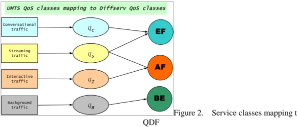
UMTS QoS classes mapping to Diffserv QoS classes
Conversational traffic Background traffic Interactive traffic Streaming traffic EF AF BE qc qs qI qB
Figure 2. Service classes mapping to QDF
Consider a case of mapping in UMTS. In Figure 2, the squares denote the service classes, the ellipses for different QDFs. The circles denote the QoS management technologies of the network layer. For example, taking the value of QDF of Conversational class qc, it means the quality level of Conversational class, and the EF class of DiffServ will execute the QoS policy for such a QDF. Based on QDF, we can make an arrangement to balance the resources that satisfyqcfor traffic demands of this class.
3.
Budget-Based Management
In a communication network, an end-to-end path might stride across different operators’ network domain. According to the service level that an end-to-end path carries the path has to give a corresponding quality level guarantee. For example, an end-to-end path which carries Conversational class services has to offer the QDF guarantee, qc. Likewise, an
end-to-end path has to offer qs guarantee whenever it carries a Streaming class.
In other words, we consider the QDF mapped from service classes as an
end-to-end QDF budget. An end-to-end path that does not exceed the QDF budget
requirement is said to be competent to carry such service classes. Budget-Based
management conceptually disperses QDF budget on the network domains which is
traversed by end-to-end paths. Whenever a QDF budget is placed on a network
domain, this network domain is responsible for offering a QDF satisfying QoS
requirements.
4.
System Architecture
4.1
Management System Hier archy
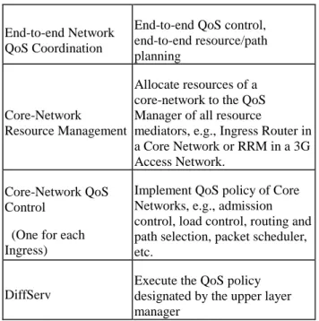
We propose a system architecture with components in “end-to-end Network QoS Coordination Layer” which is responsible for planning an end-to-end QoS.
End-to-end Network QoS Coordination
End-to-end QoS control, end-to-end resource/path planning
Core-Network Resource Management
Allocate resources of a core-network to the QoS Manager of all resource
mediators, e.g., Ingress Router in a Core Network or RRM in a 3G Access Network.
Core-Network QoS Control
(One for each Ingress)
Implement QoS policy of Core Networks, e.g., admission control, load control, routing and path selection, packet scheduler, etc.
DiffServ
Execute the QoS policy designated by the upper layer manager
Table 1. QoS Management Hierarchy
Components in the upper two layers in Table 1 plan Short paths and Long Paths for potential requests, which are described respectively in Table 2.
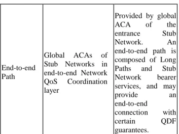
Planned Path Management
Component Function Short Path BBs and PPAs [5] of Core Networks in Core-Network Resource Management layer Computed and reserved by PPAs and BBs. A Short Path may cross a Core Network with certain QDF guarantees. Long Path LPPA* of backbone in end-to-end Network QoS Coordination layer Computed by LPPA. A Long Path is composed of Short Paths and may cross a backbone with certain QDF guarantees.
End-to-end Path Global ACAs of Stub Networks in end-to-end Network QoS Coordination layer Provided by global ACA of the entrance Stub Network. An end-to-end path is composed of Long Paths and Stub Network bearer services, and may provide an end-to-end
connection with certain QDF guarantees.
Table 2. Paths of different layers
4.2
Bearer Ser vice Architecture
According to classifications in Table 2, an end-to-end Service is composed of bearer services offered by different network domains. A basic long-distance call may traverse through more than two Core Networks. In figure 3, it shows the QDF budget for long-distance calls that pass through network domains.
TE Stub Network Core Network Stub Network Core Network TE End-to-End Service Stub Network Bearer Service Backbone Bearer Service (Long path) Core Network Bearer Service (Short path) Stub Network Bearer Service Domain Inter-Connection Link Core Network Bearer Service (Short path)
Figure 3. Bearer service architecture
5.
LPPA Optimization Model
5.1
An Optimization Model
MinimizePenalty made by unsatisfied traffic aggregates Subject to
Fixed resource (Limited Short Path bandwidth) Traffic aggregate QDF budget must be satisfied
Allocate resource to traffic aggregates
Trading off QDF with bandwidth in each Short Path
5.2
Exper iments
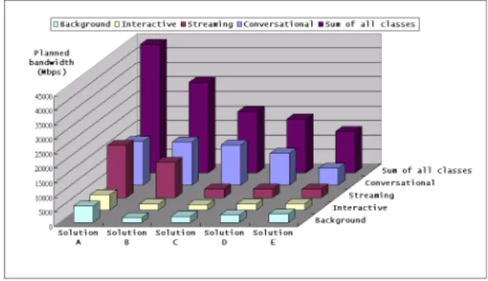
We set up an experimental model which constructs a network topology of twenty-four nodes. Ten of them are defined as Border Gateways. The bandwidth of each link is in range of 1200-2400 Mbps, and has different QDF guarantees. We conduct the LPPA optimization with ILOG [7].
Figure 3 shows the planned bandwidth of different classes. Solution A is an optimal solution and the others are feasible solutions. Given each class has different priorities, the premium classes will be considered first.
Figure 3. Planned bandwidth classes
Figure 4 shows the network utilization of each solution in six testing cases. Each testing case has the same amount of traffic demands, but we scatter the demand all over Border Gateways to get a balanced bandwidth requirement. It shows the optimal solution can utilize bandwidth usage up to about 70% in average.
6.
Conclusion
We focus on the differentiated service QoS model and present a possible approach to maximize the resource usage efficiency.
The proposed system architecture coping with end-to-end QoS by budget-based management are designed for long-term network resource provision, rather than for setting up individual network connections. We explore the design options implied by the architecture, including Quality Deployment Function, and LPPA Optimization Model. To make end-to-end QoS guarantees more efficiency concerning parameters of various traffic patterns, a model of forecasting link characteristics is one of future study that enhances this approach.
Refer ence
[1] 3rd Generation Partnership Project; " Architecture for an All IP network"; 3G TR 23.922 version 1.0.0
[2] Ivano Guardini, Paolo D’Urso, and Paolo Fasano, CSELT, "The Role of Internet Technology in Future Mobile Data Systems", IEEE Communications Magazine• November 2000
[3] Tetsuya Takine, Kyoto University Yuji Oie, Kyushu Institute of Technology Katsuyoshi Iida and Kenji Kawahara, Kyushu Institute of Technology, “Performance Evaluation of the Architecture for end-to-end Quality-of-Service Provisioning”, IEEE Communications Magazine• April 2000
[4] 3rd Generation Partnership Project; " QoS Concept and Architecture (Release 5)"; 3GPP TS 23.107 V5.3.0 (2002-01)
[5] Yao-Nan Lien, Tsung-Hsung Li, " Path planning in DiffServ Domain under budget-based control", Master Thesis, June 2003.
[6] Yao-Nan Lien, Ming-Chin Chen, " Budget-Based Admission Control on DiffServ Core Network", Master Thesis, June 2003.