876 IEEE TRANSACTIONS ON MAGNETICS, VOL. 43, NO. 2, FEBRUARY 2007
Effects of CrRu Underlayer and CrRu Capped Layer
on the Microstructure and Magnetic Properties
of FePt Films
S. C. Chen
1, P. C. Kuo
2, C. T. Lee
2, A. C. Sun
2, C. Y. Chou
2, and Y. H. Fang
2Department of Materials Engineering, MingChi University of Technology, Taipei 243, Taiwan, R.O.C. Institute of Materials Science and Engineering, and Center for Nanostorage Research, National Taiwan University,
Taipei 106, Taiwan, R.O.C.
The magnetic properties and microstructure of CrRu/FePt bilayer and CrRu/FePt/CrRu trilayer deposited by dc magnetron sput-tering on preheated natural-oxidized Si (100) wafer substrates were studied. It is found that both the in-plane coercivity(Hc ) and grain size of the FePt film increase with increasing the thickness of CrRu underlayer. TheHc value of the FePt film is further increased but the grain size is decreased as adding a CrRu capped layer on the FePt film. The granular 10FePt nanoparticles with in-plane co-ercivity of 2300 Oe and isolated uniform size of 6.61 nm are achieved from the CrRu(15 nm)/FePt(25 nm)/CrRu(4 nm) film deposited at a low substrate temperature of 350 C.
Index Terms—CrRu/FePt bilayer, CrRu/FePt/CrRu trilayer, in-plane coercivity, magnetron sputtering.
I. INTRODUCTION
T
HE FePt nanoparticles are a candidate material for next generation high-density magnetic recording media due to its excellent environmental stability and ultra high mag-netocrystalline anisotropy ( erg/cm ). However, FePt phase usually develops at a higher temperature around 600 C [1], [2], which results in the FePt nanoparticle agglom-erate and grain growth. Therefore, the ordering temperature of FePt phase must be reduced for preventing grain growth. In addition, the medium noise which caused by the magnetic grain interactions have to be also solved [3], [4].Previous studies had reported that the grain size and mag-netic grain interactions could be reduced by addition of various materials such as Si N [5] and AlN [6], but the addition of them would increase the ordering temperature of FePt. It has been known that the ordering temperature could be reduced by introducing a underlayer due to the lattice misfit between FePt film and underlayer [7], [8]. On the other hand, the depo-sition of capped layer on the FePt film could reduce exchange coupling between FePt magnetic grains [9], [10]. In this work, we use CrRu underlayer and capped layer to prepare CrRu/FePt bilayer and CrRu/FePt/CrRu trilayer films, and investigate the effects of CrRu underlayer and CrRu capped layer on the grain size, saturation magnetization and coercivity of the FePt film.
Digital Object Identifier 10.1109/TMAG.2006.888487
Color versions of one or more of the figures in this paper are available online at http://ieeexplore.org.
II. EXPERIMENT
The CrRu underlayer thickness in the range of 10–100 nm, the FePt magnetic layer of 25 nm, and 4 nm CrRu capped layer are all deposited by dc magnetron sput-tering at substrate temperature of 350 C. The base pressure in the sputtering chamber is better than Torr. The samples are cooled to room temperature under high vacuum in the sputtering chamber. The magnetic properties of the films are measured using a vibrating sample magnetometer (VSM) at room temperature. The microstructures of the films are investigated by a Philips Tecnai F30 field emission gun (FEG) transmission electron microscopy (TEM) and X-ray diffractometer (XRD) with Cu-K radiation. The compositions of the films are determined by EDS, and they are Fe Pt and Cr Ru for the FePt and CrRu films, respectively.
III. RESULTS ANDDISCUSSION
Fig. 1 shows the variations of and grain size of FePt films with varying CrRu underlayer thickness. Previous study [11] had reported that the in-plane coercivity of single layer FePt film with thickness below 30 nm only had several hundreds Oe after annealing at a low-temperature of 350 C. However, the value can be increased to 1700 Oe by introducing a 10 nm CrRu underlayer under the 25 nm FePt film which deposited at 350 C, as shown in Fig. 1. And is enhanced significantly to 4000 Oe as is increased to 50 nm. When the is further increased to 100 nm, the is further increased to 4280 Oe.
The value of the FePt film increases as increasing from 10 to 100 nm may be owing to the following reasons: 0018-9464/$25.00 © 2007 IEEE
CHEN et al.: EFFECTS OF CRRU UNDERLAYER AND CRRU CAPPED LAYER ON THE MICROSTRUCTURE AND MAGNETIC PROPERTIES OF FEPT FILMS 877
Fig. 1. The variations ofHc and grain size of the FePt film with CrRu un-derlayer thickness of the CrRu/FePt bilayer films which deposited at substrate temperature of 350 C.
(I) For randomly orientated noninteracting particles, the depen-dence of coercivity (Hc) on the particle size (D) can be described as [12]
(1) where Ms is the saturation magnetization. The minimal stable grain size (Dp) of FePt alloy is about 3 nm [13]. As shown in Fig. 1, the average grain size of FePt films increases from 6.3 to 21.3 nm as CrRu underlayer thickness increases from 10 to 100 nm. According to above equation, the increase in particle size leads the increase in coercivity. (II) Wong et al. [14] had reported that the degree of interfacial misfit is larger as the grain size in Cr/Co film is larger. Similarly, in our CrRu/FePt system, the average grain size of FePt films is increased as increasing from 10 to 100 nm that results in the increase in degree of interfacial misfit in the CrRu/FePt films, and the misfit defect in the FePt layer will be increased as the degree of interfacial misfit increases. This results that the transformation of soft -FePt to hard FePt phase becomes easier. Therefore, the coercivity of FePt film is increased due to the degree of order of FePt layer is increased, i.e., increase the amount of FePt phase in the FePt layer as the is increased from 10 to 100 nm.
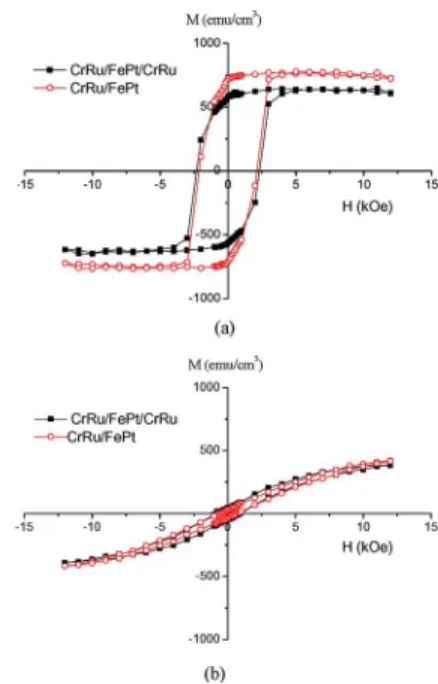
Fig. 2 shows the M-H loops of (a) in-plane and (b) out-plane of the CrRu(15 nm)/FePt(25 nm) and CrRu(15 nm)/FePt(25 nm)/CrRu(4 nm) films. Comparing Fig. 2(a) with Fig. 2(b), we can see that both of the CrRu/FePt and CrRu/FePt/CrRu films have excellent in-plane magnetic anisotropy. This is due to that the lattice misfit between CrRu(002)[100] and FePt(200)][110] is about 6.6% which leads the FePt(200) plane can epitax-ially grow along the CrRu(002) underlayer.
The Ms value of FePt films decreases from 730 emu/cm to 610 emu/cm as 4 nm CrRu capped layer is added, as shown in Fig. 2(a). This may be due to the diffusion of Cr and Ru atoms from capped layer into FePt layer through grain boundary, and Cr or Ru atoms react partially with Fe or Pt atoms, which
Fig. 2. The M-H loops of (a) in-plane (b) out-plane of the CrRu(15 nm)/FePt(25 nm) bilayer and CrRu(15 nm)/FePt(25 nm)/CrRu(4 nm) trilayer films which deposited at substrate temperature of 350 C.
results in decrease of Ms value. On the other hand, most of the Cr and Ru atoms are distributed at grain boundary of FePt that will increase the grain boundary energy and decrease the energy barrier of the transformation of FePt from soft -FePt to hard FePt phase. Therefore, adding CrRu capped layer on the FePt film will also enhance the degree of order of FePt layer. The decrease in Ms value of FePt layer as adding CrRu capped layer may be also ascribed the increase of FePt phase content in the film, because the Ms value of FePt phase is lower than that of -FePt phase[15]. Increase the amount of FePt phase in the FePt layer will enhance coercivity of FePt film, and therefore the value of FePt films increases from 2130 Oe to 2300 Oe when 4 nm CrRu capped layer is added, as shown in Fig. 2(a).
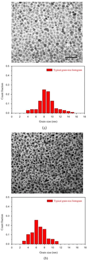
Fig. 3 are the TEM bright field images and grain size distri-bution of (a) CrRu(15 nm)/FePt(25 nm) and (b) CrRu(15 nm)/ FePt(25 nm)/CrRu(4 nm) films which deposited at substrate temperature of 350 C. It shows that the average grain size of the FePt film in CrRu(15 nm)/FePt(25 nm) bilayer is about 8.60 nm and the grain size distribution is large. When the 4 nm CrRu capped layer is added, the average grain size decreases to 6.61 nm and the film morphology shows narrow size distribution and the particles are isolated, as shown in Fig. 3(b). Several studies had shown that reduction of grain size and increasing the grain size uniformity would decrease the medium noise of thin film media [3], [16].Therefore, the Cr and Ru atoms diffuse from capped layer into FePt layer can reduce grain growth and ob-tain isolated FePt particles with uniform size that is beneficial to reduce exchange coupling of the magnetic grains and decrease medium noise of FePt film.
IV. CONCLUSION
Both the value and grain size of the FePt film are in-creased as a CrRu underlayer is introduced. Further adding a
878 IEEE TRANSACTIONS ON MAGNETICS, VOL. 43, NO. 2, FEBRUARY 2007
Fig. 3. The TEM bright field images and grain size distribution of (a) CrRu(15 nm)/FePt(25 nm) bilayer and (b) CrRu(15 nm)/FePt(25 nm)/CrRu(4 nm) trilayer films which deposited at substrate temperature of 350 C.
CrRu capped layer onto FePt film, the isolated FePt grains with uniform grain size are obtained and the of the FePt film is further increased, but the Ms value is decreased.
ACKNOWLEDGMENT
This work was supported by the National Science Council and Ministry of Economic Affairs of Taiwan through Grant NSC 94-2216-E-131-003 and 94-EC-17-A-08-S1-0006.
REFERENCES
[1] T. Suzuki and K. Ouchi, “Sputter-deposited (Fe-Pt)-MgO composite films for perpendicular recording media,” IEEE Trans. Magn., vol. 37, pp. 1283–1285, 2001.
[2] P. C. Kuo, S. C. Chen, Y. D. Yao, A. C. Sun, and C. C. Chiang, “Mi-crostructure and magnetic properties of nanocomposite FePtCr-SiN thin films,” J. Appl. Phys., vol. 91, pp. 8638–8640, 2002.
[3] J. G. Zhu, “Transition noise properties in longitudinal thin film media,”
IEEE Trans. Magn., vol. 29, pp. 195–200, 1993.
[4] Y. H. Lee, J. P. Wang, and L. Lu, “The role of amorphous Ni P precoating layer in CoCrPtTa thin film media,” J. Appl. Phys., vol. 87, pp. 6346–6348, 2000.
[5] C. M. Kuo and P. C. Kuo, “Magnetic properties and microstructure of FePt-Si N nanocomposite thin films,” J. Appl. Phys., vol. 87, pp. 419–426, 2000.
[6] S. C. Chen, P. C. Kuo, C. T. Lie, and J. H. Hua, “Microstructure and coercivity of granular FePt-AlN thin films,” J. Magn. Magn. Mater., vol. 236, pp. 151–157, 2001.
[7] Y. F. Ding, J. S. Chen, E. Liu, C. J. Sun, and G. M. Chow, “Effect of lattice mismatch on chemical ordering of epitaxialL1 FePt films,” J.
Appl. Phys., vol. 97, p. 10H303, 2005.
[8] C. C. Chiang, C.-H. Lai, and Y. C. Wu, “Low-temperature ordering of L1 FePt by PtMn underlayer,” Appl. Phys. Lett., vol. 88, p. 152508, 2006.
[9] S. Jeong, T. Ohkubo, A. G. Roy, D. E. Laughlin, and M. E. McHenry, “In situ ordered polycrystalline FePtL1 (001) nanostructured films and the effect of CrMn and Zn top layer diffusion,” J. Appl. Phys., vol. 91, pp. 6863–6865, 2002.
[10] B. C. Lim, J. S. Chen, and J. H. Yin, “Reduction of exchange coupling and enhancement of coercivity ofL1 FePt(001) films by Cu top layer diffusion,” Thin Solid Films, vol. 505, pp. 81–84, 2006.
[11] A. C. Sun, P. C. Kuo, S. C. Chen, C. Y. Chou, H. L. Huang, and J. H. Hsu, “Magnetic properties and microstructure of low ordering tem-peratureL1 FePt thin films,” J. Appl. Phys., vol. 95, pp. 7264–7266, 2004.
[12] D. H. Ping, M. Ohnuma, K. Hono, M. Watanabe, T. Iwasa, and T. Masumoto, “Microstructures of FePt-Al-O and FePt-Ag nanogranular thin films and their magnetic properties,” J. Appl. Phys., vol. 90, pp. 4708–4716, 2001.
[13] D. Weller, A. Moser, L. Folks, M. E. Best, W. Lee, M. F. Toney, M. Schwickert, J.-U. Thiele, and M. F. Doerner, “High Ku materials ap-proach to 100 Gbits/in ,” IEEE Trans. Magn., vol. 36, pp. 10–15, 2000. [14] B. Y. Wong, J. F. Ying, and K. Johnson, “Modeling of misfit induced defects in Co/Cr recording media,” IEEE Trans. Magn., vol. 36, pp. 2360–2362, 2000.
[15] T. Katayama, T. Sugimoto, Y. Suzuki, M. Hashimoto, P. dc Haan, and J. C. Lodder, “Magneto-optical Kerr rotation spectra in ordered and disordered phase of Fe-Pt alloy films,” J. Magn. Magn. Mater., vol. 104–107, pp. 1002–1004, 1992.
[16] I. Kaitsu, A. Inomata, I. Okamoto, and M. Shinohara, “Magnetic and R/W properties of CoPt–SiO granular media,” IEEE Trans. Magn., vol. 34, pp. 1591–1593, 1998.
Manuscript received August 10, 2006 (e-mail: [email protected]).