DFT-Modulated Filterbank Transceivers for Multipath
Fading Channels
See-May Phoong, Senior Member, IEEE, Yubing Chang, and Chun-Yang Chen
Abstract—The orthogonal frequency division multiplexing
(OFDM) transceiver has enjoyed great success in many wideband communication systems. It has low complexity and robustness against multipath channels. It is also well-known that the OFDM transceiver has poor frequency characteristics. To get transceivers with better frequency characteristics, filterbank transceivers with overlapping-block transmission are often considered. However these transceivers in general suffer from severe intersymbol interference (ISI) and high complexity. Moreover costly channel dependent post processing techniques are often needed at the receiving end to mitigate ISI. In this paper, we design discrete Fourier transform (DFT) modulated filterbank transceivers for multipath fading channels. The DFT modulated filterbanks are known to have the advantages of low design and implementation cost. Although the proposed transceiver belongs to the class of overlapping-block transmission, the only channel dependent part is a set of one-tap equalizers at the receiver, like the OFDM system. We show that for a fixed set of transmitting or receiving filters, the design problem of maximizing signal-to-interference ratio (SIR) can be formulated into an eigenvector problem. Experiments are carried out for transmission over random multipath channels, and the results show that satisfactory SIR performance can be obtained.
Index Terms—Filterbank, multicarrier, multitone, transceiver,
transmultiplexer.
I. INTRODUCTION
T
HE orthogonal frequency division multiplexing (OFDM) technique has enjoyed great success and popularity in both wireless and wired transmissions [1]. It has been adopted in standards for various applications such as the asymmetric dig-ital subscriber line (ADSL), very high bit rate digdig-ital subscriber line (VDSL), wireless local area networks (LANs), digital audio and video broadcasting, etc. Two of the attractive features of OFDM systems are low complexity and the ability to combat intersymbol interference (ISI). By adding a cyclic prefix of an appropriate length, frequency selective multipath channels are converted into a set of frequency nonselective subchannels using discrete Fourier transform (DFT) and inverse discrete Fourier transform (IDFT) matrices. The system requires only simple one-tap frequency domain equalizers at the receiver. However because the rectangular window is used as the pulse shaping filter in OFDM systems, the transmitting and receiving filters Manuscript received August 3, 2003; revised December 9, 2003. This work was supported by NSC 92-2219-E-002-015, Ministry of Education, under Con-tract 89-E-FA06-2-4, Taiwan, R.O.C. The associate editor coordinating the re-view of this manuscript and approving it for publication was Dr. Xiang-Gen Xia. The authors are with the Department of Electrical Engineering and the Grad-uate Institute of Communication Engineering, National Taiwan University, Taipei, Taiwan, R.O.C. (e-mail: smp@cc.ee.ntu.edu.tw).Digital Object Identifier 10.1109/TSP.2004.837399
suffer from very poor frequency responses. The stopband atten-uation is only 13 dB, and it decays at a rate of only. In many applications, it is often desired to have filters with better frequency responses. For many wireless communication sys-tems, it is desirable to have a transmitter with good frequency responses so that the transmitter output will have small out-of-band energy. For many wired wideout-of-band communication sys-tems, there is often narrowband radio frequency interference, and we will need better receiving filters to combat narrowband noise.
Many solutions have been proposed to improve the frequency characteristics of the OFDM transmitter or receiver. In [2]–[6], windowing or filtering methods have been introduced to reduce the out-of-band energy of OFDM transmitter outputs. Nonrect-angular continuous-time pulse shaping filters have been pro-posed to improve the spectral roll-off of the transmitted signals, e.g. [2] and [3]. Discrete-time windows have been considered in [4]–[6]. In [7] and [8], windowing techniques are applied to increase the stopband attenuation of the receiving filters. How-ever these windowing techniques often increase the number of redundant samples needed for removing ISI or amplify the re-ceiver output noise power.
In addition to the windowing technique, filterbank techniques have also been proposed to design transceivers with better trans-mitting and receiving filters. The connection of filterbank and transceiver is first recognized by Vetterli in [9]. It is shown that by interchanging the analysis and synthesis banks, one can ob-tain a transmultiplexer or a transceiver. Moreover, for AWGN channels, the transceiver is zero-forcing if the corresponding fil-terbank has perfect reconstruction (PR). In [10], the authors pro-pose the so called discrete wavelet multitone (DWMT) system, in which PR filterbank is used as the transceiver. The transmit-ting and receiving filters have excellent frequency separation property inherited from good filterbank designs. For frequency selective channels, there is intra-band as well as cross-band in-terference in these filterbank transceivers [9], [10]. Unlike the OFDM system, there is no simple equalization technique for DWMT systems.
One drawback of filterbank transceivers is their high com-plexity. To implement an -band filterbank transceiver, we need to implement transmitting filters and receiving filters. To reduce the complexity, DFT or cosine modulated filterbanks are often employed [11]–[15]. Modulated filterbank transceivers achieving ISI-free transmission over AWGN chan-nels have been considered in [11]–[14]. For multipath chanchan-nels, these transceivers are no longer ISI-free. Comparisons and performance evaluations of these modulated filterbank trans-ceivers have been conducted in [11], [12]. The results show that 1053-587X/$20.00 © 2005 IEEE
though the filterbank has near PR property, the ISI introduced by the channel can seriously degrade the system performance. To reduce the amount of ISI, intra- and cross-band equalization are performed on the receiver outputs in [10] and [13]. In [15], the problem of complicated equalization is overcome by introducing cyclic prefix to the filterbank transceiver. However, frequency responses of some of the transmitting and receiving filters are seriously affected by the insertion of cyclic prefix.
There have been attempts to design ISI-free filterbank trans-ceivers for frequency selective channels [16]–[20]. However, these design methods assume that the exact channel impulse responses are known. Moreover, except for [17], the min-imum-mean-square-error (mmse) solutions are studied, and the resulting transmitting and receiving filters do not have good frequency responses. In [17], the authors propose a method for designing ISI-free filterbank transceivers using paraunitary or unimodular matrices. However, the optimization involves a highly nonlinear objective function. As we have mentioned ear-lier, one of the most attractive features of OFDM systems is the ability to attain ISI-free property for unknown multipath chan-nels. Most of the previously proposed filterbank transceivers do not enjoy this feature. Therefore, it is of tremendous interest in studying filterbank transceivers with such a property. A non DFT-based transceiver with such a property, called A Mutually Orthogonal Usercode Receiver (AMOUR) transceiver, has been introduced in [21]. By judiciously selecting the zeros of the transmitting filters and employing a corresponding Vander-monde receiving filters, the authors show how the AMOUR transceiver can achieve ISI-free for unknown channels. The AMOUR transceiver belongs to the class of block transmission schemes; its transmitting filters and receiving filters cannot be longer than the upsampling and downsampling ratio. Moreover there is no simple method to design AMOUR transceivers with good frequency responses.
In this paper, we design filterbank transceivers for multipath fading channels. We mainly focus on DFT modulated filterbank transceivers. The DFT modulated filterbanks are known to have the advantages of low design and implementation cost. Although the proposed transceiver belongs to the class of overlapping-block transmission, the only channel dependent part is a set of one-tap equalizers at the receiver, like the OFDM system. For a set of good receiving filters, the transmitting prototype filter can be optimized so that SIR is maximized. Conversely, we can also design the receiving prototype filter to maximize SIR given transmitting filters. We show that such an optimization problem can be formulated as a Rayleigh-Ritz ratio, whose solution is well known [22]. Moreover, we will prove that for the multipath channels, given that the transmitting (or receiving) filters are DFT modulated filters, the assumption of DFT modulated receiving (or correspondingly transmitting) filters is no loss of generality. Simulation results show that DFT modulated filterbank transceivers with satisfactory SIR value can be obtained.
The paper is organized as follows. In Section II, we will de-rive the ISI-free conditions for DFT modulated filterbank trans-ceivers and show that these conditions can be formulated using a matrix representation. The optimization of the transceivers is studied in Section III. We will derive the SIR expressions
and show that they can be rewritten as a Rayleigh-Ritz ratio. The problem of designing the SIR optimized filterbank trans-ceiver without frequency constraint is studied in Section IV In Section V, simulation results are given to demonstrate the use-fulness of the proposed transceivers. Conclusions are given in Section VI.
Notations:
1) Boldfaced lower case and upper case letters are used to denote vectors and matrices, respectively. The notations , , and denote, respectively, the transpose, com-plex conjugate, and transpose-conjugate of the matrix . 2) For any positive integer and any integer , the
nota-tion represents , which is a number
between 0 and .
3) The by DFT matrix is denoted by . The th
entry of is , where .
4) The unit impulse sequence is denoted by . It is equal
to 1 when and 0 otherwise.
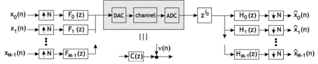
II. ISI-FREEDFT MODULATEDFILTERBANKTRANSCEIVERS Fig. 1 shows a filterbank transceiver. The number of subbands is and the downsampling and upsampling ratio is . We assume that so that ISI-free solution is possible. The number represents the number of redundant samples added to combat intra-band and cross-band ISI. The filters and are respectively the transmitting and receiving filters. In this paper, we consider only fininte impulse response (FIR) filters with
where and are, respectively, the length of
the transmitting and receiving filters. The values of and can be larger than . So our study also includes the case of overlapping block transmission. The purpose of adding at the receiver will be explained later. For notational simplicity, we have used the noncausal expression for the receiving filters. Causal filters can be easily obtained by adding enough delays. We say that the filterbank transceiver is ISI-free1if in the
ab-sence of noise ,
for
for some constants . In this case, a zero-forcing solution can be obtained by cascading a simple one-tap equalizer of at each subband.
The complexity of a general filterbank transceiver as shown in Fig. 1 is very high. At the transmitter and receiver, we need to implement filters of orders and , respectively. In many applications, such a high cost might not be justified. To reduce the complexity, we consider DFT modulated filters in this paper:
and
where (1)
1The most general ISI expression should be^x (n) = G x (n 0 n ). For
notational simplicity, we taken = 0 in this paper. This is of course a slight loss of generality.
Fig. 1. Filterbank transceiver.
for . Note that even though the decimation ratio
is , the filters are shifted by integer multiples of . The implementational cost of the DFT modulated filterbank trans-ceiver is very low. At the transmitter (or retrans-ceiver), we only need to implement a prototype filter of order (or correspondingly order ) and an by DFT matrix that can be implemented efficiently using fast Fourier transform. In addition to low im-plementational cost, the DFT modulated filterbank transceiver has low design cost. We need only to design one prototype filter at the transmitter and the receiver. Moreover in some cases, there is no loss of generality in using DFT modulated filters (see Theorem 1).
In many applications, it is often desired to have transmitting filters or receiving filters with good frequency responses. For many wireless communication systems, we would like to have transmitting filters with better frequency responses so that the transmitter outputs will have smaller out-of-band energy. In this case, is designed to be a good lowpass filter and will be good bandpass filters. On the other hand, for many wired communication systems, better receiving filters are often needed to combat narrowband radio frequency interference (RFI) noise. In this case, is designed to be a good lowpass filters, and will be good bandpass filters. Depending on appli-cations, our design problem is either 1) given a good lowpass transmitting prototype filter , design the receiving proto-type filter to achieve the ISI-free property or SIR maxi-mization, or 2) given a good lowpass receiving prototype filter , design the transmitting prototype filter to achieve the ISI-free property or SIR maximization. As we will see later, interchanging the transmitting filters with the receiving filters will not affect the ISI-free property of the transceiver. Problem 1 can be easily formulated into Problem 2, and vice versa, by interchanging the roles of transmitting and receiving filters. In this paper, we will consider Problem 2 only. Hence, in this section and in Section III, is a predetermined good lowpass filter.
In this paper, the transmission channel is assumed to be slowly varying and that it can be modeled as an FIR linear time invariant (LTI) channel and an additive noise , as shown in Fig. 1. Let be the maximum possible order of the
channel . Then, can be expressed as
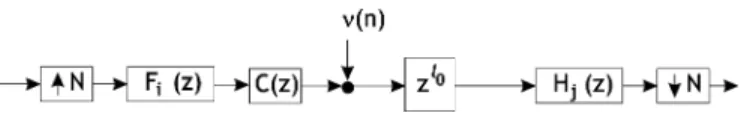
Unlike the OFDM and other block transmission systems, the order of the channel can be larger than the number of redun-dant samples . Fig. 2 shows the transfer function from
the th input to the th output. It is known [23] that the system in Fig. 2 is LTI with transfer function
(2) where the notation denotes -fold downsampling. We
express the term as
(3)
for and . It can be verified that
the sequences and have approximately
nonzero coefficients, where denotes the largest integer that is smaller than . For convenience, we define
for all (4)
Because the transmitting filters and receiving filters are DFT modulated versions of the respective prototype filters and , it turns out that and also satisfy a similar relation. The result is stated in the following lemma. A proof is given in Appendix A.
Lemma 1: For DFT modulated filterbank transceivers with filters defined in (1), the sequences and defined in (3) satisfy
where represents modulo .
To have the ISI-free property, the transfer functions should satisfy
otherwise.
If and are such that the transceiver is ISI-free for any channel of order , then we see from (2) that
and should satisfy
otherwise (5)
for all . In other words, and
for all . Whenever we have
for or , then and contribute
respectively to the intra-band ISI and the cross-band ISI. Note that the ISI-free condition in (5) is also satisfied by
Fig. 2. Transfer function from theith input to the jth output.
the AMOUR transceiver [21]. In the AMOUR transceiver, the ISI-free property is achieved by judiciously selecting the zeros of the transmitting filters and employed a corresponding set of Vandermonde receiving filters.
Using Lemma 1, one can verify that the ISI-free condition can be further simplified as
(6) for all . When the filterbank transceiver achieves the ISI-free condition in (6), any frequency selective channel with order is converted into a set of parallel frequency nonselective subchannels. The gain of the th subchannel is given by
(7) Even though the conditions in (6) only say that the input se-quence of the 0th band will not cause any interference to other subbands, this condition alone is enough to guarantee the ISI-free property of the transceiver when the filters are DFT modulated filters.
Matrix Form of the ISI Condition: Given a fixed receiving
prototype filter , the parameters and
can be written as a linear combination of the impulse response . Therefore, we can write
..
. ... (8)
..
. ... (9)
where the by matrices and are
given in Appendix B. Define the vectors
..
. ...
Then, the ISI-free conditions in (6) can be written as
One can write the above conditions as a single matrix equation:
When the desired parameters are known, one can use the least square method to solve the above linear equations and obtain
(10) Note that this least square solution is different from the conven-tional MMSE solution. In the above design, we do not consider channel noise, and hence, is independent of the channel and noise. In many applications, it is desired to have trans-ceivers that maximize SIR. The optimal that maximizes SIR is not known yet. In Section III, we will show that the design of that maximizes SIR can be formulated as an eigenproblem that has a well-known solution.
On the Choice of : The relation between and the subchannel gain is given in (7). If are known, let
. One intuitive choice of is
otherwise.
In many applications, might not be available. Then one can
select for all . Using (7), we have
(11)
where are the M-point DFT coefficients of .
The subchannel gains are the same as those in the OFDM system, except for a unit-magnitude constant. Note that in
this case, ; the channel energy is
preserved by the transceiver.
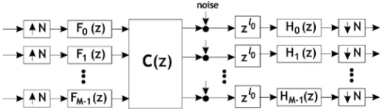
Filterbank Transceivers for Unknown MIMO Channels: The ISI-free filterbank transceivers presented above remain ISI-free when the channel is a MIMO LTI system. To see this, consider Fig. 3, where is an by transfer matrix of order .
Let the th element of be .
Then, the transfer function from the th input to the th output becomes
If the filters and satisfy (5), then it is clear that continues to satisfy the ISI-free condition in (5) for any MIMO channels of order .
Remark: Although we consider only DFT modulated trans-mitting and receiving filters, the derivation for the case of more general transmitting and receiving filters is very similar.
III. SIR OPTIMIZEDTRANSCEIVERS
In this section, we will consider the case when is some predetermined good lowpass filter so that the receiving filters have good frequency responses. We will design the transmit-ting prototype filter so that the signal-to-interference ratio (SIR) is maximized. We first design transceivers that optimize the SIR when the exact channel impulse responses are known.
Fig. 3. Filterbank transceiver for MIMO channel.
Then transceivers optimized for unknown multipath channels will be considered. In the following derivations, we assume that the input signals are uncorrelated, zero-mean, wide sense stationary, and white random processes with the same variance
. In other words
This mild assumption can be satisfied by properly interleaving the input data.
A. SIR Optimized Transceivers for Known Channels
In this subsection, we assume that the exact channel impulse responses are known. Recall the definitions of and in (3). Using these definitions, the output of the th subband can be expressed as
where “ ” denotes convolution, and we have used the defini-tion of in (4). We see that the three terms on the right hand side of the above expression are respectively the de-sired signal, the intra-band ISI and the cross-band ISI. Under the assumption of uncorrelated input signals, the signal power and interference power at the th subband are, respectively, given by (12)
(13) Note that both the signal power and interference power depend on the channel impulse response . Using (12) and (13), we can write SIR as (14), shown at the bottom of the page, where
the subscript means that this is the SIR for a fixed
transmis-sion channel . If is known, we can design to
maximize SIR . In what follows, we will show that SIR can be formulated as a Rayleigh-Ritz ratio [22]. Using the results from Lemma 1, we can write the numerator of SIR as
where denotes the 2-norm of the vector . The matrix is an by matrix, which consists of the first
column vectors of the by DFT matrix , and
the diagonal matrix . Using (8),
we have
Similarly one can express the first and second terms of the de-nominator of SIR , respectively, as
where we have used the fact that , which is a direct consequence of the definition . Define the matrix
Then, SIR can be rewritten as SIR
Note that both and are semidefinte matrices. Thus, the best that maximizes the SIR is given by
Except for some special cases, the matrix is invertible.
De-composing as for some positive definite matrix
and letting , the above optimization problem can be rewritten as
Using Rayleigh–Ritz theorem [22], we immediately get the
op-timal solution as , where is the
eigen-vector corresponding to the largest eigenvalue of . B. SIR Optimized Transceivers for Multipath Fading Channels In many applications, the exact channel impulse responses might not be available, and we may have only the statistics of the transmission channels. Consider multipath fading channels with
taps for . Assume that the coefficients
are complex random variables that satisfy
(15) for . In other words, the coefficients are zero mean and uncorrelated. We consider the average signal power and the average ISI power. At the output of the th band, the average powers of signal and interference term are, respectively, defined as
where means that the expectation is taken with respect to . Using (12) and (13) and the results in Lemma 1, these average powers can, respectively, be expressed as
where we have used the fact that
for all to simplify the expression for . It is interesting to note that these average powers are independent of ; all the subbands have the same average signal and inter-ference powers. The average SIR is therefore given by
SIR
(16) Our goal is to design so that SIR is maximized. We can for-mulate SIR as a Rayleigh–Ritz ratio. Using an approach similar to the earlier derivation, one can verify that we can express the 3 summations in the expression of SIR, respectively, as
where the diagonal matrix diag . From
the above expressions, one can form the Rayleigh-Ritz ratio and solve for the optimal that maximizes SIR. As our goal is to find FB transceiver that minimizes ISI for multipath fading channels, we do not consider channel noise in the optimization. Thus the resulting solution is different from the conventional MMSE solution because it is independent of the exact channel impulse response and the noise.
iid Channels2: When the taps of channel response are
independent and identically distributed (iid) random variables, the average SIR can be obtained from SIR by setting for all
SIR
(17) Note that in this case, the average SIR becomes channel inde-pendent; the optimal transceiver is also channel independent.
On the Choice of : Note that the matrices and depend on the choice of the integer . In the optimization process, one has to search for the best to maximize the objective function. Because the upsampling and downsampling ratio is , there is no need to search for a range that is larger than . In our simulations, we find that the best falls within
the range of .
In the above optimizations, it is assumed that the transmitting filters are DFT modulated filters and hence we need only to design one prototype filter . This is in general a loss of generality. However for multipath fading channels that satisfy (15), we can show that there is no loss of generality in using DFT modulated transmitting filters if the receiving filters are DFT modulated filters. This result is stated more precisely in the following theorem.
2This is often the channel model that we used in designing transceiver when
Theorem 1: Suppose that the channel impulse re-sponses satisfy (15). If the receiving filters are DFT modulated filters, then the optimal transmitting filters that maximize the average
SIR satisfy for some unit magnitude
constant .
Proof: When the transmitting filters are not DFT modu-lated versions of a prototype filter, the sequences and do not satisfy the relations described in Lemma 1 and hence the SIR in (17) is no longer valid. In this case, the
av-erage SIR depends on and . One can verify that
it is given by
SIR
Let us rewrite the average SIR as SIR
where the non-negative quantities and are, respectively, defined by
From the definitions of and in (3), we can
im-mediately see that and depend only on the th transmitting
filter , and affects only and . Define3
(18) Then, the problem of finding the set
to maximize SIR is equivalent to finding each individual transmitting filter to maximize . Suppose
that maximizes . Let be the corresponding
maximum SIR value and let and be the
corresponding sequences. Then we would like to show that for any unit magnitude constant opti-mizes . Note that when is a frequency shifted version of , from Lemma 1, we know that the corresponding
sequences and will have the same magnitude
as and respectively. From the
expres-sion of , we can conclude that when ,
. Now, suppose that
is not an optimal solution; there exists an such that
the corresponding is larger than . Then, by
let-ting and using a similar procedure,
one can show that we will get , which is larger
than , which is a contradiction! Hence, the choice of
is optimal. QED
3Note that can be viewed as SIR of the transceiver when only x (n) is
sent, i.e.x (n) = 0 for all j 6= i.
IV. SIR OPTIMIZEDTRANSCEIVERSWITHOUTFREQUENCY RESPONSECONSTRAINTS
In previous sections, it is assumed that the receiving proto-type is predetermined as a good lowpass filter so that the receiving filters will have good frequency responses. There may be applications for which neither the transmitting filters nor the receiving filters need to have good frequency responses. In this
case, our goal is to design both and so that SIR
is maximized. However the problem of simultaneous optimiza-tion of and is highly nonlinear. We adopt the it-erative approach proposed in [19] to solve the problem. Given , we know how to design using results in Section III. Given , one can in fact use a similar procedure to design . The reason is as follows. Observe from (2) that we can interchange the filters and without affecting the ISI-free property of the transceiver. Hence by replacing with and using the same techniques described in Sec-tions II and III, we can obtain expressions of , SIR and
SIR in terms of . Therefore, given , the optimal
can be solved in a similar procedure.
The iterative procedure similar to that in [19] for designing and is as follows. The filter is initialized as a good lowpass filter or any simple filter. For , do the following.
a) Given , optimize so that or SIR is
maximized depending on how much channel information is available.
b) Given , optimize so that or SIR is
maximized depending on how much channel information is available.
c) If is equal to the maximum number of iterations, or SIR is higher than the desired value or the difference
be-tween , and those of the previous iteration
is smaller than some fixed value, stop. Else, , and go to a).
Note that the resulting SIR is a nondecreasing function of the number of iterations. However, it is not guaranteed to converge to the global maximum.
V. SIMULATIONRESULTS
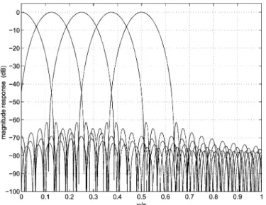
In this section, we provide six examples to demonstrate our results. In the first four examples, we consider the case when the receiver filters have good frequency responses. The receiving prototype filter is a unit norm lowpass filter designed using the eigenfilter method [24]. The coefficients are designed to minimize
It is found in the experiments that by choosing as a number slightly larger than , we will get satisfactory results. In the fifth example, we consider the case when there is no fre-quency response constraint on , and we design and using the proposed iterative procedure. The transmission
Fig. 4. Magnitude response of the first five receiving filters.
Fig. 5. SIR versus transmitting filter order.
channels are multipath fading channels with
taps. The coefficients are independent circular complex Gaussian random variables with variances . We have used 10 000 random channels in the experiments. Given and , the SIR values in our plots (except Example 6) are the average value over these 10 000 channels, as shown in the equation at the bottom of the page. In Example 6, only 200 randomly chosen channels are employed in the simulation due to the complexity limitation.
Example 1: In this example, , and .
The multipath channel is iid. So are the same for all . The order, stopband edge, and stopband attenuation of
transmitter prototype filter are respectively , and 61 dB. The plot of the magnitude responses of the first five receiving filters are shown in Fig. 4. First, we con-sider (i) DFT modulated transmitting filters maximizing SIR, (ii) general (non-DFT modulated) transmitting filters,
, maximizing SIR, and (iii) DFT modulated transmitting filters designed by the least square method in (10).
For the least square method, for , we choose
[choosing as the DFT coefficients as in (11) gives a worse performance]. We plot SIR versus and the results are shown in Fig. 5. From the figure, we see that the maximized SIR method always outperforms the least square method. The SIR performance of general transmitting filters is identical to that of DFT modulated transmitting filters. Hence, by choosing DFT modulated filters we do not lose any perfor-mance as explained in Theorem 1. When increases, SIR in-creases. Moreover for moderate filter orders of , e.g., 20, 40 and 60, we are able to obtain SIR values of 14.5, 17, and 19.5 dB respectively. Fig. 6 shows the performance of SIR optimized transceiver versus , the stopband edge of the receiving
proto-type filter . The filters order . We see from
the figure that the SIR value varies with , but it is not very
sensitive to the choice of . The optimal .
Example 2: We set , and . The
stopband edge for is . The multipath channels
are iid channels with taps. We plot the SIR performance of the transceivers versus . The SIR curves are shown in Fig. 7. From the figure, we see that the SIR performance de-grades gradually with respect to . Even when is larger than
the number of redundant samples , we can have
a moderate SIR performance. Note that when the channel is a frequency nonselective channel, i.e., when the number of taps is , the transceiver is not ISI-free. This is because the DFT modulated filterbanks of the form in (1) cannot achieve PR with FIR prototype filters [23].
Example 3: In this example, we design transceiver with
and . The receiving prototype filter has
, and a stopband attenuation of more
than 61 dB. The random channels are iid channels with taps. The SIR curves for , 8, 16 are shown in Fig. 8. We can still have a moderate SIR value when is 64.
Example 4: We take , and . The
vari-ances of are . We consider transceivers
that optimize i) SIR in (14), ii) SIR in (16), and iii) SIR in (17), respectively. In Case i), we design an optimal transceiver for each of the 10 000 random channels, whereas in Cases ii) and iii), we design only one optimal transceiver. In Case ii), we assume that the variance is known and it is incorporated in the design. In Case iii), the transceiver is designed for iid
chan-nels although the actual variance is . The cost
Fig. 6. Performance of SIR optimized transceivers versus stopband edge of H (z).
Fig. 7. SIR optimized 16-band transceivers designed for iid channels withL+ 1 taps.
of designing optimal transceivers for known channels is signif-icantly higher than those in Cases ii) and iii). The results are shown in Fig. 9. As we might expect, if the exact channel im-pulse responses are known, the transceiver will have the best SIR performance. Comparing Cases i) and ii), the improvement is not significant. If we compare Cases ii) and iii), we can ob-tain a moderate gain. Hence, incorporating the variance in the design can significantly increase the SIR performance without much increase in design cost.
Example 5: In this example,4we compare the bit rate
perfor-mance of the proposed transceivers. The system parameters are the same as those in Example 3. A total of 200 sets of iid chan-nels are employed in the simulations. We consider two cases where the channel noise is a complex AWGN with variance
4We would like to thank T.-H. Luo, a graduate student in the Graduate
In-stitute of Communications Engineering at the National Taiwan University, for generating this example.
Fig. 8. SIR optimized 64-band transceivers designed for iid channels withL+ 1 taps.
Fig. 9. Performance of transceivers designed using different degrees of channel information.
with and without narrowband interference (NBI). The
narrow-band noise is modeled as . We consider the
transmission rate under a fixed probability of symbol error of . We plot (number of bits per block) versus SNR (which is given by , where is the symbol energy). The quan-tity is given by [25]
SNR
where denotes the largest integer that is smaller that , and SNR is the SNR at the output of the th subchannel. The re-sults are given in Fig. 10. From the figure, we see that when there is no NBI, the conventional OFDM system performs better that the proposed DFT transceiver. The difference increases when SNR increases. In the absence of NBI, the output error due to AWGN is the same for both systems. The conventional OFDM system is ISI-free whereas the proposed DFT transceiver suffers
Fig. 10. Comparison of bit rate.
Fig. 11. Performance of SIR optimized transceivers designed using the iterative approach.
from residue ISI. At high SNR, the performance of the proposed transceiver is limited by the ISI effect. On the other hand, the presence of NBI has little effect on the performance of the pro-posed transceiver whereas the performance of the conventional OFDM system degrades significantly when there is NBI.
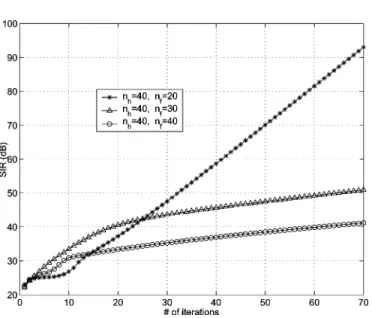
Example 6: In this example, , , ,
and . The transmitting prototype filter is initialized as the lowpass filter in Example 1. The channels are iid channels. Using the iterative procedure described in Section IV,
we design both and to optimize the average SIR.
The results are shown in Fig. 11 for , 30, and 40. Note that SIR values can be as high as 50 dB. For the case of , the transmitter reduces to a block transmission scheme, and it is found that the solution converges to the conventional OFDM scheme.
VI. CONCLUSIONS
In this paper, we consider DFT modulated filterbank trans-ceivers. Given a fixed receiving (or transmitting) prototype filter, we have shown that the problem of finding the best transmitting (or correspondingly receiving) prototype filter that maximizes the SIR can be formulated as a Rayleigh–Ritz ratio. The optimal prototype filter can be obtained as the eigenvector corresponding to the largest eigenvalue of an associated pos-itive definite matrix. For multipath fading channels, we show that there is no loss of generality in assuming that the optimal transmitting filters are DFT modulated version of a prototype filter. Simulations of transmission over random multipath chan-nels have been carried out and the results have demonstrated the usefulness of the proposed transceiver.
APPENDIX A
PROOF OFLEMMA1
We will prove the relation for . The proof for is very similar. Substituting (1) into the expression for in (3), for , we get5
From the above expression, we immediately get the relation for .
APPENDIX B
EXPRESSIONS FOR AND
For convenience, we define whenever .
From the definitions of and , one can verify
that the matrices and are, respectively, given by the equation shown at the top of the next page, where
.
ACKNOWLEDGMENT
The authors would like to thank Prof. Y.-P. Lin at the De-partemtn of Electrical and Control Engineering, National Chiao Tung University, Hsinchu, Taiwan, for helpful discussions and suggestions.
5Fori = j, the relation of (n) described in Lemma 1 is trivially true by
..
. ... . .. ...
..
. ... . .. ...
REFERENCES
[1] R. van Nee and R. Prasad, OFDM for Wireless Multimedia
Communi-cations. Boston, MA: Artech House, 2000.
[2] A. Vahlin and N. Holte, “Optimal finite duration pulses for OFDM,”
IEEE Trans. Commun., vol. 44, pp. 10–14, Jan. 1996.
[3] K. Matheus and K.-D. Kammeyer, “Optimal design of a multicarrier systems with soft impulse shaping including equalization in time or fre-quency direction,” in Proc. IEEE Global Telecommun. Conf., vol. 1, Nov. 1997, pp. 310–314.
[4] R. W. Lowdermilk, “Design and performance of fading insensitive or-thogonal frequency division multiplexing (OFDM) using polyphase fil-tering techniques,” in Conf. Rec. Thirtieth Asilomar Conf. Signals,
Sys-tems Computers, Nov. 1996.
[5] M. Pauli and P. Kuchenbecker, “On the reduction of the out-of-band radiation of OFDM-signals,” in Proc. IEEE Int. Conf. Commun., vol. 3, June 1998, pp. 1304–1308.
[6] Y. P. Lin and S. M. Phoong, “Window designs for ISI-free OFDM sys-tems,” IEEE Trans. Signal Process., to be published.
[7] S. Muller-Weinfurtner and J. Huber, “Optimum Nyquist windowing for improved OFDM receivers,” in Proc. IEEE Global Telecomm. Conf., Nov. 2000, pp. 711–715.
[8] A. J. Redfern, “Receiver window design for multicarrier communication systems,” IEEE J. Sel. Areas Commun., pp. 1029–1036, June 2002. [9] M. Vetterli, “Perfect transmultiplexers,” in Proc. IEEE Int. Conf. Acoust.
Speech Signal Process., Apr. 1986, pp. 2567–2570.
[10] S. D. Sandberg and M. A. Tzannes, “Overlapped discrete multitone mod-ulation for high speed copper wire communications,” IEEE J. Sel. Areas
Commun., vol. 13, pp. 1571–1585, Dec. 1995.
[11] A. D. Rizos, J. G. Proakis, and T. Q. Nguyen, “Comparison of DFT and cosine modulated filterbanks in multicarrier modulation,” in Proc. IEEE
Global Telecommun. Conf., 1994, pp. 687–691.
[12] S. Govardhanagiri, T. Karp, P. Heller, and T. Nguyen, “Performance analysis of multicarrier modulations systems using cosine modulated fil-terbanks,” in Proc. ICASSP, Mar. 1999, pp. 1405–1408.
[13] N. J. Fliege and G. Rosel, “Equalizer and crosstalk compensation filters for DFT polyphase transmultiplexer filterbanks,” in Proc. ISCAS, 1994. [14] H. Bolcskei, P. Duhamel, and R. Hleiss, “Design of pulse shaping OFDM/OQAM systems for high data-rate transmission over wireless channels,” in Proc. IEEE Int. Conf. Commun., 1999.
[15] C. Y. Chen and S. M. Phoong, “Zero forcing cosine modulated filterbank transceivers with cyclic prefix,” in Proc. Second Int. Workshop Spectral
Methods Multirate Signal Process., Toulouse, France, Sep. 2002.
[16] A. Scaglione, G. B. Giannakis, and S. Barbarossa, “Redundant filterbank precoders and equalizers part I: unification and optimal designs,” IEEE
Trans. Signal Process., vol. 47, pp. 1988–2006, Jul. 1999.
[17] Y. P. Lin and S. M. Phoong, “ISI free FIR filterbank transceivers for frequency selective channels,” IEEE Trans. Signal Process., vol. 49, pp. 2648–2658, Nov. 2001.
[18] C. B. Ribeiro, M. L. R. de Campos, and P. S. R. Diniz, “FIR equalizers with minimum redundancy,” in Proc. Int. Conf. Acoust., Speech, Signal
Process., May 2002.
[19] A. Hjorungnes, P. S. R. Diniz, and M. L. R. de Campos, “Jointly min-imum MSE transmitter and receiver FIR MIMO filters in the presence of near-end crosstalk and additive noise,” in Proc. Int. Symp. Circuits Syst., May 2003.
[20] A. Hjorungnes and P. S. R. Diniz, “Jointly minimum symbol error rate FIR MIMO transmitter and receiver filters for PAM signal vectors,” in
Proc. Int. Symp. Circuits Syst., May 2003.
[21] G. B. Giannakis, Z. Wang, A. Scaglione, and S. Barbarossa, “AMOUR—generalized multicarrier transceivers for blind CDMA re-gardless of multipath,” IEEE Trans. Commun., vol. 48, pp. 2064–2076, Dec. 2000.
[22] R. A. Horn and C. R. Johnson, Matrix Analysis. Cambridge, U.K.: Cambridge Univ. Press, 1985.
[23] P. P. Vaidyanathan, Multirate Systems and Filterbanks. Englewood Cliffs, NJ: Prentice-Hall, 1993.
[24] P. P. Vaidyanathan and T. Q. Nguyen, “Eigenfilters: a new approach to least-squares FIR filter design and applications including Nyquist fil-ters,” IEEE Trans. Circuits Syst., vol. CAS-34, pp. 11–23, Jan. 1987. [25] T. Starr, J. M. Cioffi, and P. J. Silverman, Understanding Digital
Sub-scriber Line Technology. Englewood Cliffs, NJ: Prentice-Hall, 1999.
See-May Phoong (M’96–SM’03) was born in Johor, Malaysia, in 1968. He received the B.S. degree in electrical engineering from the National Taiwan University (NTU), Taipei, Taiwan, R.O.C., in 1991 and the M.S. and Ph.D. degrees in electrical engi-neering from the California Institute of Technology (Caltech), Pasadena, in 1992 and 1996, respectively. He was with the Faculty of the Department of Elec-tronic and Electrical Engineering, Nanyang Techno-logical University, Singapore, from September 1996 to September 1997. In September 1997, he joined the Graduate Institute of Communication Engineering and the Department of Elec-trical Engineering, NTU, as an Assistant Professor, and since August 2001, he has been an Associate Professor. His interests include multirate signal pro-cessing and filterbanks and their application to communications.
Dr. Phoong is currently an Associate Editor for the IEEE SIGNALPROCESSING
LETTERS. He served as an Associate Editor for the EEE TRANSACTIONS ON
CIRCUITS ANDSYSTEMSII from January 2002 to December 2003. He received the Charles H. Wilts Prize in 1997 for outstanding independent research in elec-trical engineering at Caltech.
Yubing Chang was born in Kaoshiung, Taiwan, R.O.C., in 1979. He received the B.S. degree in me-chanical engineering from the National Cheng Kung University, Tainan, Taiwan, in 2001 and the M.S. degree in electrical engineering from the National Taiwan University, Taipei, in 2003.
Chun-Yang Chen was born in Taipei, Taiwan, R.O.C., in 1977. He received the B.S. and M.S. degree in electrical engineering from the National Taiwan University (NTU), Taipei, in 2000 and 2002, respectively.
His interests include multirate signal processing, multicarrier communication and audio coding.