Reduction of electronic delay in active noise control systems—
A multirate signal processing approach
Mingsian R. Bai,a)Yuanpei Lin, and Jienwen Lai
Department of Mechanical Engineering, National Chiao-Tung University, 1001 Ta-Hsueh Road, Hsin-Chu 300, Taiwan, Republic of China
共Received 30 November 2000; accepted for publication 5 November 2001兲
Electronic delay has been a critical problem in active noise control 共ANC兲 systems. This is true whether a feedforward structure or a feedback structure is adopted. In particular, excessive delays would create a causality problem in a feedforward ANC system of a finite-length duct. This paper suggests a multirate signal-processing approach for minimizing the electronic delay in the control loop. In this approach, digital controllers are required in decimation and interpolation of discrete-time signals. The computation efficiency is further enhanced by a polyphase method, where the phases of low-pass finite impulse response 共FIR兲 filters must be carefully designed to avoid unnecessary delays. Frequency domain optimization procedures based on H1, H2, and H⬁norms, respectively, are utilized in the FIR filter design. The proposed method was implemented by using a floating-point digital signal processor. Experimental results showed that the multirate approach remains effective for suppressing a broadband 共200–600 Hz兲 noise in a duct with a minimum upstream measurement microphone placement of 20 cm. © 2002 Acoustical Society of America. 关DOI: 10.1121/1.1432980兴
PACS numbers: 43.50.Ki关MRS兴
NOMENCLATURE
ps p equivalent primary pressure source
psa equivalent secondary pressure source
Zs p equivalent primary source impedance
Zsa equivalent secondary source impedance
Z0 radiation impedance at the duct opening
C(z) digital filter of active controller Hd(ej) frequency response template
Bl electromagnetic transduction constant zM mechanical mobility of loudspeaker uc, fc cone velocity and force
I. INTRODUCTION
Active control for noise in ducts has been investigated by researchers in the area of active noise control 共ANC兲 for decades.1– 4 A great majority of ANC systems to date has been realized by digital systems.4Although digital systems provide many advantages over the analog counterpart, they suffer from several design constraints. In particular, the elec-tronic delay during analog-to-digital 共AD兲 conversion and digital-to-analog共DA兲 conversion, low-pass antialiasing and reconstruction 共or smoothing兲 filtering has been a critical problem in active noise control systems. These delays along with other inherent delays resulting from computation and transducer dynamics might pose design constraints on ANC systems, which could become quite severe when the applica-tion of interest has strict space limitaapplica-tion, e.g., active muf-flers for motorcycles. These design constraints apply to both feedback control and feedforward control. Specifically, ex-cessive delays would limit the achievable performance and stability margin in a feedback ANC system.5 Causality is usually not a problem for periodic signals so long as the controller has a long enough impulse response to produce the properly phased cancellation filter. In conventional signal-processing applications, delay is usually not an important
issue. Pure delay is usually tolerated because the waveform is preserved. However, delay becomes crucial in control sys-tems, especially for ANC applications that generally involve relatively large bandwidth. Excessive delays could create causality problems in a feedforward ANC system of a finite length duct if the noise of concern is broadband and random in nature. Causality constraint refers to the condition under which the delay in the acoustical path is greater than the electronic path such that the resulting controller is causal and hence implementable. Under the causality constraint, delays in low sampling rate systems generally result in impractical requirement on physical dimension.1,4
To combat the delay problem in the control loop, this paper proposes a digital signal-processing scheme based on the multirate concept that is a fast growing area in many applications.6,7 In this approach, digital controllers are re-quired in decimation and interpolation of discrete-time sig-nals. To enhance computation efficiency, a polyphase method is employed in filter design.8 –10 In the multirate ANC sys-tem, a factor of 8 was used for upsampling and downsam-pling. This resampling process raises the nominal sampling frequency of controller 2 kHz to 16 kHz during AD/DA con-version, which significantly reduces the sample delays. As a crucial part in the polyphase design, the phases of low-pass finite impulse response 共FIR兲 filters must be carefully de-signed to avoid unnecessary delays. To this end, optimization a兲Electronic mail: [email protected]
procedures in frequency domain based on H1, H2, and H⬁ norms, respectively, are utilized in the design.11–13
One fundamental question may be naturally raised: why not simply run the ANC system at a very high sampling rate? Delay would then be low, and there would be no need for the multirate filters at all. Unfortunately, there are several subtle points that may prohibit the use of this seemingly straight-forward approach. First, the effective control bandwidth for the physical system would only be in a small portion of the total frequency span. This causes an ill-conditioned eigen-value spread and poor frequency resolution. Second, numeri-cal problems may arise so that a filter with lightly damped poles may easily become unstable. Third, impractically long taps may be needed to implement a FIR filter for very high sampling rate operation, and the computations may not be completed within one sample. Therefore, we chose to take the indirect approach, multirate signal processing. It was also pointed out by the reviewer that the idea of using multirate, or oversampling, has been applied to ANC by Brammer et al. for headsets.14In their work, a digital ANC headset based on adaptive feedforward control has been developed, and the performance measured on human subjects using helicopter noise reproduced in a reverberation room. Their system dem-onstrated more than 10-dB noise reduction at frequencies 16 to 250 Hz. A dual-rate sampling structure is used. The signals at the reference and error microphones were oversampled, and the control signal computation and updating were per-formed at a decimated rate. This technique reduces the delay in the control path by increasing the sampling frequency of AD and DA converters and, at the same time, permits the low-frequency performance of the FIR filter to be improved. This paper is based on the same motivation, but different from the work of Brammer et al. in the following aspects. First, the nature of the problem in this paper is quite different from the headset problem. The problem investigated in this paper is a one-dimensional duct problem where the complex-ity of its plant dynamics is much higher than the zero-dimensional headset problem. Second, the ANC structure ex-amined in this paper is the spatially feedforward structure with strong acoustic feedback 共from the actuator to the up-stream sensor兲. Acoustic feedback creates a undesirable posi-tive feedback and may destabilize the system, which calls for different controller design than the headset problem. In head-set problems, acoustic feedback is virtually negligible and conventional filtered-X LMS is sufficient. On the other hand, the significance of delay to the spatially feedforward system is examined in the paper. How to reduce delay becomes a critical issue due to the causality constraint imposed by the feasible physical dimension. Third, in the paper details of how one would implement the multirate scheme are pre-sented, and the effectiveness of the approach with regard to physical dimension is quantitatively evaluated. As pointed out by Brammer et al., electronic delay can be reduced by running IO operations at a high sampling rate, while per-forming computation at a low sampling rate. However, cau-tions must be taken to implement this idea properly. Two digital low-pass filters are needed to eliminate the artifacts in the decimation and interpolation processes. Without these protection measures, one might get erroneous results from
the up/down sampling. Unlike typical multirate signal pro-cessing, however, these low-pass filters entail special design in the context of active control, where delay within the con-trol bandwidth has profound effects on performance and sta-bility. Another key step regarding implementation is the en-hancement of computational efficiency by polyphase filters. As compared to the primitive up/down sampling scheme, where idling of CPU power arises due to redundancies such as dropping of data during decimation and convolution with zero during interpolation, great saving of computations can be obtained by reformulating the filters by polyphase struc-tures. These implementation techniques are not trivial but extremely important to a properly functioning multirate tem. Without handling these crucial steps correctly, the sys-tem may result in poor efficiency and even failure of perfor-mance.
The proposed method was implemented by using a floating-point digital signal processor 共DSP兲. Experimental results indicated that the multirate approach is effective for suppressing broadband noise in a spatially feedforward duct ANC system. Some technical considerations involved in implementation will also be addressed in the paper.
II. EFFECTS OF DELAY ON A SPATIALLY FEEDFORWARD SYSTEM
The ANC system chosen for investigation in this work is the spatially feedforward structure15 for ducts, which has been a prevailing ANC structure in that it can be used when a nonacoustical reference is unavailable and broadband at-tenuation is desired. In what follows, only key results rel-evant to the discussion are presented and detailed derivations can be found in the literature16and are thus omitted for brev-ity.
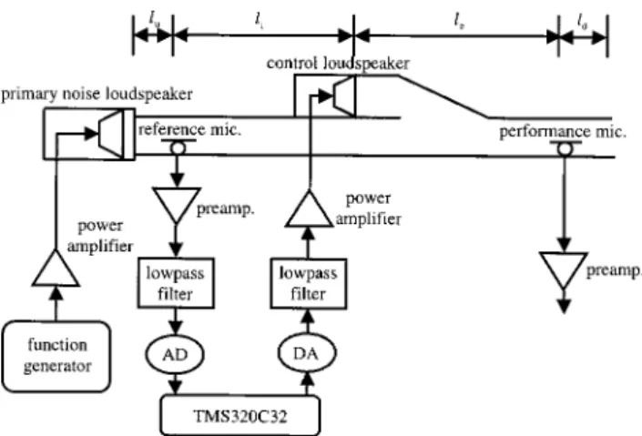
Figure 1共a兲 depicts a duct ANC system with spatially feedforward structure. In this structure, an upstream micro-phone is employed to measure the sound field near the pri-mary noise source. The signal from the upstream microphone is fed to the controller, which produces a control signal to drive a downstream control speaker that generates an anti-field to interact with the primary noise anti-field. The goal of active control is to minimize the residual noise downstream of the control speaker. The definitions of symbols can be found in the Nomenclature and Ref. 15.
Munjal and Eriksson16 derived the ideal controller ca-pable of achieving global noise cancellation downstream of the control source in a finite-length duct
C⫽⫺Zsa Y0
冉
e⫺ jkli
1⫺e⫺2 jkli
冊
⫽C0•Cr, 共1兲where Zsa is the equivalent acoustic impedance of the
con-trol source, Y0⫽c/S is the characteristic impedance of the duct, c is the sound speed, S is the cross-sectional area of the duct, k is the wave number, and liis the distance between the
upstream measurement microphone and the control source. In Eq. 共1兲, C0⬅⫺Zsa/Y0 is a function of the finite imped-ance Zsa, which depends only on the electro-mechanical
pa-rameters of the control source. On the other hand, Cr
⬅e⫺ jkli/1⫺e⫺2 jkli takes the form of the so-called repetitive
controller.17 Due to the infinite number of poles on the imaginary axis, both frequency response and impulse re-sponse of the ideal controller exhibit patterns of comb-typed periodic peaks (⌬ f ⫽c/2li,⌬t⫽2li/c). The fundamental
reason for the repetitiveness is essentially rooted in the acoustic feedback.
In the course of analysis, we shall develop some physi-cal insights into the causality of the ANC system by exam-ining the aforementioned ideal controller. It is observed from Eq. 共1兲 that the implementation of the ideal controller re-quires the knowledge of the control source impedance Zsa. In what follows, Zsa will be expressed explicitly in terms of the electro-mechanical parameters of speaker. Detailed analysis will show that Zsa can be expressed as15
Zsa⫽ 1 S2
冉
1 zM ⫹ B 2l2 R⫹ j⍀L冊
, 共2兲where R is the total equivalent resistance of the coil, L is the equivalent inductance of the coil, Bl is the coil constant, zM is the mechanical mobility, and⍀ is the analog frequency in rad/s. In the expression of Eq.共2兲, Zsadepends solely on the
speaker parameters R, L, and Bl that can be identified in advance.18 In the experimental setup in our case, these pa-rameters were identified and listed in Table I. With the trans-ducer dynamics taken into account, it has been shown in Ref. 15 that the resulting controller is
C
⬘
⫽⫺ 1 GXDCR冉
e⫺ jkli 1⫺e⫺2 jkli冊
, 共3兲 where GXDCR⫽共gpgmGs兲 Y0 Zsa 共4兲represents the overall transducer dynamics, where gpand gm denote the constant gains of the power amplifier and the microphone, respectively, and Gs is the frequency response function of the speaker
Gs⫽ Bl
S共R⫹ j⍀L兲. 共5兲
Inspection of Eq.共3兲 reveals that the transducer response must compete with the propagation delay e⫺ jkli in the
acous-tic path. More precisely, the condition under which the re-sulting controller is causal is that the term e⫺ jkli/G
XDCRmust be causal. This is an important causality constraint one must observe, particularly for the spatially feedforward structure.
Omitting the constants gp, gm, and Y0 in Eq. 共4兲, GXDCR can be written as a third-order system
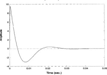
GXDCR⬃ 共BlRMCMs兲/关MMRMCMLs3 ⫹共CML⫹MMRMCMR兲s2
⫹共CMR⫹RML⫹B2l2RMCM兲s⫹RMR兴 , 共6兲 where MM, RM, CMare mechanical mass, viscous damping, and mechanical compliance, respectively. For example, we can use the data in Table I and plot the impulse response of GXDCR, as shown in Fig. 2. The first peak is at 0.3 ms, which amounts to 0.6 delay samples at 2-kHz sampling rate. Using this as a criterion of transducer delay, the length of the duct must be greater than 343 m/s 共at 20 °C兲 ⫻0.3 ms⫽0.103 m to meet the causality condition.
In addition to transducer delay, other types of electronic delay include all possible delays in the antialiasing/ smoothing filters 共denoted as ␦F兲, AD/DA conversion, and the one-sample processing time 共provided computations are completed within one sample兲, where the last two terms can be lumped into a single term␦T. These delays, together with the group delays of transducer and the digital controller 共de-noted as␦Xand␦W, respectively兲, constitute the total elec-tronic delay
␦E⫽␦X⫹␦F⫹␦T⫹␦W. 共7兲
The electronic delays are summarized in Fig. 3. The trans-ducer delay␦Xis estimated according to the first peak of the impulse response of Eq. 共6兲. The analog filter delay can be TABLE I. The electro-mechanical parameters of a moving-coil speaker.
Electro-mechanical constants MM 13.83 g RM 1.3 ohms CM 874m/N R 6.88 ohms L 0.68 mH Bl 4.85 T-m
estimated by␦F⫽n/8fc, where n is the filter order and fc is the cutoff frequency.19The one-sample delay and the AD/DA delay together can be estimated by ␦T⫽⌬⌽/360⌬ f , where ⌽ is the unwrapped phase 共in degrees兲 of the DSP frequency response in ‘‘echo’’ operation.
A formal statement of the causality constraint on the spatially feedforward ANC system can now be written as
␦A⭓␦E, 共8兲
where the acoustical delay ␦A⫽li/c, li being the distance
between the upstream microphone and the control speaker. Violation of the causality constraint, i.e., the electronic delay is greater than the acoustical delay, will result in a noncausal controller. An optimal causal approximation to a noncausal controller may well exist theoretically and converge to the Wiener filter solution.20 However, in practice, violation of causality would give rise to performance degradation of an ANC system, depending on the degree of violation. For the compensators to be implementable, the acausal part must be truncated to construct FIR filters. Physically, the causality constraint sets the minimum length of duct for which random noise can be effectively canceled
共li兲min⭓c␦E. 共9兲
Therefore, a system with large electronic delay will generally lead to impractical length of duct, especially when the sam-pling rate is low. For example, the samsam-pling rate is selected to be 2 kHz in our experiment, rendering an estimated elec-tronic delay of 4.3 samples. This corresponds to a minimal duct length of 73 cm. From the delay components listed in Table II, it can be observed that␦Fand ␦T contribute most significantly to the overall delay. Given a length limitation of a duct, one must strive to minimize the electronic delay in order to meet the causality constraint. To this end, a multirate signal-processing technique is developed in this work for reducing the delays␦Fand␦T.
III. MULTIRATE SIGNAL PROCESSING BY POLYPHASE FILTERS
To reduce electronic delay, this paper proposes a digital signal-processing scheme based on the multirate concept. In this approach, only inexpensive analog filters with high cut-off frequency, e.g., 8 kHz, are required. To enhance compu-tation efficiency, a polyphase method is employed in filter design. This technique reduces the delay in the control loop by increasing the sampling frequency of AD and DA con-verters and, at the same time, permits the low-frequency per-formance of the FIR filter to be improved.
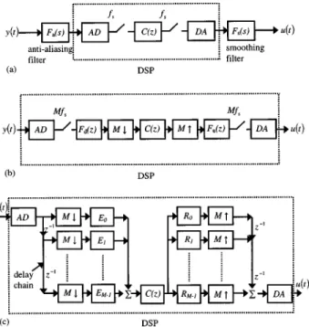
The block diagram of a conventional ANC system is depicted in Fig. 4共a兲. The system generally suffers from ex-cessive electronic delay, especially for low sampling rate and/or low filter cutoff frequencies. It may create a causality problem in the ANC system, particularly for the control of broadband random noise where upstream microphone spac-ing is limited, such as short ducts. It is then highly desirable to minimize, whenever possible, the group delay in the elec-tronic path. To this end, an ANC system based on multirate digital signal processing is developed in the work. The gen-eral idea of the multirate ANC system is depicted in Fig. 4共b兲. In the new structure, the sampling rate of AD and DA converters is raised to a much higher rate, say, M fs, with M being the decimation factor. The continuous-time signal y (t) from the sensor is discretized by an AD converter at a high sampling rate, filtered by a low-pass digital filter, and deci-mated by a downsampler. The signal is then processed by a low sampling rate ( fs) digital controller C(z) to produce an output signal that is in turn interpolated by an expander to the high sampling rate, M fs. In this paper, a fixed controller C(z) is synthesized for the spatially feedforward duct prob-lem. The frequency response samples of the controller are calculated by using Eq. 共3兲. Then, the discrete-time transfer
FIG. 3. The elements of electronic delay␦E.
TABLE II. The elements of electronic delay measured in samples 共on a 2-kHz basis兲. Delay elements Conventional implementation 共samples兲 Multirate implementation 共samples兲 ␦X 0.6 0.6 ␦F 2.2 0.3 a ␦T 1.5 0.7 Total delay 4.3 1.6
aIncludes the delay of digital LPF⫽0.1 samples.
FIG. 4. The structures of implementation for a duct ANC system.共a兲 The conventional structure;共b兲 the original multirate structure; 共c兲 the multirate structure using polyphase representation.
function of the controller C(z) is obtained simply by curve-fitting the frequency response samples, using the MATLAB command invfreqz. The details of implementation can be found in Ref. 15. The upsampled signal is low-pass filtered before DA conversion into the continuous-time actuating sig-nal u(t). It is noted that, in this multirate scheme, hardware complexity and the associated delay are reduced because pass filtering is all done by software and analog low-pass filters are no longer needed. Efficient implementation of the interpolation and decimation filters forms the basis of a delay-reduced ANC system. Optimization methods can be utilized to calculate the filter coefficients, as will be detailed in the next section. In addition to the reduction of hardware complexity, the AD/DA delay and the one-sample computa-tion delay are almost negligible because the critical processes are operated at a much higher sampling rate, hence the sav-ing of␦Tand␦F.
As a final touch, computation efficiency of the multirate ANC system can be drastically enhanced by polyphase fil-ters, as shown in Fig. 4共c兲, where the decimation factor M and the interpolation factor L are identical. Note that the decimation filter and the interpolation filter both contain de-lay chains that function essentially as rotating switches.7
IV. FILTER DESIGN BY FREQUENCY-DOMAIN OPTIMIZATION
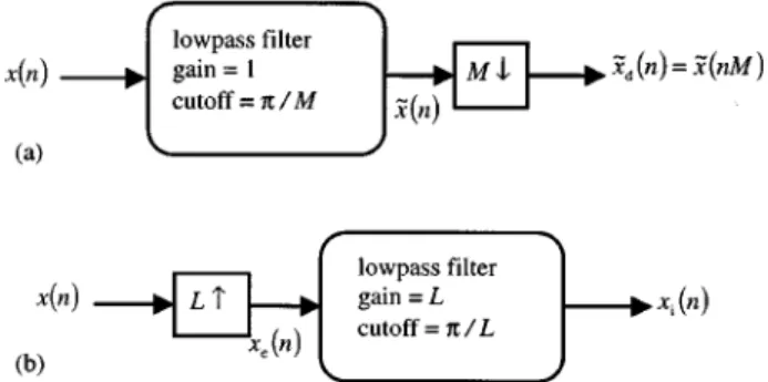
The decimation and interpolation processes in the fore-going multirate ANC system involve the design of two digi-tal low-pass filters. In order to avoid aliasing in downsam-pling by a factor of M, a low-pass filter is required with a cutoff frequency
N⬍/ M , 共10兲
as illustrated in Fig. 5共a兲. If the discrete-time input x(n) is filtered by such a filter, then the output x˜ (n) can be down-sampled without aliasing. Such a system is called a decima-tor. On the other hand, to reconstruct the sequence by upsam-pling with a factor of L requires another low-pass filter with cutoff frequency/L and gain L, as shown in Fig. 5共b兲. Such a system is called an interpolator. In general, FIR filters are employed as the low-pass filters due to the fact that they are inherently stable.
To further improve the computation efficiency, optimi-zation techniques11 in frequency domain are developed for
minimizing the filter length. In terms of H1, H2, and H⬁ norms, the optimization problem of the filter design can be written as follows:12 min h共k兲苸R
冐
k兺
⫽0 K⫺1 h共k兲e⫺ jk⫺Hd共ej兲冐
1,2,⬁ , 共11兲where储 储 denotes the norm, is the digital frequency, K is the tap length of the FIR filter, h(k) is the impulse response 共or the filter coefficients兲 of the FIR filter, and Hd(ej) is a low-pass frequency response template. The objective here is to find the filter coefficients h(k) such that the ‘‘difference’’ 共measured by 1, 2, or ⬁ norm兲 between the desired and the resulting frequency responses is minimized. Globally opti-mal solutions exist for these problems because they all fall into the class of convex problems.12,13
The optimization problem of Eq.共11兲 can now be solved numerically by subroutines fminu 共1 norm and 2 norm兲 and minimax 共⬁ norm兲 in the MATLAB optimization toolbox.13 Among these, the H2 optimization problem can also be solved via the least-square method. Express the desired fre-quency response into a FIR form
Hd共z兲⫽
兺
k⫽0 K⫺1
h共k兲z⫺k. 共12兲
Substituting the frequency samples z⫽ejn, n⫽1,2,...,N, in
Eq. 共12兲 leads to the following linear system of equations:
冋
Hd共ei1兲 Hd共ei2兲 ] Hd共eiN兲册
⫽冋
e⫺ j1⫻0 e⫺ j1⫻1 ¯ e⫺ j1⫻共K⫺1兲 e⫺ j2⫻0 e⫺ j2⫻共K⫺1兲 ] ] e⫺ jN⫻0 e⫺ jN⫻1 ¯ e⫺ jN⫻共K⫺1兲册
⫻冋
H共0兲 h共1兲 ] h共K⫺1兲册
. 共13兲In matrix notation, Eq.共13兲 can be written in a more compact form
b⫽Ax. 共14兲
The least-square solution of Eq. 共14兲, corresponding to the H2 optimization of Eq.共11兲, simply reads
x⫽A⫹b, 共15兲
where A⫹⫽(AHA)⫺1, AHb being the pseudoinverse21of A. To end this section, an important point regarding how to choose the desired filter response for multirate implementa-tion needs to be addressed. A common practice in multirate signal processing is to employ low-pass filters with linear phase property, where waveform distortion is the only con-cern. Unfortunately, such an approach did not work for our ANC application because of the undesired group delay
intro-FIG. 5. The decimator and the interpolator.共a兲 Decimator for sampling rate reduced by a factor M;共b兲 interpolator for sampling rate increased by a factor L.
duced by the filters. Instead, we selected the templates Hd with minimal phase shifts within the passband. The best compromise between the stopband roll-off rate and the pass-band phase shift must be sought to choose the template. If there is not enough stopband roll-off, an aliasing problem will arise. On the other hand, increasing the filter roll-off will increase phase shift and degrade the performance. Once an appropriate template is chosen, it can be amended to the aforementioned optimal filter design procedure.
The model-matching criterion described in Eq.共11兲 is a general-purpose frequency-domain FIR filter design method. It is a simple technique that enables one to find the filter coefficients in an optimal fashion, given the frequency re-sponse specification. Different from FFT-based methods, this approach does not require the numbers of frequency samples and filter coefficients to be equal 共we generally want the latter as small as possible兲. In this work, the frequency-domain optimization technique is employed to design both the low-pass filters required in decimation and interpolation processes, and the ANC filter C(z) as well. That is, the filter template Hd can be low-pass filters or C(z), depending on what one is after.
An example of the optimal filter design is shown in Fig. 6. From the results, it can be observed that the H2 and H⬁ filters have similar trends in both frequency response and
impulse response. The filter obtained from H1 optimization has larger phase shift at high frequency than the other filters.
V. EXPERIMENTAL INVESTIGATIONS
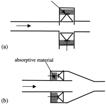
Experiments were undertaken to compare the perfor-mance of spatially feedforward duct ANC systems with and without multirate implementation. In addition, the effects of different optimal filter designs on the control performance are also examined. A wooden duct of length 440 cm and cross section 25⫻25 cm was constructed for the experi-ments. If the control loudspeaker is oriented like Fig. 7共a兲, the controller frequency response is expressed as Eq. 共3兲, in which an infinite number of poles will be present on the imaginary axis as a result of acoustic feedback. To mitigate the acoustic feedback, we faced the control loudspeaker to-wards the opening of the duct, as shown in Fig. 7共b兲. A practical loudspeaker differs from an ideal one-dimensional omnidirectional point source. In this configuration, Eq. 共3兲 should be modified into
C
⬘
⫽⫺ 1GXDCR
冉
e⫺ jkli
1⫺De⫺2 jkli
冊
, 共16兲where兩D兩⬍1 signifying the ‘‘directivity factor’’ of the trans-ducer, which is generally frequency dependent with increas-ing attenuation as frequency is increased. Such an approach would effectively reduce the repetitiveness of the controller impulse response 共because the poles are moved away from the imaginary axis兲 and improve the performance as well. An extensive investigation on this technique can be found in Ref. 22. A TMS320C32 DSP equipped with four 16-bit ana-log IO channels is utilized to implement the controller. The sampling frequency is chosen to be 16 kHz. The up/down sampling factor is selected to be 8, rendering a nominal sam-pling rate of 2 kHz for the digital controller C(z).
Consid-FIG. 6. Comparison of optimal filter designs using H1, H2, H⬁ norms, respectively.共a兲 The frequency responses; 共b兲 the impulse responses. tem-plate共—兲, 1-norm 共–•–兲, 2-norm 共¯兲, ⬁-norm 共––兲.
FIG. 7. Two arrangements of control loudspeaker.共a兲 Sideway loudspeaker; 共b兲 backward loudspeaker.
ering the cutoff frequency of the duct 共approximately 700 Hz兲 and the poor response of the control speaker at low frequency, we chose as the control bandwidth 200 to 600 Hz. It is noted that the delays introduced by the multirate low-pass filters have been compensated by a simple ‘‘preview’’ procedure15 in implementing C(z) as follows:
共a兲 Measure the frequency response of the DSP in the ‘‘echo’’ mode共with only AD/DA conversions and the multirate filters兲, and estimate the effective delay 共in samples兲 by N⫽⌬⌽/360T⌬ f , where f is frequency 共in Hz兲, ⌽ is the unwrapped phase 共in degrees兲, and T is the sampling period.
共b兲 Compensate the controller C(z) by multiplying its fre-quency response with exp(jN).
共c兲 Calculate the discrete-time transfer function of the compensated controller by using theMATLABcommand invfreqz. This would effectively ‘‘phase-lead’’ compen-sate the controller by a phase shiftf⌬⌽/180⌬ f . It is also tantamount to advancing the impulse response of the controller; hence the name preview.
The active noise controller of Eq.共3兲 was implemented on the platform of the above-mentioned hardware system. The distance between the upstream measurement micro-phone and the control speaker is 2.8 m to avoid any causality problem.
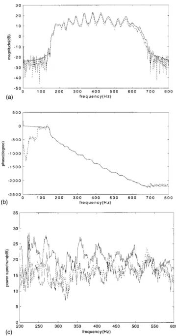
In order to examine if the multirate approach is an ef-fective method for designing low-speed digital filters in junction with high-speed IO channels, an experiment is con-ducted for comparing the conventional low sampling rate method and multirate rate method with H2 optimal filter. Figure 8共a兲 shows the experimental results obtained from DSP implementation of both methods. Good agreement can be found in the magnitude response within the control band-width 200– 600 Hz. However, the phase response deserves more explanation. At low sampling rate共2 kHz兲, the IO de-lay (␦T) of the conventional implementation is approxi-mately 1.5 samples. The controller must be advanced using samples previewed by 1.5 to compensate for the delay. By multirate implementation, where the sampling rate is raised to 16 kHz, the IO delay can be reduced to only 0.7 samples 共on a 2-kHz basis兲. The controller is then previewed by 0.7 samples to compensate for the delay. These two compensated phase responses are shown in Fig. 8共b兲. Good agreement can be seen in the phase response within the control bandwidth 200– 600 Hz, while the discrepancy below 200 Hz could be due to the poor signal-to-noise ratio outside the band.
An experiment is then undertaken to compare various optimal filter designs used in multirate implementation 共16 kHz兲. The result of the conventional low sampling rate implementation 共2 kHz兲 is also included for reference. Broadband random noise is used as the primary noise. Vari-ous systems are implemented by this scenario: the first case is the conventional ANC without multirate implementation, while the next three cases are multirate ANC with H1, H2, H⬁ optimal filters, respectively. The experimental results are shown in Fig. 8共c兲. Significant attenuation of noise has been obtained throughout the control bandwidth. The results are also summarized in Table III. Note that the delays introduced
by the multirate low-pass filters have been compensated by the preview procedure in implementing C(z) that are opti-mally designed for each test case in the table. As indicated in the results, the multirate approach is able to provide better performance with less hardware complexity than the
conven-FIG. 8. The experimental results of comparison of ANC systems with and without multirate approach, using H2 optimal filter.共a兲 The magnitude
re-sponses of controller;共b兲 the phase responses of controller 关without multi-rate共———兲; with multirate 共¯兲兴; 共c兲 the ANC performance 关control off
共—兲; control on, without multirate 共¯兲; control on, with multirate 共––兲兴.
TABLE III. Summary of ANC performance for conventional and multirate implementations (li⫽2.8 m). Method Sampling rate 共kHz兲 IO delay on DSP共2 kHz兲 共samples兲 Maximum attenuation 共dB兲 Total attenuation 共dB兲 Conventional 2 1.5 15.3 7.4 Multirate H1 16 0.4 16.8 6.6 Multirate H2 16 0.7 17.1 7.6 Multirate H⬁ 16 0.7 15.2 7.3
tional implementation. The multirate structure based on the polyphase representation achieves not only reduction of elec-tronic delay but also enhancement of performance of the ANC controller. In particular, the multirate ANC with H2 optimal filter appears to yield the best performance 共total attenuation 4.8 dB and maximum attenuation 17.3 dB兲. Thus, in the next experiment, we shall focus our discussion only on the multirate ANC with H2 optimal filter.
At this point, one question will naturally arise. What is the limit of shortest length that one is able to achieve by using the multirate approach in the spatially feedforward duct ANC system? On the basis of the delay estimation pro-cedure depicted in Fig. 3, the total electronic delay is esti-mated as 1.6 samples共with details presented in Table II兲. To ensure a causal controller, this in turn renders the minimal length li⫽23 cm, which is a remarkable improvement owing
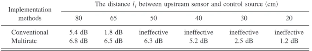
to the considerable reduction in the analog filter delay and digital IO delay. To justify the above theoretical prediction, the experiment is repeated for li⫽80, 65, 50, 40, 30, and 20
cm, respectively. The results are summarized in Table IV. Both the conventional approach and multirate approach with the H2 optimal filter have produced attenuation for li⫽80
and 65 cm. However, for shorter lengths the conventional method begins to lose performance, whereas the multirate method remains effective in achieving broadband attenua-tion, as shown in Fig. 9. The word ‘‘ineffective’’ in the table refers to the case where no attenuation was observed in the experiment. For brevity, only the results for li⫽50 and 20
cm are shown. As expected, the performance deteriorates with decreasing length.
VI. CONCLUSIONS
This paper suggests three potential contributions. First, this work represents the first application of a multirate ANC system to duct problems. Second, the significance of delay to the spatially feedforward system with strong acoustic feed-back is thoroughly examined in the paper. Third, details of how one should implement the multirate scheme in the con-text of ANC applications are presented, and how effective the approach would be with regard to physical dimension is quantitatively evaluated. A detailed analysis of causality for spatially feedforward ANC systems reveals that electronic delay dictates the minimal upstream measurement micro-phone spacing li. A multirate approach has been developed in this work for reducing the electronic delay in the control loop. Analog low-pass filters were replaced by direct deci-mation and interpolation, through the use of digital filters. The computation efficiency is further enhanced by a polyphase representation, where the phases of low-pass fil-ters must be carefully designed to avoid unnecessary delays. Frequency domain optimization procedures based on H1, H2, and H⬁norms, respectively, are utilized to facilitate the FIR filter design. Experimental results demonstrated the ef-fectiveness of the multirate approach in suppressing a broad-band random noise in a spatially feedforward duct ANC sys-tem. In particular, the H2 design yielded the best results because it has the smallest phase shift in low-pass filtering.
However, some possibilities remain for improvement of the proposed techniques. For instance, better FIR filter de-sign should be sought, concentrating on the vicinity of cutoff where distortions are likely to arise. The up/down sampling factor共currently 8兲 should be increased to further reduce the delay. The active controller was implemented as a fixed digi-tal filter in this paper. However, in an adaptive system, this multirate technique can be highly useful. On the basis of this work, these aspects shall be explored in the future research.
ACKNOWLEDGMENTS
The work was supported by the National Science Coun-cil in Taiwan, Republic of China, under the Project Number NSC 89-2212-E-009-007. The authors also thank the techni-cal editor, Dr. M. Stinson, for providing the faxed copy of Ref. 14.
1
S. J. Elliott and P. A. Nelson, ‘‘Active noise control,’’ IEEE Signal Pro-cess. Mag. 10, 12–35共1993兲.
2R. F. La. Fontaine and I. C. Shepherd, ‘‘An experimental study of a
broad-band active attenuator for cancellation of random noise in ducts,’’ J. Sound Vib. 91, 351–362共1983兲.
3M. A. Swinbanks, ‘‘The active control of sound propagation in long
ducts,’’ J. Sound Vib. 27, 411– 436共1973兲. TABLE IV. Attenuation versus distance lifor conventional and multirate implementations using H2filter. The
word ‘‘ineffective’’ in the table refers to the case where no attenuation was observed in the experiment.
Implementation methods
The distance libetween upstream sensor and control source共cm兲
80 65 50 40 30 20
Conventional 5.4 dB 1.8 dB ineffective ineffective ineffective ineffective
Multirate 6.8 dB 6.5 dB 6.3 dB 5.2 dB 2.5 dB 1.2 dB
FIG. 9. The experimental results of ANC performance for li⫽20 and 50 cm,
using multirate implementation with H2optimal filter. control off共—兲, on
4S. M. Kuo and D. R. Morgan, Active Noise Control Systems: Algorithms and DSP Implementations共Wiley, New York, 1995兲.
5J. C. Doyle, B. A. Francis, and A. R. Tannenbaum, Feedback Control Theory共Macmillan, New York, 1992兲.
6R. E. Crochiere and L. R. Rabiner, Multirate Digital Signal Processing 共Prentice-Hall, Englewood Cliffs, NJ, 1983兲.
7P. P. Vaidyanathan, Multirate Systems and Filter Banks 共Prentice-Hall,
Englewood Cliffs, NJ, 1993兲.
8
P. P. Vaidyanathan, ‘‘Design and implementation of digital FIR filters,’’ in Handbook on Digital Signal Processing, edited by D. F. Elliott 共Aca-demic, Cambridge, UK, 1987兲, pp. 55–172.
9M. Bellanger, G. Bonnerot, and M. Coudreuse, ‘‘Digital filtering by
polyphase network: Application to sample rate alteration and filter banks,’’ IEEE Trans. Acoust., Speech, Signal Process. ASSP-24, 109–114共1976兲.
10P. P. Vaidyanathan and V. C. Liu, ‘‘Classical sampling theorems in the
context of multirate and polyphase digital filter bank structures,’’ IEEE Trans. Acoust., Speech, Signal Process. ASSP-36, 1480–1495共1988兲.
11
J. S. Arora, Introduction to Optimum Design共McGraw-Hill, New York, 1989兲.
12S. Boyd, L. Vandenberghe, and M. Grant, ‘‘Efficient convex optimization
for engineering design,’’ in Proceedings of the IFAC Symp. Robust Contr. Design, Rio de Janeiro, Brazil, Sept. 1994.
13
A. Grace,MATLABoptimization toolbox共The Mathworks, 1995兲.
14A. J. Brammer, G. J. Pan, and R. B. Crabtree, ‘‘Adaptive feedforward
active noise reduction headset for low-frequency noise,’’ Proceedings ACTIVE 97共Budapest, Hungary, August, 1997兲.
15
M. R. Bai, Y. J. Lin, and J. D. Wu, ‘‘Analysis and DSP implementation of a broadband duct ANC system using spatially feedforward structure,’’ ASME J. Vibr. Acoust. 123, 129–136共2001兲.
16M. L. Munjal and L. J. Eriksson, ‘‘An analytical, one-dimensional,
standing-wave model of a linear active noise control system in a duct,’’ J. Acoust. Soc. Am. 84, 1086 –1093共1988兲.
17M. T. S. Tomizuka and K. K. Chew, ‘‘Analysis and synthesis of
discrete-time repetitive controllers,’’ ASME J. Dyn. Syst., Meas., Control 111, 353–358共1989兲.
18
R. H. Small, ‘‘Closed-box loudspeaker systems. I. Analysis,’’ J. Audio Eng. Soc. 20, 798 – 808共1972兲.
19P. A. Nelson and S. J. Elliott, Active Control of Sound共Academic, San
Diego, 1992兲.
20R. A. Burdisso and C. R. Fuller, ‘‘Causality analysis of feedforward
con-trolled systems,’’ J. Acoust. Soc. Am. 94, 234 –242共1993兲.
21B. Noble, Applied Linear Algebra共Prentice-Hall, Englewood Cliffs, NJ,
1969兲.
22J. D. Wu and M. R. Bai, ‘‘Effects of directional microphone and
trans-ducer in spatially feedforward active noise control system,’’ Jpn. J. Appl. Phys. 40, 6133– 6137共2001兲.