國 立 交 通 大 學
電信工程學系
碩 士 論 文
A Reliable Routing Algorithm for Mobile
Ad-Hoc Networks
對於移動式隨建即連網路的一種可靠路由
方法
研究生:趙偉臣
指導教授:李程輝 博士
中 華 民 國 94 年 6 月
對於隨建即連網路的一種可靠路由方法
A Reliable Routing Algorithm for Mobile
Ad-Hoc Networks
研 究 生: 趙偉臣
Student: Wei-Chen Chao
指導教授: 李程輝 博士
Advisor: Prof. Tsern-Huei Lee
國 立 交 通 大 學
電 信 工 程 學 系
碩 士 論 文
A Thesis
Submitted to Institute of Communication Engineering College of Electrical Engineering and Computer Science
National Chiao Tung University in Partial Fulfillment of the Requirements
for the Degree of Master of Science
in
Communication Engineering June 2005
Hsinchu, Taiwan, Republic of China.
對於隨建即連網路的一種安全路由方法
研究生: 趙偉臣
指導教授: 李程輝 教授
國立交通大學
電信工程學系碩士班
中文摘要
隨建即連的網路是由一群行動主機自我組織起來的網路,和傳統的移動無線 網路不同的地方在於隨建即連的網路不需要依靠一些固定的基礎設施,例如基地台(Base station)以及接取點(Access point),他們的通訊方式是藉由中間節點
的轉送,以多點跳躍(multi-hop)的方式來完成,由於不受那些基礎設施的限制, 所以移動性高,而且部署非常容易。由於這些主機會一直移動,造成整個網路的 拓樸不斷的改變,所以必須要有一種快速的方法來偵測目前的拓樸(topology) 情況,當使用中的路徑中斷時,才能夠迅速的尋找到另外一條路徑來繼續傳送。 在無線網路中,安全性是一個很重要的關鍵,由於在一個無線的環境下傳送資料 是非常不可靠的,所以安全性也必須要考慮進去。我們研究了許多種路由的方法 以及增加安全性的方法,由於我們的目標是希望整個方法是能夠迅速以及簡單, 所以我們提出了一個方法,使得尋找路徑加上增加安全性能夠用一個簡單的方法 來實現。
A Reliable Routing Algorithm for Mobile Ad-Hoc
Networks
Student: Wei-Chen Chao
Advisor: Prof. Tsern-Huei Lee
Institute of Communication Engineering
National Chiao-Tung University
Abstract
An ad hoc network is a network composed by a group of mobile hosts. Unlike
traditional mobile wireless networks, ad hoc networks do not rely on any fixed
infrastructure such as base stations and access points. These mobile hosts complete
their transmission by transferring the data by intermediate nodes and send the data by
multi-hop. Because ad hoc networks do not limit to the infrastructure, they have high
mobility and they can be built easily. Because these hosts move, the topology of the
network will always change. We have to use an algorithm to detect the topology fast.
When some links are broken, we can find another path to keep transmitting the data as
fast as possible. In wireless networks, security is a very important issue. Data
transmission is vulnerable in the wireless surrounding, so we have to consider the
security. There are many proposed routing methods and many ways to enhance the
security. Because our goal is how to find another route to keep transmission when
some links are broken and enhance the security easily, our proposed algorithm which
combines the redundancy base multi-path routing protocol and the Diffie-Hellman key
誌 謝
特別感謝我的指導教授—李程輝教授,在這碩士班的兩年之中所給予我的指 導、鼓勵以及協助,提供許多寶貴的意見,使得碩士班的兩年生活感到非常充實, 而且才能讓我能夠順利的完成這個論文,在此,向我的指導教授致上最深的感謝。 感謝網路技術實驗室的學長們:德功、震榮學長,給我的指導,也感謝實驗 室的同學們:易霖、孟諭、冠亨、怡彣、景融、偉志、偉倫、文彬、名駿、謹慧 和雅婷,這兩年來在實驗室裡互相的討論研究,不只是在學業的方面,在生活上 大家也相處的非常融洽,讓我這兩年過得非常愉快,也充滿了回憶。 感謝我的父親趙榮宗先生以及母親莊燊銀小姐,從小到大對我的教育以及栽 培,無私的付出,才能讓我無後顧之憂完成論文。 僅以本論文獻給我愛的家人以及朋友。 2005.6 新竹交大Contents
Contents
English Abstract i 中文摘要 ii 誌謝 iii Contents iv List of Tables v List of Figures vi Chap 1 Introduction 1 1.1 Background...……….………... 1 1.2 Security goals……….………..……… 3 1.3 Related works………... 41.4 Organization of the thesis……….. 6
Chap 2 Some routing protocols for ad hoc networks 7 2.1 Proactive (table-driven) routing protocols………... 7
2.2 Reactive (on-demand) routing protocol………... 10
2.2.1 DSR (Dynamic Source Routing)………... 10
2.2.1.1 Route Discovery………..
2.2.1.2 Route Maintenance……….. 11
2.2.2 AODV (Ad Hoc On-Demand Distance-Vector) protocol...
2.2.2.1 Route Discovery………..
2.2.2.2 Forward path setup………..
2.2.2.3 Route Maintenance……….. 13
13
15
17
2.3 Hybrid Routing Protocol………... 19
Chap 3 Some security mechanisms 20
3.1 Key management……... 20
3.1.1 Public announcement of public keys………... 20
3.1.2 Public-key authority………... 3.1.3 Public-key certificates……….. 21 22 3.2 Diffie-Hellman key exchange………... 25
3.3 Summary………... 28
Chap 4 Proposed secure routing protocol for mobile ad hoc networks (MANETs) 29 4.1 Redundancy Based Multi-path Routing protocol…………... 29
4.1.1 Path redundancy………..……... 29
4.1.2 Route establishment…….……... 30
4.1.3 Route setup process………..………... 30
4.1.4 Route reply process………..
4.1.5 Route reconfiguration………... 32
Contents
4.1.5.1 Failure notification………..
4.1.5.2 Find an alternate path………..
4.1.6 RBMR compares with DSDV and AODV………... 36
36
37
4.2 RBMR with Diffie-Hellman key exchange algorithm……….. 38
Chap 5 Conclusions 42
List of Tables
2.1 MH4 advertised routing table……….. 9
2.2 MH4 advertised routing table (updated) ………..….……. 10
4.1 Route request packet format …..……… 39
4.2 Route reply packet format ………. 40
List of Figures
List of Figures
1.1 Topology changes in ad hoc networks ………... 2
2.1 DSDV (Destination-Sequenced Distance-Vector)……….…. 8
2.2 The movement of MH1………..……. 9
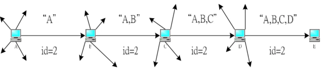
2.3 Route discovery example with node A as initiator and node E as the target ………...……. 12
2.4 Route maintenance example (Node C is unable to forward a packet from A to E over its link to the next hop, D.)………... 13
2.5 Propagation of RREQ throughout the network……… 15
2.6 Route determination from source to destination... 17
2.7 Route maintenance……….……….. 19
3.1 Uncontrolled public-key distribution………..… 21
3.2 Public-key distribution scenario………...………... 24
3.3 Exchange of Public-key certificates……….... 24
3.4 The Diffie-Hellman Key Exchange Algorithm………... 26
3.5 Diffie-Hellman Key Exchange……… 28
4.1 The route setup packet flooding……….…….... 32
4.3 End-to-End delay………... 37
4.4 Packet delivery ratio………...………. 38
Chapter 1 Introduction
Chapter 1
Introduction
1.1 Background
As wireless network nodes proliferate and as applications using the Internet
become familiar to a wider class of customers, those customers will expect to use
networking applications even in situations where the Internet itself is not available.
For example, people using laptop computers at a conference in a hotel might wish to
communicate in a variety of ways, without the mediation of routing across the global
Internet. Yet today such obvious communications requirements can not be easily met
using Internet protocols. The proposals to be described allow mobile computer users
with wireless communication devices to set up a possibly short-lived network just for
the communication needs of the moment – in other words, an ad hoc network.
Ad hoc networks are a paradigm of wireless communication for mobile hosts
(which we call nodes). In an ad hoc network, there is no fixed infrastructure such as
base stations or mobile switching centers. Mobile nodes within each other’s radio
range communicate directly via wireless links, while those that are far apart rely on
other nodes to relay messages as routers. Node mobility in an ad hoc network causes
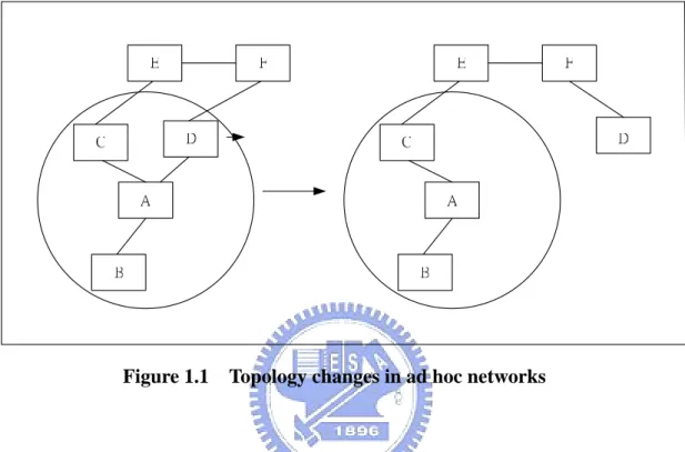
A and D have a direct link between them. When D moves out of A’s radio range, the
link is broken. However, the network is still connected, because A can reach D
through C, E and F.
Figure 1.1 Topology changes in ad hoc networks
In ad hoc networks, all the transmission is wireless. The security is an important
issue for ad hoc networks, especially for security-sensitive applications. A mobile ad
hoc network is a collection of wireless mobile nodes that are capable of
communicating with each other without the use of network infrastructure or any
centralized administration. One main challenge in the design of this network is its
vulnerability to security attacks. Ad hoc network is vulnerable to the same kind of
attacks present in the wired network. The attack presents in the wired network can be
easily overcome by using security mechanisms such as encryption to provide
confidentiality, authentication, digital signature, integrity, non-repudiation etc.
However, these services will be effective only when secret keys are shared among
nodes. This requires centralize key management and distribution algorithms, which is
Chapter 1 Introduction
Secure routing and intrusion detection is easier in a wired network because of its
steady network topology, which enables static routing and dedicated router. Wired
network routers also have more bandwidth and CPU power. So encryption,
authentication and digital signature are easily incorporated at every node without
power and bandwidth constraints. But in an ad hoc network, each node acts as a router
and there is restriction on power consumption. This prevents the usage of complex
encryption algorithm.
In the wired network it is easier to establish a trust relationship among the
hierarchical infrastructure. In an ad hoc network establishing a trust relationship is
quite hard because of its self-organizing nature and mobility. In any wireless network,
messages can be eavesdropped without physical access to the network components.
Thus securing an ad hoc network is a challenging task.
The security of the data transmission is important and we know that in an ad hoc
network key distribution is not easy. So in this thesis, we find a easy way to encrypt
the data and ensure that the data will not be eavesdropped.
1.2 Security goals
In [1] Zhou and Hass provide five security goals. To secure ad hoc networks,
we have to consider the following attributes: availability, confidentiality, integrity,
authentication, and nonrepudiation.
Availability ensures the survivability of network services despite
denial-of-service attacks. A denial-of-service attack could be launched at any layer
of an ad hoc network. On the physical and media access control layers, an
channels. On the network layer, an adversary could disrupt the routing protocol and
disconnect the network.
Confidentiality ensures that certain information is never disclosed to
unauthorized entities. Network transmission of sensitive information, such as
strategic or tactical military information, requires confidentiality. Leakage of such
information to enemies could have devastating consequences. Routing information
must also remain confidential in certain cases because the information might be
valuable for enemies to identify and locate their targets in a battlefield.
Integrity guarantees that a message being transferred is never corrupted. A
message could be corrupted because of transmission failures, such as radio
propagation impairment, or because of malicious attacks on the network.
Authentication enables a node to ensure the identity of the peer node with
which it is communicating. Without authentication, an adversary could masquerade
as a node, thus gaining unauthorized access to resource and sensitive information
and interfering with the operation of other nodes.
Finally, nonrepudiation ensures that the origin of a message can not deny
having sent the message. Nonrepudiation is useful for detection and isolation of
compromised nodes. When node A receives an erroneous message from node B,
nonrepudiation allows A to accuse B using this message and to convince other
nodes that B is compromised
1.3 Related work
Attacks in an ad hoc network vary from passive eavesdropping to active denial
Chapter 1 Introduction
these issues. Zhou and Hass [1] have used threshold cryptography to provide secure
routing and to establish secure key management service. However, a dealer should
be present to issue the global secret key. This increases the complexity and
vulnerability.
Marti [2] has used a different approach wherein extra facilities are installed in
the network to detect and mitigate routing misbehavior with the help of watchdogs
and path raters. Packets being forwarded by the intermediate node will be stored in
its buffer. With the help of this, the intermediate node monitors whether the
downstream node forwards the packet without any modification. This consumes
more memory and increases the computation demands at the intermediate node.
Further, if the intermediate node moves due to mobility, then there will be no
watchdog to monitor forwarding or modification of packets.
Dahill [3] has proposed authenticated routing for ad hoc networks where it
requires a trusted certification authority, Every node that forwards a route request
or a route reply must also sign it. This process increases the computation and
routing overhead.
Papadimitrators and Hass [4] have proposed a secure routing protocol (SRP).
This provides secure routing but relies on network geometry, which is not suitable
for an ad hoc network. In SRP, there is a pre-association of a secret key between the
source and destination nodes, which is applied for transmitting the routing packets.
Perlman studies how to protect routing information from compromised routers
in the context of Byzantine robustness [5]. The study analyzes the theoretical
feasibility of maintaining network connectivity under such assumptions. Kumar
recognizes the problem of compromised routers as a hard problem, but provides no
solution [6]. Other works [7,8,9] give only partial solutions. The basic idea
and to isolate compromised routers.
1.3 Organization of the Thesis
The rest of this thesis is organized as follows. In Chapter 2, we will see some
routing protocol for ad hoc networks. Chapter 3 will introduce some security
mechanisms. Our proposed approach will be in Chapter 4. Finally we will give a
Chapter 2 Some routing protocols for ad hoc networks
Chapter 2
Some routing protocols for ad hoc networks
There are many routing protocols in mobile ad hoc networks (MANETs). These
protocols mainly can be classified into three categories: Proactive (table driven)
routing protocols, Reactive (on-demand) routing protocols, and Hybrid routing
protocols.
2.1 Proactive (table-driven) routing protocols
In proactive (table-driven) routing protocols the mobile hosts (MHs) update
and exchange routing information (routing tables) with their neighbors periodically or
whenever the network topology has changed. Therefore, every MH can know the
topology of the whole network. Once a host wants to communicate with the other host,
it looks up the entry of the routing table and sends the data to the next hop
immediately. In table driven routing protocols, every host have to maintain one or
more routing table to keep the information of the topology of the network. Hence, the
exhaustion of resource in proactive routing protocols is higher than other routing
protocols.
DSDV (Destination-Sequenced Distance-Vector) [10] routing protocol is a
table-driven algorithm. DSDV extends the basic Bellman-Ford mechanism by
This destination sequence number is used to determine the “freshness” of a route.
Every node in the MANETs maintain a routing table containing the distances from
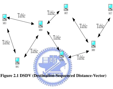
itself to possible destinations. Figure 2.1 shows that each mobile host exchanges the
routing table periodically by means of broadcasting even though the node does not
want to transmit data.
Figure 2.1 DSDV (Destination-Sequenced Distance-Vector)
The entry in the routing table contains the address of the destination node, the
address of the next hop, a sequence number and the metric (the number of hops
required to reach the destination node). The sequence number is tagged by the
destination node and it can make loop free and keep the freshness of the routing
information. Routes with more recent sequence numbers are preferred for making
packet forwarding decisions by a host. For routes with the equal sequence number, the
one with the smallest distance metric is chosen. Each time a host sends an update to
its neighbors, its current sequence number is incremented and included in the update.
The metric (hop count) field will be set ∞ when the node detects a broken link to the next hop and broadcasts the information. Any node that receive the information with
Chapter 2 Some routing protocols for ad hoc networks
∞ hop count and have an equal or later sequence number with a finite hop count value will disseminate the unreachable information about that destination node.
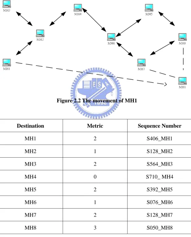
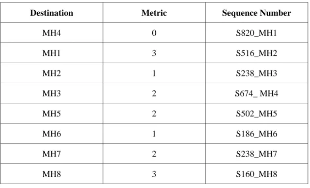
Figure 2.2 shows the example of DSDV topology movement and Table 2.1 shows the
routing table of MH4 before the movement of MH1 and Table 2.2 shows the updated
routing table of MH4 after the movement.
Figure 2.2 The movement of MH1
Destination Metric Sequence Number
MH1 2 S406_MH1 MH2 1 S128_MH2 MH3 2 S564_MH3 MH4 0 S710_ MH4 MH5 2 S392_MH5 MH6 1 S076_MH6 MH7 2 S128_MH7 MH8 3 S050_MH8
Destination Metric Sequence Number MH4 0 S820_MH1 MH1 3 S516_MH2 MH2 1 S238_MH3 MH3 2 S674_ MH4 MH5 2 S502_MH5 MH6 1 S186_MH6 MH7 2 S238_MH7 MH8 3 S160_MH8
Table 2.2 MH4 advertised routing table (Updated)
2.2 Reactive (on-demand) routing protocol
In reactive (on-demand) routing protocol [11, 12, 13, 14], a source node finds the
new route to transmit data by sending the RREQ (Route Request) packet. When the
destination receives the RREQ packet, it will reply a RREP (Route Reply) packet to
the source node. After receiving the RREP packet, source node begin to communicate
with the destination node. Therefore, MHs do not have to exchange their routing table
periodically when they do not want to communicate with the other node even if the
MHs have moved. In this way, there are no extra overheads when the topology has
changed.
2.2.1 DSR (Dynamic Source Routing)
DSR [15] is based on the on-demand source routing concept. One of the primary
Chapter 2 Some routing protocols for ad hoc networks
that carry the complete path from the source to the destination.
2.2.1.1 Route Discovery
When some node S originates a new packet destined for some node D, it places
in the header of the packet a source route giving the sequence of hops that the packet
should follow. Normally, S obtains a suitable source route by searching its route cache
of routes previously learned, but if no route is found in its cache it initiates the route
discovery protocol to find a new route to D dynamically. In this case, we call S the
initiator and D the target of the route discovery.
Figure 2.3 illustrates an example route discovery, in which node A is attempting
to discover a route to E. To initiate the route discovery, A transmits a RREQ (Route
Request) message as a single local broadcast packet, which is received by all nodes
currently within wireless transmission range of A. Each RREQ packet identifies the
initiator and target of the route discovery and also contains a unique request ID,
determined by the initiator of the request. Each RREQ also contains a record listing
the address of each intermediate node through which this particular copy of the RREQ
message has been forwarded. This route record is initialized to an empty list by the
initiator of the route discovery.
When another node receives a RREQ, if it is the target of the route discovery it
returns a RREP (Route Reply) message to the route discovery initiator, giving a copy
of the accumulated route record from the RREQ; when the initiator receives this
RREP, it caches this route in its route cache for use in sending subsequent packets to
the destination. Otherwise, if the node receiving the RREQ recently saw another
RREQ message from this initiator bearing this same request ID, or if it finds that its
own address is already listed in the route record in the RREQ message, it discards the
message and propagates it by transmitting it as a local broadcast packet (with the
same request ID).
In returning the RREP to the route discovery initiator, such as node E replying to
A in Figure 2.3, node E simply reverse the sequence of hops in the route record.
Figure 2.3 Route discovery example with node A as the initiator and node E as the target.
2.2.1.2 Route Maintenance
When originating or forwarding a packet using a source route, each node
transmitting the packet is responsible for confirming that the packet has been received
by the next hop along the source route; the packet is re-transmitted (up to maximum
number of attempts) until this confirmation of receipt is received. For example, in the
situation illustrated in Figure 2.4, node A has originated a packet for E using a source
route through intermediate nodes B, C, and D. If the packet is retransmitted by some
hop the maximum number of times and no receipt confirmation is received, this node
returns a RERR (Route Error) message to the original sender of the packet. For
example, in Figure 2.4, if C is unable to deliver the packet to the next hop D, C
returns a RERR to A, stating that the link from C to D is currently broken. Node A
then removes this broken link from its cache, and any retransmission of the original
packet is a function for upper-layer protocols such as TCP. For sending such a
Chapter 2 Some routing protocols for ad hoc networks
another route to E (for example, from additional RREPs from its earlier route
discovery or from having overheard sufficient routing information from other packets),
it can send the packet using the new route immediately. Otherwise, it may perform a
new route discovery for this target.
Figure 2.4 Route maintenance example (Node C is unable to forward a packet from A to E over its link to the next hop, D.)
2.2.2 AODV (Ad Hoc On-Demand Distance-Vector) protocol
AODV [15] does not attempt to maintain routes from every node to every other
node in the network. Routes are discovered on an as-needed basis and are maintained
only as long as they are necessary. Route tables are used by AODV to store pertinent
routing information. AODV utilized both a route table.
2.2.2.1 Route Discovery
When a node wishes to send a packet to some destination node, it checks its
route table to determine whether it has a current route to that node. If so, it forwards
the packet to the appropriate next hop toward the destination. However, if the node
does not have a valid route to the destination, it must initiate a route discovery process.
To begin such a process, the source node creates a RREQ packet. This packet contains
the source node’s IP address and current sequence number. The RREQ also contains a
broadcast ID, which is incremented each time the source node initiates a RREQ. In
this way, the broadcast ID and the IP address of the source node form a unique
packet and then sets a timer to wait for a reply.
When a node receives a RREQ, it first checks whether it has seen it before by
noting the source IP address and broadcast ID pair. Each node maintains a record of
the source IP address/broadcast ID for each RREQ it receives, for a specified length
of time. If it has already seen a RREQ with the same IP address/broadcast ID pair, it
silently discards the packet. Otherwise, it records this information and then processes
the packet.
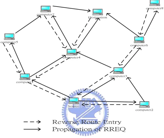
To process the RREQ, the node sets up a reverse route entry for the source node
in its route table. This reverse route entry contains the source node’s IP address and
sequence number as well as the number of hops to the source nod and the IP address
of the neighbor from which the RREQ was received. In this way, the node knows how
to forward a RREP to the source if one is received later. Figure 2.5 indicates the
propagation of RREQs across the network as well as the formation of the reverse
route entries at each of the network nodes. Associated with the reverse route entry is a
lifetime. If this route entry is not used within the specified lifetime, the route
information is deleted to prevent stale routing information from lingering in the route
table.
To respond to the RREQ, the node must have an unexpired entry for the
destination in its route table. Furthermore, the sequence number associated with that
destination must be at least as great as that indicated in the RREQ. This prevents the
formation of routing loops by ensuring that the route returned is never old enough to
point to a previous intermediate node. Otherwise, the previous node would have
responded to the RREQ. If the node is able to satisfy these two requirements, it
responds by unicasting a RREP back to the source. If it is unable to satisfy the RREQ,
it increments the RREQ’s hop count and then broadcasts the packet to its neighbors.
Chapter 2 Some routing protocols for ad hoc networks
If the RREQ is lost, the source node is allowed to retry the broadcast route
discovery mechanism. After rreq_retries additional attempts, it is required to notify
the application that the destination is unreachable.
Figure 2.5 Propagation of RREQ throughout the network
2.2.2.2 Forward Path Setup
When a node determines that it has a route current enough to respond to the
RREQ, it creates a RREP. For the purposes of replying to a RREQ, any route with a
sequence number not smaller than that indicated in the RREQ is deemed current
enough. The RREP sent in response to the RREQ contains the IP address of both the
source and destination. If the destination node is responding, it places its current
sequence number in the packet, initializes the hop count to zero, and places the length
node is responding, it places its record of the destination’s sequence number in the
packet, sets the hop count equal to its distance from the destination, and calculates the
amount of time for which its route table entry for the destination will still be valid. It
then unicasts the RREP toward the source node, using the node from which it received
the RREQ as the next hop.
When an intermediate node receives the RREP, it sets up a forward path entry to
the destination in its route table. This forward path entry contains the IP address of the
destination, the IP address of the neighbor from which the RREP arrived, and the hop
count, or distance, to the destination. To obtain its distance to thedestination, the node
increments the value in the hop count field by 1. Also associated with this entry is a
lifetime, which is set to the lifetime contained in the RREP. Each time the route is
used, its associated lifetime is updated. If the route is not used within the specified
lifetime, it is deleted. After processing the RREP, the node forwards it toward the
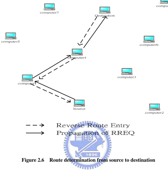
source. Figure 2.6 indicates the path of a RREP from the destination to the source
node.
It is likely that a node will receive a RREP for a given destination from more
than one neighbor. In this case, it forwards the first RREP it receives and forwards a
later RREP only if that RREP contains a greater destination sequence number or a
smaller hop count. Otherwise, the node discards the packet. This decreases the
number of RREPs propagating toward the source while ensuring the most up-to-date
and quickest routing information. The source node can begin data transmission as
soon as the first RREP is received and can later update its routing information if it
discovers a better route.
Chapter 2 Some routing protocols for ad hoc networks
Figure 2.6 Route determination from source to destination
2.2.2.3 Route Maintenance
Once a route has been discovered for a given source/destination pair, it is
maintained as long as needed by the source node. Movement of nodes within the ad
hoc networks affects only the routes containing those nodes; such a path is called an
active path. If the source node moves during an active session, it can reinitiate route
discovery to establish a new route to the destination. When either the destination or
some intermediate node moves, however, a RERR message is sent to the affected
source node. This RERR is initiated by the node upstream (i.e., closer to the source
nodes) of the break. It lists each of the destinations that are now unreachable because
as a precursor node for the destination, it broadcasts the RERR to these neighbors.
When the neighbors receive the RERR, they mark their route to the destination as
invalid by setting the distance to the destination equal to infinity and in turn propagate
the RERR to their precursor nodes, if any such nodes are listed for the destinations in
their rout tables. When a source node receives the RERR, it can reinitiate route
discovery if the route is still needed.
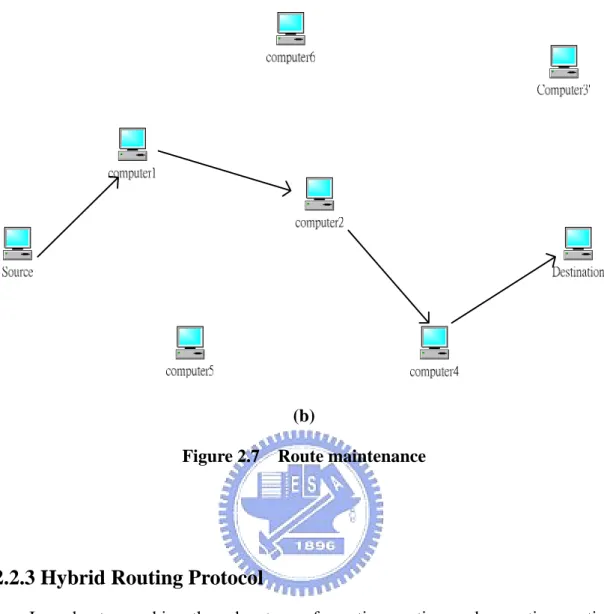
Figure 2.7 illustrates the route maintenance procedure. In Figure 2.7(a), the
original path from the source to the destination is through nodes 1, 2, and 3. Node 3
then moves to location 3’, causing a break in connectivity with node 2. Node 2 notices
this break and sends a RERR to node 1. Node 1 marks this route as invalid and then
forwards the RERR to the source. On receiving the RERR, the source node
determines that it still needs the route, and so it reinitiates route discovery. Figure
2.7(b) shows the new route found through node 4.
Chapter 2 Some routing protocols for ad hoc networks
(b)
Figure 2.7 Route maintenance
2.2.3 Hybrid Routing Protocol
In order to combine the advantage of reactive routing and proactive routing
respectively, hybrid routing protocols such as ZRP maintains local proactive routing
and global reactive routing. Interzone route discovery is based on a reactive route
request/route reply scheme. By contrast, intrazone routing uses a proactive protocol to
maintain up-to-date routing information to all nodes within its routing zone. However,
Chapter 3
Some security mechanisms
3.1 Key management
Several techniques have been proposed for the distribution of public keys.
Virtually all these proposals can be grouped into the following general schemes:
public announcement, public-key authority, and public-key certificates.
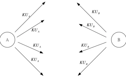
3.1.1 Public announcement of public keys
The point of public-key encryption is that the public key is public. Thus, if there
is some broadly accepted public-key algorithm, such as RSA, any participant can send
his public key to any other participant or broadcast the key to the community at large
(Figure 3.1).
Although this approach is convenient, it has a major weakness. Anyone can forge
such a public announcement. That is, some user could pretend to be user A and send a
Chapter 3 Some security mechanisms A A KU A KU A KU A KU B B KU B KU B KU B KU
Figure 3.1 Uncontrolled public-key distribution
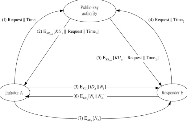
3.1.2 Public-key authority
Stronger security for public-key distribution can be achieved by providing tighter
control over the distribution of public keys from the directory. A typical scenario is
illustrated in Figure 3.2. The scenario assumes that a central authority maintains a
dynamic directory of public keys of all participants. In addition, each participant
reliably knows a public key for the authority, with only the authority knowing the
corresponding private key. The following steps (matched by number to Figure 3.2)
occur:
1. A sends a timestamped message to the public-key authority containing a request for
the current public key of B.
2. The authority responds with a message that is encrypted using the authority’s private key, KRauth. Thus, A is able to decrypt the message using the authority’s public key. Therefore, A is assured that the message originated with the authority.
The message includes the following:
z B’s public key, KU , which A can use to encrypt messages destined for B b
corresponding earlier request and to verify that the original request was not
altered before reception by the authority
z The original timestamp, so A can determine that this is not an old message
from the authority containing a key other than B’s current public key
3. A stores B’s public key and also uses it to encrypt a message to B containing an
identifier of A (IDA) and a nonce (N1), which is used to identify this transaction
uniquely.
4,5. B retrieves A’s public key from the authority in the same manner as A retrieved
B’s public key.
At this point, public keys have been securely delivered to A and B, and they may
begin their protected exchange. However, two additional steps are desirable:
6. B sends a message to A encrypted with KU and containing A’s nonce (a N1) as well as a new nonce generated by B (N2). Because only B could have decrypted
message (3), the presence of N1 in message (6) assures A that the correspondent is
B.
7. A returns N2, encrypted using B’s public key, to assure B that its correspondent is
A.
3.1.3 Public-key certificates
The scenario of Figure 3.2 has some drawbacks. The public-key authority could
be somewhat of a bottleneck in the system, for a user must appeal to the authority for
a public key for every other user that it wishes to contact. As before, the directory of
names and public keys maintain by the authority is vulnerable to tampering.
An alternative approach is to use certificates that can be used by participants to
Chapter 3 Some security mechanisms
if the keys were obtained directly from a public-key authority. Each certificate
contains a public key and other information, is created by a certificate authority, and is
given to the participant with the matching private key. A participant conveys its key
information to another by transmitting its certificate. Other participants can verify that
the certificate was created by the authority. We can place the following requirements
on this scheme:
1. Any participant can read a certificate to determine the name and public key of the
certificate’s owner.
2. Any participant can verify that the certificate originated from the certificate
authority and is not counterfeit.
3. Only the certificate authority can create and update certificates.
4. Any participant can verify the currency of the certificate.
A certificate scheme is illustrated in Figure 3.3. Each participant applies to the
certificate authority, supplying a public key and requesting a certificate. Application
must be in person or by some form of secure authenticated communication. For
participant A, the authority provides a certificate of the form
[ , , ]
auth
A KR A a
C =E T ID KU , where KRauth is the private key used by the authority. A may then pass this certificate on to any other participant, who reads and verifies the
certificate as follows: [ ] [ [ , , ]] ( , , )
auth auth auth
KU A KU KR A a A a
D C =D E T ID KU = T ID KU . The recipient uses the authority’s public key to decrypt the certificate. Because
the certificate is readable only using the authority’s public key, this verifies that the certificate came from the certificate authority. The elements IDA and KUA provide
the recipient with the name and public key of the certificate’s holder. The timestamp T
1 (1) Request || Time 1 (2) E [ || Request || Time ] auth KR KUb 1 (3) E [ || ] b KU IDA N 1 2 (6) E [ || ] a KU N N 2 (7) E [ ] b KU N 2 (5) E [ || Request || Time ] auth KR KUa 2 (4) Request || Time
Figure 3.2 Public-key distribution scenario
Initiator A Responder B Certificate authority 1 [ , , ] auth A KR A a C =E Time ID KU (1)CA (2)CB 2 [ , , ] auth B KR B b C =E Time ID KU a KU KUb
Chapter 3 Some security mechanisms
3.2 Diffie-Hellman key exchange
The purpose of the algorithm is to enable two users to exchange a key securely
that can then be used for subsequent encryption of message. First, we define a primitive root of a prime number p as one whose powers generate all the integers
from 1 top− . That is, if a is a primitive root of the prime number p , then the 1 numbers amodp,a2modp ,L,ap−1modp are distinct and consist of the integers from 1 through p− in some permutation. For any integer 1 b and a primitive root
a of prime number p , we can find a unique exponent i such that b≡ai mod p, where 0≤ ≤i (p− . The exponent i is referred to as the discrete logarithm, or index, 1) of b for the base a, mod p . This value is denoted as inda p, ( )b . With this
background we can define the Diffie-Hellman key exchange, which is summarized in
Figure 3.4.
For this scheme, there are two publicly known numbers: a prime number q
and an integer α that is a primitive root of q . Suppose the user A and B wish to exchange a key. User A selects a random integer XA <q and computes XA mod
A
Y =α q . Similarly, user B independently selects a random integerXB <qand computes XB mod
B
Y =α q. Each side keeps the X value private and makes the Y value available publicly to the other side. User A computes the key
as ( )XA mod
B
K = Y q and user B computes the key as ( )XB mod
A
K = Y q. These two calculations produce identical results:
( ) mod
( mod ) mod
( ) mod by the rules of modular arithmetic mod ( ) mod ( mod ) mod ( ) mod A B A B A B A A B A B B X B X X X X X X X X X X X A K Y q q q q q q q q Y q α α α α α = = = = = = =
The result is that the two sides have exchanged a secret key. Furthermore,
because XA and XB are private, an opponent only has the following ingredients to
work with: q ,α ,YA,YB. Thus, the opponent is forced to take a discrete logarithm to determine the key. For example, attacking the secret key of user B, the opponent must
compute XB =indα,q(YB). The opponent can then calculate the key K in the same manner as user B calculate it.
Prime number
and a primitive root of
q
q q
α α < α
Select private
Calculate public A mod
A A X A A X X q Y Y α q < = Select private
Calculate public B mod
B B X B B X X q Y Y α q < = ( )XA mod B K= Y q ( )XB mod A K= Y q
Chapter 3 Some security mechanisms
The security of the Diffie-Hellman key exchange lies in the fact that, while it is
relatively easy to calculate exponentials modulo a prime, it is very difficult to
calculate discrete logarithms. For large primes, the latter task is considered infeasible.
Here is an example. Key exchange is based on the use of the prime number 353
q= and a primitive root of 353, in this case α =3. A and B select keys 97
A
X = and XB =233, respectively. Each computes its public key: A computes
97
3 mod 353 40
A
Y = = , B computes YB =3233mod 353=248 After they exchange public keys, each can compute the common secret key: A computes
97 ( )XAmod 353 248 mod 353 160 B K = Y = = . B computes 233 ( )XBmod 353 40 mod 353 160 A K = Y = = .
We assume an attacker would have available the following information:
353; 3; A 40; B 248
q= α = Y = Y = . In this simple example, it would be possibly by brute force to determine the secret key 160. In particular, an attacker E can determine the
common key by discovering a solution to the equation 3 mod 353a =40or the equation 3 mod 353b =248
. The brute force approach is to calculate powers of 3 modulo 353, stopping when the result equals either 40 or 248. The desired answer is
reached with the exponent value of 97, which provides 3 mod 35397 =40. It is important that with larger numbers, the problem becomes impractical.
Figure 3.5 shows a simple protocol that makes use of the Diffe-Hellman
Generate
random
;
Calculate
mod
Calculate
( )
mod
A A A X A X BX
q
Y
q
K
Y
q
α
<
=
=
Generate
random
;
Calculate
mod
Calculate
( )
mod
B B B X B X AX
q
Y
q
K
Y
q
α
<
=
=
Figure 3.5 Diffie-Hellman Key Exchange
3.3 Summary
The certificate authority mechanism is hard to apply to the mobile ad hoc
networks. Each node always moves and will leave the network at any time. If we
choose one node to be the certificate authority, it may leave at next second. Then, we
have to choose another node to be the certificate authority. This will make the control
overhead too heavy. So we use the Diffie-Hellman key exchange algorithm in our
Chapter 4 Proposed secure routing protocol
Chapter 4
Proposed secure routing protocol for mobile ad
hoc networks (MANETs)
The main idea proposed in this thesis is the exchange of a secret key securely,
without a centralized key distribution mechanism and the idea that can accomplish
dynamic and fast route reconfiguration using information about redundant paths
maintained at a source node and intermediate nodes on the main route.
4.1 Redundancy Based Multi-path Routing protocol
In dynamic ad hoc networks, route re-discoveries due to route failures may incur
heavy control traffic through the network and cause the increase of packet
transmission delay. Hence it is quite required to reduce the number of route
re-discoveries by maintaining multiple redundant paths, establishing alternate route
promptly and localizing the effect of the failures. Redundancy based multi-path
routing (RBMR) [16] protocol that provides dynamic and fast route reconfiguration
using information about redundant paths maintained at a source and intermediate
nodes on initial route.
4.1.1 Path redundancy
redundancy is expressed by the sum of ‘redundancy degrees’ of intermediate nodes
involved in the route. Each node’s redundancy degree signifies the number of
redundant links that a node has except one incoming link and outgoing link involved
in routing. RBMR is based on the idea that a route with large path redundancy will
have more possible redundant paths toward the destination even though there can not
exist as many redundant paths as the number of neighbor nodes at each intermediate
node. A route with more redundant paths will have the improved reach-ability to the
destination in case of route failures. If several possible routes are found during a route
discovery process, the path redundancy is considered as an important factor in
selecting the desired route. However, the hop distance of the route selected may be
longer than in routing algorithms, such as DSR, which selects the shortest path from
source to destination. To prevent a route with a relatively excessive hop distance
being selected, RBMR will choose the route that has the largest path redundancy per
hop, but is not a certain size longer than the hop distance of the shortest candidate
route.
4.1.2 Route establishment
Route establishment with RBMR follows a route setup/route reply cycle like
typical on-demand ad hoc routing protocols. In this procedure, main route and
redundant routes are established. RBMR’s operations are based on the assumptions
that wireless links between neighboring nodes are symmetric and that each node is
aware of the number of nodes in its neighborhood with the help of a data link layer
protocol.
4.1.3 Route setup process
Chapter 4 Proposed secure routing protocol
message, Route Setup (RS) packet. An RS packet is flooded throughout the network
as shown in Figure 4.1 and carries the information about hop distance and redundancy
degree of nodes that it goes through. Any node that receives an RS packet does the
following: If the node has already received the RS packet with the same identification,
it records the address of the node from which it received the packet as a redundant
upstream node and then drops that packet. The recorded node address will be used to
build a redundant path if this node is involved in the selected route. If the node
recognizes its own address as the destination, it records the forwarding node address,
hop count and path redundancy of the packet. To secure the route with more
redundancy, the destination will wait for a certain number of RS packets to reach it
after receiving the first RS packet. The destination node can receive several RS
packets transmitted along different paths from the source node. An RS packet
delivered along the shortest route will early reach the destination node and RS packets
representing routes with more redundant links may come to later. The destination
node adopts the RS packet that reached it later, but contained larger path redundancy
per hop, and sends a Route Reply (RR) packet back to the source node via the node
from which it received the RS packet. Otherwise, the node records the address of the
neighbor node from which it received the RS packet as the upstream node. The
recorded node address will be used to build a route during the route reply process.
Then, it adds its own redundancy degree to that of the RS packet and broadcasts the
updated packet to its neighbor nodes.
Figure 4.1 illustrates how an RS packet is flooded in the entire network. The
number under indicates each node’s redundancy degree. The node that has the largest
redundancy degree is N6. Its redundancy degree is four. Namely, N6 has four
redundant nodes. Each intermediate node does not propagate duplicate RS packets.
shortest one in the example network. Its hop distance id four and its redundancy
degree is one. The other RS packet is delivered along the path,
N1-N3-N6-N12-N13-N11. This path has one more hop distance and five larger route
redundancy degree than the previous one. RMBR chooses the second path as a route.
Figure 4.1 The route setup packet flooding
4.1.4 Route reply process
A route containing redundant paths toward the destination is established during
the route reply process. The destination node initiates the route reply process by
sending an RR packet back to the source node via the node from which it received the
corresponding RS packet. An RR packet is forwarded back along the transit nodes the
TS packet was traversed. An RR packet carries the hop distance from the destination
Chapter 4 Proposed secure routing protocol
whenever the RR packet is forwarded at each intermediate node. Any node that
receives an RR packet does the following. If the node recognizes itself as the target
node of the received RR packet, it records the forwarding node address of the packet
as the next hop for the destination. Then, the node increments the hop distance of the
received packet and sends the updated packet to its upstream node, which was
recorded during the route setup process. Moreover, if the node has any redundant
upstream node recorded, it generates and sends the Redundant Route Reply (RRR)
packet to the redundant neighbor nodes. The hop distance of the RR packet is copied
into the hop distance field of the RRR packet. If the node recognized its own address
as the source, it records the forwarding node address of the RR packet as the next hop
for the destination in the route table. Otherwise, the node discards the RR packet.
The RRR packet is used to setup a redundant path of a route. An RRR packet is
originated from only nodes along a main route if they have redundant nodes in the
upstream direction. RRR packets are forwarded at redundant nodes toward the source
node. Any node that receives an RRR packet does the following: If the node exists
along the main route, it creates the redundant route table (RRT) entry, which is a set of
redundant neighbor nodes for the destination. A redundant next hop field of the RRT
entry is filled with the forwarding node address of the RRR packet. If the node is
along a redundant path and has already received the RRR packet with the same
identification, it discards the packet. This means that a redundant path cannot have
any redundant path for itself. Otherwise, it records the forwarding node address of the
RRR packet as a redundant next hop for the destination in the RRT entry. Then, it
forwards the packet to the upstream nodes.
Figure 4.2 illustrates the route reply process including redundant path setup.
When the destination node N11 receives two RS packets from possible routes and as
redundant paths toward N11 at N6 and N12. N6 has two redundant links N6-N9 and
N6-N10. To establish a route, N11 sends an RR packet back to the forwarding node
N13 of the chosen RS packet. The RR packet is unicast to the source. Nodes receiving
the RR packet increment the hop distance by one and then create or update route
information for the destination. Once the RR packet reaches the source, the source
begins the transmission of data packets. In this example, the data packets are
transmitted along the established route N1-N3-N6-N12-N13. As for the redundant
route setup, a node receiving an RR packet generates an RRR packet if it has any
redundant upstream node. In Figure 4.2 (a), since N13 is along a main route and has a
redundant upstream node N14, it generates and sends an RRR packet to N14. If N14
receives the RRR packet, it records redundant path information. The RRR packet is
disseminated to other upstream nodes along a main route. In this example network,
the RRR packet originating from N13 is delivered to N12 and N6. The two main
nodes create the redundant route entry and maintain the redundant path information
for N11. N12 has one redundant path N12-N14-N13, and N6 three redundant paths
N6-N9-N12 (four hops), N6-N10-N14-N12 (five hops), N6-N10-N14-N13 (four
hops). Figure 4.2 (b) shows the route established. In the event of a link failure
between N6 and N12, N6 can forward in-transit data packets via one of three
Chapter 4 Proposed secure routing protocol
(a) The route reply process
(b) Example of an established route Figure 4.2 Example of route establishment
4.1.5 Route reconfiguration
4.1.5.1 Failure notification
When a node detected a link failure, but did not have any redundant path for the
destination. Route failure information is carried using a Failure Notification (FN)
packet and stored in the failure record. Route failure information includes the
information about a failure-detecting node, whether the failure-detecting node is along
a main route or not, and intermediate transit nodes that an FN packet is propagated
through. Any node that receives an FN packet does the following: If the node is along
a main route (shortly, main node) and the FN packet is originating from a main node,
it records the failure information and finds an alternate redundant path. If the node is a
main node and the FN packet is originating from a node along a redundant path
(shortly, redundant node), it removes the corresponding redundant path information
from the RRT entry. If the node is a main node and the FN packet is originating from
a node along an active redundant path (shortly, active redundant node), it records the
failure information and finds an alternate redundant path. If the node cannot find a
redundant path, it adds its node address to the FN transit node list of the FN packet
and propagates the updated packet. Moreover, it deletes all the information about the
failure route. If the node is an active redundant node, it deletes the corresponding
Routing Table (RT) entry and RRT entry and adds its node address to the FN transit
node list of the FN packet and propagates the updated packet. If the node is an
inactive redundant node, it deletes the corresponding RRT entry and broadcasts the
packet.
4.1.5.2 Finding an alternate path
Chapter 4 Proposed secure routing protocol
any more data packets through its outgoing link in use, it begins the procedure to find
an alternate path. In the first place, the failure-recognizing node checks if it maintains
any redundant path related to the failed route. If the node does not have any redundant
path, it tries to finds an alternative redundant path. If a node fails to find a redundant
path and is the source node, it initiates a route discovery procedure.
4.1.6 RBMR compare with DSDV and AODV
Figure 4.4 Packet delivery ratio
Figure 4.5 Control traffic overhead
4.2 RBMR with Diffie-Hellman key exchange algorithm
Chapter 4 Proposed secure routing protocol
for RBMR with Diffie-Hellman key exchange algorithm is presented. Before
transmitting the data, the node should perform a route discovery process, to determine
whether the node is directly reachable within the wireless transmission range or
reachable through one or more intermediate network hops through other hosts. When
one host sends a packet to another host, the sender may attempt to discover one route
using the route setup process. As part of route setup process a route request is
broadcast, all the neighbor nodes retransmit this. When it reaches the destination, the
destination responds with a route reply message containing the information, to the
source. The source sends the data packets using the route.
Our proposed protocol involves the incorporation of the proposed security
mechanism in the basic RBMR protocol. The main addition is the handling of the
token exchange process prior to key determination. This is incorporated as a part of
the route setup process. The source token is generated using the Diffie-Hellman
method. It is added to the route request packet to be sent to the destination. The
format of the route request packet with the source token is given in table 4.3.
Packet type (RS) Source address Destination address Hop count Redundancy degree Source token Route record Packet ID
As in RBMR, the destination receives a number of route request packets which
have traveled through different paths. However, the destination does not send the
reply packets as soon as it receives the first request. The destination extracts the
source token from all the request packets it receives, and compares them. The value
that has been received maximum number of times is taken to be the correct source
token. Destination now sends reply packets on the routes having the correct token and
an error message is broadcast so that other nodes may get the indication of the
particular route that is likely to have a malicious node. The reply packets contain the
destination token to be sent to the source. The destination token is derived using the
Diffie-Hellman process. The format of the reply packet and error message packet are
given in table 4.2 and 4.3.
After retrieving the destination token, the source generates the secret key using
the Diffie-Hellman algorithm. The destination also generates the secret key in the
same manner. The secret key generated by both the source and the destination will be
the same according to Diffie-Hellman method. Using this secret key, data is encrypted
using any conventional encryption algorithm. The same secret key can be used for
further communication between the two nodes.
Packet type (RR) Source address Destination address Destination token Route record Hop count
Chapter 4 Proposed secure routing protocol
Packet type (FN)
Detecting node address
Route record
Table 4.3 Error message packet format
In our proposed algorithm, the destination node cannot send the reply packet as
soon as it receives the route request. It has to wait until it receives all the route request
packets, so that it can compare them and extract the token information. The problem
here is that the destination node has no way of determining when all the packets have
been received. Hence, practically, it has to wait for a certain threshold number of
packets to be received, before it starts the route reply process. Determining the
threshold is hard. The threshold value has to be large enough for the success of this
algorithm, since a good number of correct tokens have to be received. (Malicious
nodes send wrong tokens, and the number of correct tokens should be greater than the
number of wrong tokens for the success of our proposed algorithm.). However a large
value for the threshold could increase the waiting time before the token-extraction
processing at the destination can be done. This could cause a delay in the route
discovery process. So, this is a trade-off problem. How many requests should be
received is also depend on the density of the network. Thus choosing the threshold
Chapter 5
Conclusions
In mobile ad hoc networks, each mobile host will always move and the topology
will change all the time. The links between hosts will be broken easily, so it is
important to use a routing protocol which can find another route fast when link is
broken. Under wireless transmission, To keep the data transmission secure is very
important. Our proposed algorithm can achieve both routing reconfiguration fast and
data encryption easily. It has less control overhead. This algorithm provide an easy
Bibliography
Bibliography
[1] Lidong Zhou and Zygmunt J. Haas, “Securing Ad Hoc Networks,” IEE Network Magazine, Volume 13, Issue 6, Nov.-Dec. 1999, page(s):24 - 30.
[2] S. Marti, T.J. Giuli, K. Lai and M. Baker, “Mitigating Routing Misbehavior in Mobile Ad Hoc Networks,” Proceedings of the 6th annual international conference on Mobile computing and networking, 2000, page(s):255 – 265.
[3] B. Dahill, B. Levine, E. Royer and C. Shields, “A Secure Routing Protocol for Ad Hoc Networks.”
[4] P. Papadimitrators and Z. J. Hass, “Secure routing for Mobile Ad Hoc Networks,” SCS Communication Networks and Distributed Systems Modeling and Simulation Conference (CNDS 2002), San Antonio, TX, January 27-31,2002.
[5] R. Perlman, “Network Layer Protocols with Byzantine Robustness,” Ph.D. thesis, Department of Electrical Engineering and Computer Science, Massachusetts Institute of Technology, 1988.
[6] B. Kumar, “Integration of security in network routing protocols,” SIGSAC Reviews, vol. 11, no. 2, 1993, pp. 18-28.
[7] S. Murphy and J. J. Garcia-Luna-Aceves, “An Efficient Routing Algorithm for Mobile Wireless Networks,” MONET, Oct. 1996, vol. 1, no. 2, pp. 183-197.
[8] K. E. Sirois and S. T. Kent, “Securing the Nimrod Routing Architecture,” Proc. Symposium on Network and Distributed System Security, Los Alamitos, CA, Feb. 1997, The Internet Society, IEEE Computer Society Press, pp. 74-84.
[9] B. R. Smith, S. Murphy and J. J. Garcia-Luna-Aceves, “Securing Distance-Vector Routing Protocols,” Proc. Symp. Network and dist. Sys. Security, Los Alamitos, CA, Feb. 1997, pp. 85-92.
[10] V. D Park and M. S. Corson, “A Highly Adaptive Distributed Routing Algorithm for Mobile Wireless Network,” Proceedings of the IEEE International Conference on Computer Communications (INFOCOM), Kobe, Japan, April, 1997, pp. 1405-1413.
[11] Castaneda R, Das SR. Query localization techniques for on-demand routing protocols in ad hoc networks. Proceedings of the ACM/IEEE International Conference on Mobile Computing and Networking (MobiCom); Seattle, WA, August 1999, pp. 186-194.
[12] David B. Johnson, David A. Maltz, Yih-Chun Hu, “The Dynamic Source Routing Protocol for Mobile Ad hoc Networks (DSR),” draft-ietf-manet-dsr-09.txt, 15 April, 2003.
[13] S.J Lee, M. Gerla, and C. C. Chiang, “On-Demand Multicast Routing Protocol,” Proceedings of the IEEE Wireless communications and Networking Conference (WCNC), New Orleans. LA, September 1999, pp. 1298-1302.
[14] Charles E. Perkins, Elizabeth M. Belding-Royer, Samir R. Das, “Ad hoc On-Demand Distance Vector (AODV) Routing,” Internet-Draft, draft-ietf-manet-aodv-13.txt, 17 February, 2003.
[15] Charles E. Perkins, “Ad Hoc Networking.” pp. 139-168.
[16] Sangyung Kim, Wonjong Noh, and Sunshin An, “Multi-path Ad Hoc Routing Considering Path Redundancy,” Proceedings of the IEEE International Symposirm on Computers and Communication, 2003.
[17] William Stallings, “Cryptography and Network Security.”