國
立
交
通
大
學
多媒體工程研究所
碩
士
論
文
利 用 以 消 失 點 為 基 礎 之 新 模 型
從 單 一 視 角 進 行 立 體 視 訊 合 成
Stereoscopic View Synthesis from Monocular Video
using the Novel Vanishing Point-Based Model
研 究 生:韓建智
指導教授:蕭旭峯 教授
利用以消失點為基礎之新模型從單一視角進行立體視訊合成
Stereoscopic View Synthesis from Monocular Video
using the Novel Vanishing Point-Based Model
研 究 生:韓建智 Student: Chien-Chih Han
指導教授:蕭旭峯 Advisor:Hsu-Feng Hsiao
國 立 交 通 大 學
多 媒 體 工 程 研 究 所
碩 士 論 文
A Thesis
Submitted to Institute of MultimediaEngineering College of Computer Science
National Chiao Tung University in partial Fulfillment of the Requirements
for the Degree of Master
in
Computer Science
August 2008
Hsinchu, Taiwan, Republic of China
- i -
利用以消失點為基礎之新模型從單一視角進行立體視訊合成
研究生: 韓建智 指導教授: 蕭旭峯
國立交通大學多媒體工程研究所
摘要
隨著現今立體顯示技術(多視角影像擷取器材以及相關的壓縮編碼演算法)的發 展,它所帶來的立體視覺體驗,已經令使大家逐漸地產生興趣。然而為了產生具有深度 的感受,無論是拍攝或者以單一視角/多視角合成的方法,產生雙眼視角的兩隻不同影片 是必要的。在這篇論文中,我們提出一個從單一視角產生立體影片的方法。這個方法先 將背景和物體分割後,然後再進行座標軸轉換來合成立體影片。我們提出的演算法是利 用單一視角影片中的消失點和消失線所產生的立體空間模型,進行影像座標和世界座標 之間的轉換,經由這個轉換後,再模擬出另一視角攝影機的位置,進行反轉換產生立體 影片。最後,我們除了會放上產生的立體影像來展示立體效果外,還會將合成的影像和 真實影像以 PSNR 進行比較,以此來客觀地表示以此方法產生影片的相似程度。- ii -
Stereoscopic View Synthesis from Monocular Video using the
Novel Vanishing Point-Based Model
Student: Chien-Chih Han Advisor: Hsu-Feng Hsiao
Institute of Multimedia Engineering
National Chiao Tung University
ABSTRACT
With the recent progress of stereoscopic display technology, multiview capture devices, and the corresponding coding algorithms, stereoscopic viewing experience has been introduced to the public with growing interest. To create the depth perception, two different video sequences in binocular vision are captured or synthesized from the monocular/multiview video sequences. In this paper, we produce the stereoscopic videos out of the monocular sequences by means of the background/object separation and the coordinates transformation. The proposed algorithms transform the image coordinate into the world coordinate based on the vanishing model constructed from vanishing point and vanishing lines of the monocular video. At last, we would exhibit the experimental results to show the stereoscopic effect and compare the synthesized views with raw data in PSNR to represent the similarity from the proposed algorithm.
- iii -
---
Acknowledgement
---
本篇論文能夠完成,首先要感謝我的指導教授蕭旭峯博士,在我遇到無數次的瓶 頸時,他的建議及意見往往讓我茅塞頓開,從問題的發現到解決的過程更是學習的重 點,相信他對研究的熱忱與認真的態度,已經深深地影響著我;也感謝我的口試委員賴 文能教授及蔡文錦教授,他們在口試時給予的寶貴意見,使得本篇論文更加完善。 我也要感謝我的學長們:范姜智為、石新嘉及張玉書,在與他們的討論和研究下, 使我解決不少難題;另外我也要感謝實驗室的夥伴們:怡禎、群志、家銘、忠穎、彥暉、 詠霆、伯恆、峻豪、旻璟、晨洲、德沛以及昀修,他們讓我的研究所生涯充滿了歡笑, 也在他們的鼓勵及幫助下,讓我能夠順利地完成的這篇論文。此外,我也要感謝羽球隊 教練兼體育室主任廖威彰,他在我全力充刺學業,對球隊的貢獻微乎其微時,仍然給予 我不少練習的資源,並且也給予我不少待人處事以及人生規劃的經驗分享。最後,我要 感謝我的家人,他們給予我全力的支援,讓我能夠在無後顧之憂的情況下,完成我的碩 士學位,感謝所有的朋友。- iv -
---
Contents
---
摘要 ... i ABSTRACT ... ii Acknowledgement ... iii Contents ... iv List of Figures ... viChapter 1. INTRODUCTION AND RELATED WORK ... 1
1.1 Introduction ... 1
1.2 Multiview View Synthesis ... 1
1.3 Monocular view synthesis with mobile camera ... 3
1.4 Monocular view synthesis with immobile camera ... 5
Chapter 2. PREPROCESSING ALGORITHMS FOR VIEW SYNTHESIS ... 6
2.1 Moving Object Detection ... 7
2.2 Vanishing Point Extraction ... 11
Chapter 3. VIEW SYNTHESIS ... 15
3.1 Stereoscopic Model ... 15
3.2 Background Projection ... 16
3.3 Moving Object Projection ... 25
3.4 View Synthesis ... 27
Chapter 4. EXPERIMENT RESULT ... 29
4.1 Related Results ... 29
4.1.1 Stereoscopic Video Synthesis from a Monocular Video [4] ... 29
4.1.2 Depth Map Generation for 2D-to-3D Conversion by Short-Term Motion Assisted Color Segmentation [5] ... 30
4.1.3 3D Stereoscopic Image Pairs by Depth-Map Generation [6] ... 32
4.2 Results of Proposed Method ... 33
4.2.1 Subjective Results ... 33
4.2.2 Subjective Result of Predefined Initial Depth Value ... 38
4.2.3 Objective Results ... 39
- v -
5.1 Conclusion ... 42 REFERENCES ... 43
- vi -
---
List of Figures
---
Figure 1- Relation between depth and disparity. ... 2
Figure 2- Configuration of depth map generation and view synthesis. ... 3
Figure 3- Absolute parallax and relative parallax [4]. ... 5
Figure 4- Block diagram of the proposed method. ... 6
Figure 5- Block diagram of the moving object detection. ... 8
Figure 6- Frame difference of video lovebird1 (camera 1) with different operations: ... 9
Figure 7- The results of moving object detection. ... 11
Figure 8- The vanishing lines of (A) is the camera 1 of lovebird1, (C) is the homemade video. ... 13
Figure 9- Five examples of vanishing situations: the green circle represents the vanishing point [6]. ... 13
Figure 10- Region of vanishing point and main vanishing lines. ... 14
Figure 11- image coordinate and world coordinate. ... 16
Figure 12- The related position between vanishing point and the middle of screen when (A) camera aims at the farthest, (B) camera aims at the upper horizontal plane, (C) camera aims at the lower horizontal plane. ... 18
Figure 13- Illustrate the derivation to d and h with the point P located between (A) V and M, (B) M and B, at the case with camera aimed at the lower horizontal plane, (C) at the case with camera aimed at the upper horizontal plane. ... 20
Figure 14- Another viewpoint from Fig. 13-A for illustration. ... 21
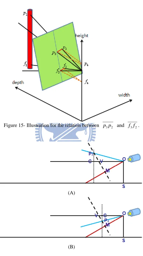
Figure 15- Illustration for the relation between p3p2 and f3f2. ... 24
Figure 16- The cross-sectional view on plane w=0 from Fig. 15. ... 25
Figure 17- An example of stereoscopic video generation. ... 30
Figure 18- Subjective view results ... 31
Figure 19- (A) Original outdoor with geometric appearances image (B) Geometric depth map (C) Qualitative depth map through [12] (D) Final depth map (E) Anaglyph image [6]. ... 33
Figure 20- the camera 5 of lovebird1 (A) The original view, (B) The synthesized view, (C) The depth map of (A), (D) Red-cyan anaglyph. ... 34
- vii -
Figure 21- another view of the camera 5 of lovebird1 (A) The original view, (B) The
synthesized view, (C) The depth map of (A), (D) Red-cyan anaglyph. ... 35 Figure 22- Camera 7 of Alt Moabit (A) The original view, (B) The synthesized view, (C) The depth map of (A), (D) Red-cyan anaglyph. ... 36 Figure 23- homemade video (A) The original view, (B) The synthesized view, (C) The depth map of (A), (D) Red-cyan anaglyph. ... 37 Figure 24- the depth map of manual initial depth value. (A) The frame #1 of Alt Moabit, (B) The frame #40 of Alt Moabit, (C) The frame #60 of Alt Moabit. ... 39 Figure 25- Synthesize the camera 6 of lovebird1 from single view and multiview synthesis. . 40 Figure 26- Synthesize camera 8 of Alt Moabit from single view and mutiview synthesis. ... 41
- 1 -
Chapter 1.
INTRODUCTION AND RELATED
WORK
1.1 Introduction
The depth perception of stereoscopic vision can be created by feeding each eye with two different video sequences or images in binocular vision with proper parallax, respectively. Unless video scenes are captured with a pair of synchronized cameras that are separated and directed to the scenes properly, view synthesis is usually performed to generate two views for stereoscopic vision. View synthesis could be roughly classified into two categories in terms of the types of the video sources, including multiview videos and traditional single-view videos.
1.2 Multiview View Synthesis
Stereoscopic view synthesis from multiview videos has attracted much attention to the standard development recently. Many of the view interpolation algorithms assume that video sequences are captured by aligned cameras. The depth map is created after the disparity vector map is estimated [1][2][3]. In [1], the disparity vectors are estimated between both the left view and the right view. It uses Sum of Absolute Differences (SAD) to calculate the least difference in search range. But there is only one disparity vector for each pixel. Therefore, it
- 2 -
is necessary to determine which one is the most suitable disparity vector. The difference value of SAD which is calculated before has been stored for the comparison between the disparity vector from left view and from right view. The disparity vector with less difference is considered as the proper one.
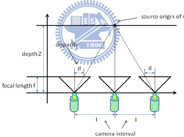
And then, the depth map is generated through the disparity vectors. Fig. 1 illustrates the relation between depth and disparity. The ratio of disparity d to focal length f equals to the ratio of camera interval I to depth Z. Camera interval and focal length could be known through the given camera parameters. So, we would get the depth value when the disparity is known. The intermediate view is then synthesized by the depth map and the occlusion regions shall be compensated.
Figure 1- Relation between depth and disparity.
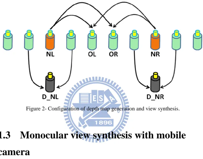
Fig. 2 shows the configuration of depth map estimation and view synthesis. NL and NR represent the original view for left and right respectively, OL and OR represent the
- 3 -
synthesized view for left and right respectively. D_NL means the depth map of NL. D_NL is generated by left and right view of NL. When there are NL, NR, D_NL, and D_NR, we could synthesize the intermediate view OL or OR.
Figure 2- Configuration of depth map generation and view synthesis.
1.3 Monocular view synthesis with mobile
camera
Besides stereoscopic video, view synthesis from multiview videos can be used in the applications of free viewpoint television as well. However, the cost of capturing synchronized multiview video sequences is expensive.
On the other hand, the monocular videos such as current DVD titles are more popular, but the information of monocular video in order to synthesize the corresponding stereoscopic video is much less in comparison with the multiview videos.
- 4 -
from monocular videos presents great challenge. In the work [4], it is assumed that the camera motion contains translational movement and the scene is stationary. With the assumption, the camera motion is tracked and the virtual view is warped by motion parallax without recovering the depth map.
Zhang et al. proposed three steps to synthesize stereoscopic video from monocular one. They tracked the camera motion by a camera-tracking algorithm at first. And then, a optimization algorithm is utilized for determining the proper base frame to warp for synthesis. To determine the optimal base frame, they proposed an optimization algorithm for three purposes: the realistic of stereoscopic effects after warping, the similarity between the warped views and original ones, and temporal smoothness.
In the realistic part, they adopt relative parallax instead of absolute parallax and decrease the warping error by minimizing the displacement of viewpoints. Fig. 3 explains why the relative parallax is more sensitive than the absolute parallax. The object in Fig. 3-B and Fig. 3-C are both moved closer, but the object in Fig. 3-C is also flattened. Therefore, the absolute parallax is increased, but its relative parallax decreases. In similarity, they get the orientation of the two chosen base frames as closer as possible. The discontinuity is mainly caused by unsteady rotation and translation speed. To smooth the synthesize view, it takes the orientation and displacement into account with different weights respectively. It is similar to decrease warping error and increase similarity.
- 5 -
(A) (B) (C) Figure 3- Absolute parallax and relative parallax [4].
1.4 Monocular view synthesis with immobile
camera
In the case of immobile camera setting, the approach to estimate the map of disparity vectors between the given video and the synthesized one usually relies on the detection of moving objects. The moving objects are classified as the nearest to the camera through motion and color segmentation as shown in [5]. If there are stationary objects in the scene, vanishing lines and vanishing points are retrieved to generate the depth map [6].
The disparity vector between a monocular video and synthesized video are estimated based on the similar aspect of [6]. Instead of estimating depth map with gradient of vanishing lines in [6], the proposed method synthesizes the virtual view through transforming and shifting of coordinates. However, the short of information in monocular video may result in the inaccuracy of estimated disparity. For this reason, we make some assumptions to restrict the condition of monocular video. It is assumed that the camera is fixed and there are vanishing lines in the captured scene. The remainder of this paper is organized as follows. In Chapter 2, moving object detection and vanishing line extraction in the proposed view synthesis are presented as the preprocessing for view synthesis. In Chapter 3, the view synthesis based on the results of moving object detection and vanishing line extraction for the corresponding stereoscopic view is described. The simulation results are shown in Chapter 4, followed by the conclusion remark in Chapter 5.
- 6 -
Chapter 2.
PREPROCESSING ALGORITHMS
FOR VIEW SYNTHESIS
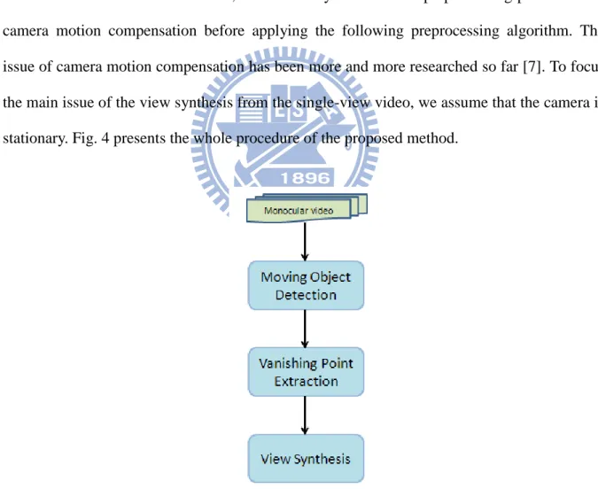
The assumption of the proposed method is immobile camera setting. If the input video which is made with camera motion, it is necessary to take more preprocessing procedure for camera motion compensation before applying the following preprocessing algorithm. The issue of camera motion compensation has been more and more researched so far [7]. To focus the main issue of the view synthesis from the single-view video, we assume that the camera is stationary. Fig. 4 presents the whole procedure of the proposed method.
Figure 4- Block diagram of the proposed method.
There are two components in the preprocessing for the view synthesis: moving objective detection and vanishing line/point extraction.
- 7 -
2.1 Moving Object Detection
The first step of preprocessing is to extract the moving objects from a given video. The disparity map of the moving objects differs from the disparity map of the background. To avoid the disparity confusion and also to make the vanishing line extraction described in the next subsection easier, moving object detection is processed first.
The moving object detection in the proposed view synthesis algorithm is based on the modification of the moving object segmentation in [8]. Instead of other object segmentation algorithms which are based on motion in [9][10], the algorithm is based on the background registration to distinguish objects in a video.
To construct the background information, Chien et al. assume that the global motion due to camera motion of the input sequence has been properly compensated and the background region can be considered stationary [8]. The flow chart of the modified moving object detection is shown in Fig. 5, including frame difference estimation, background registration, object detection, and post processing.
The objective of the frame difference estimation is to calculate the difference between the consecutive frames by a threshold. It is the fundamental operator to find the changed regions. However, the threshold method of the difference just detects the rough shape of the moving objects as shown in Fig. 6-A. Since the background is constructed only from the stationary pixels, the regions considered stationary will result in erroneous judgment as shown in Fig. 6-B.
To counter the drawback, we modify the work in [8] by spreading the rough shape of the moving objects to the neighborhood with the dilation operator when the patterns of the neighborhood are similar. However, if the dilation is over the entire region of the detected
- 8 -
pixels, more stationary pixels would be considered as moving ones. If a pixel in the current frame is similar to its neighbor but that pixel in the previous frame is not, it means that the object moves out of the video frame. If a pixel in the previous frame is similar to the neighbor but that pixel in the current frame is not, it suggests that the object moves into the video frame. Thus, the dilation operator is only performed when a pixel is similar to the neighboring pixels in the same direction over several consecutive frames as shown in Fig. 6.
In Fig. 6-C and E, it is the result which dilates the rough shape of moving objects without restriction and with restriction respectively. There are less background pixels to be classified as the moving objects with restriction than the ones without restriction. The erroneous judgment could affect the result of background registration as shown in Fig. 6-D and F respectively. In Fig. 6-D, there are some region without information because those background pixels are classified as the moving pixels.
- 9 -
(A) (B)
(C) (D)
(E) (F)
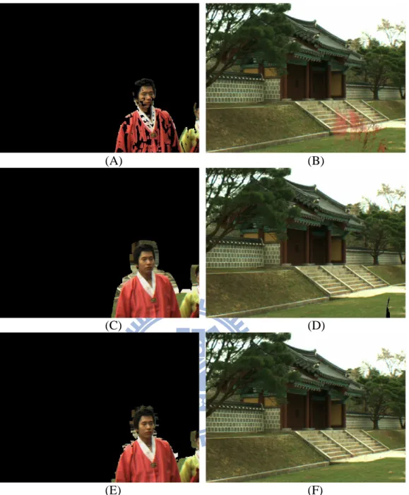
Figure 6- Frame difference of video lovebird1 (camera 1) with different operations: (A) frame difference only, (C) frame difference with dilation, (E) frame difference with
restricted dilation, and (B)(D)(F) is the result of background registration respectively.
For each video frame, the frame difference mask roughly represents whether a pixel is stationary or not. If a pixel has been stationary over several frames, it is considered as the background pixel in the background registration algorithm. To decrease the possible noise and error of the determined background frame, the background pixels of the same location are averaged. The objects in each video frame that is either moving or temporarily stationary can then be classified by taking the difference of the registered background and the current frame.
- 10 -
To smooth out sharp edges and to eliminate possible holes and cracks of segmented objects, post processing including dilation/erosion operators and small-region filtering are applied [8]. In dilation operator, it is utilized to enlarge by filling the mask from each moving pixel. After dilation, the sharp edges would be covered up by the dilation from the neighborhood. And then, it is necessary to perform erosion operator to keep the size similar. Small-region filter considers the objects with less connected pixels as noise. However, noise is not only in the foreground region but also in the background region. Small-region filtering should be operated in both regions to eliminate possible holds and cracks. The results of moving object detection are shown in Fig. 7.
(A) (B)
- 11 -
(E) (F) Figure 7- The results of moving object detection.
AB is from the lovebird1 (camera 1), CDF is from Alt Moabit (camera 7), and EF is from the homemade video. Through the moving object detection, the final object masks are shown in
(B)(D)(F).
2.2 Vanishing Point Extraction
Usually, the disparity information can be extracted by the corresponding points between multi-views. However, it is not the case for monocular videos. If the camera moves slowly, the motion parallax could be used to construct the disparity information. In the proposed algorithm, the camera is assumed to be stationary, and the disparity information could be estimated only by scene information and the motion of the moving objects.
Some algorithm to estimate the depth map by the object motion is proposed in [5]. However, it could only estimate the depth map of the moving objects because the background keeps stationary. The detail of the depth map for the moving objects and the stationary background is difficult to obtain.
Instead of estimating by motion, we adopt the method in [6] to estimate the depth map through the extraction of vanishing lines and vanishing point. Since the vanishing point stands for the farthest region in the scene, vanishing lines can be used to roughly represent the variation of depth.
The vanishing line extraction can be influenced by the moving objects. In the proposed method, they are removed first by the object mask mentioned in the previous section. After
- 12 -
that, edge detection by the Sobel operator is performed to locate the edge information for extracting the vanishing lines. Along each edge of the frame, the number of edge points with similar gradient is counted. The edges are then sorted by the number of edge points as the candidates of vanishing lines.
Most of the vanishing lines would intersect at the neighborhood of vanishing point. To determine the most suitable vanishing point, all the intersections from the candidates of vanishing lines are determined first. The intersections are enclosed in the circles with various radiuses. The circle with more intersections and smaller radius is selected while the candidates of vanishing lines passing through the circle are regarded as the vanishing lines as shown in Fig. 8. Finally, the circle would be considered as the region of the vanishing point which is the farthest region in the image.
According to the location of vanishing point, there are five important vanishing situations [6], including left case, right case, up case, down case, and inside case as shown in Fig. 9.
- 13 -
(B)
Figure 8- The vanishing lines of (A) is the camera 1 of lovebird1, (C) is the homemade video.
Figure 9- Five examples of vanishing situations: the green circle represents the vanishing point [6].
After determining the vanishing situation through the position of vanishing point, we need to select the main vanishing lines to construct the stereoscopic model. There are different amount and position with different vanishing situation. In left or right case, there is only one main vanishing line. It is picked when it has the most edge points in the region below the vanishing point. In up or down case, there are two main vanishing lines which are picked when they have the most edge points in different regions. One of the main vanishing lines is picked in the left region of vanishing point, and another is picked in the right region of vanishing point. The vanishing lines of inside case are picked similarly to up or down case, except that there are four regions divided by the vanishing point. The vanishing line with the most edge points in each region is picked as the main vanishing line.
There may be some error and noises to result in the inaccurate position of vanishing point and vanishing lines. The inaccuracy of vanishing point and vanishing lines would cause erroneous disparity vectors which are calculated in the following view synthesis. To reduce the error of vanishing point and vanishing lines, we intersect the region of vanishing point in each frame. Although there are some noises to influence the regions of vanishing point in each frame, the estimated position of vanishing point shall be similar in the same scene in the video.
- 14 -
The final position of vanishing point would be recovered by the most frames. In Fig. 10, the blue lines mean the main vanishing lines, and the blue rectangle represents the region of vanishing point.
(A) (B) (C)
(D) (E) (F)
(G) (H) (I) Figure 10- Region of vanishing point and main vanishing lines.
ABC is the camera 5 of lovebird1, DEF is the camera 7 of Alt Moabit, and GHI is the homemade video- ABDEGH are the estimated vanishing region and main vanishing lines in
different frames. CFI are the final vanishing region and main vanishing lines after intersection.
- 15 -
Chapter 3.
VIEW SYNTHESIS
3.1 Stereoscopic Model
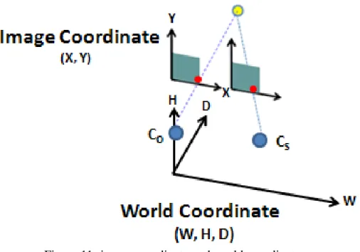
The rough stereoscopic model of the scene can be composed with the vanishing lines as shown in [11]. Two vanishing lines could construct a plane. For example, the main vanishing line would separate the vertical plane from the horizontal plane in the left and right cases (Fig. 9-a and 9-b). The stereoscopic space of the monocular video can be constructed by vertical and horizontal planes. The proposed algorithm is to transform the image coordinate into world coordinate based on the vanishing model which is constructed by vanishing point. The image coordinate and world coordinate is exhibited in Fig. 11, where CO and CS are the points of
original camera and synthesized camera, respectively.
There are two components in view synthesis, background view synthesis and foreground view synthesis. Background view synthesis utilizes the characteristic of static camera to warp the static background from background registration at first. And then, the position of the moving objects are calculated and attached to the static background in moving object synthesis.
- 16 -
Figure 11- image coordinate and world coordinate.
3.2 Background Projection
Before the introduction to the coordinates transform, there is a specific equation to describe. It is assumed that there are two points O1: (WO1, HO1, DO1) and O2: (WO2, HO2, DO2)
where HO1 equals HO2. The projected points of O1 and O2 on screen plane are P1: (WP1, HP1,
DP1) and P2: (WP2, HP2, DP2). The position of camera in world coordinate is CO: (0, hC, 0).
Because O1 is on the line COP1 and O2 is on the line COP2 , O1 and O2 could be
represented by (WP1t,(HP1hc)t,DP1t) and (WP1w,(HP1hc)w,DP1w) respectively, where
t and s is constant. When HP1 equals HP2, t is equal to s when HP1 and HP2 are not equal to hC.
Consequently, DO1 equals DO2. It means that the depth value of the two points which are both
on horizontal plane would be equal when their projected points on screen plane have the same height.
Based on the vanishing model, we transform the point (x,y) on the horizontal plane in screen coordinate into the width w and depth d in world coordinate by
- 17 -
) ( )) 2 )( 2 ( ( 2 y y f y H H y f h d vanish frame frame vanish C (1) 2 2 2 2 ) 2 ( ) 2 ( frame C frame H y f h d W x w (2)Where hC is the height from the horizontal plane to camera in world coordinate as
) 2 ( 2 * * 2 frame vanish frame vanish C H y H f y f L h , (3)
and yvanish is the value of y-axis of vanishing point, f is focal length of camera, L is the distance between camera to the bottom of screen in world coordinate, Wframe and Hframe are
the resolution of the video sequence. The derivations of equation (1), (2), and(3) are in the following.
Because vanishing point is the farthest in the vanishing model, the line from camera to vanishing point is parallel to the horizontal plane in world coordinate. When camera aims at the farthest, vanishing point is located at the middle of the screen, as shown in Fig 12-A. The vanishing point is below or above the middle of the frame if it aims at somewhere in the horizontal plane, as Fig. 12-B and 12-C respectively. In Fig. 12, V is the vanishing point in the screen, M is the middle of the screen, B is the bottom of screen, and the dotted line represents the screen plane.
- 18 -
(B)
(C)
Figure 12- The related position between vanishing point and the middle of screen when (A) camera aims at the farthest, (B) camera aims at the upper horizontal plane, (C) camera aims at
the lower horizontal plane.
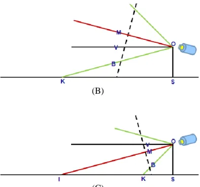
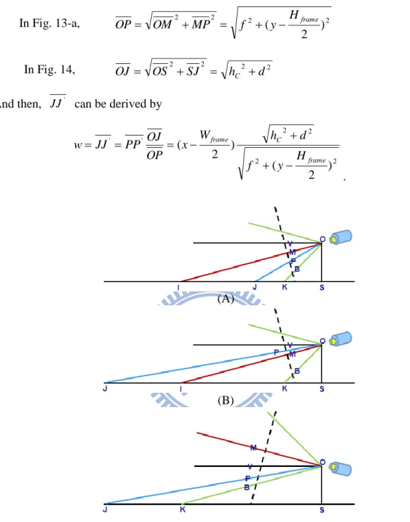
We take the case where camera aims at the lower horizontal plane as example. In Fig. 13-A, there are two points P and P’ in the screen. The relation of P and P’ is shown as in Fig. 14. The corresponding point of P’ on the horizontal plane is J’. The depth value d is SJ
when the point P’ is on the central line of the screen. However, every point with same value of y-axis which has the corresponding point on the same horizontal plane has the same depth value as the above-mentioned. We could calculate the depth value of P’ through estimating the depth value of the point P with the same value of y-axis on the central line of the screen. And the corresponding point of P on the horizontal plane is J.
Because of OJS is equal to JOV and JOV could be divided into VOM
and MOP, OJS is equal to VOM addition to POM . In the following derivation,
SO is hC, SJ is d , OM is the focal length f , and VMO and PMO are both
- 19 -
) ( )) 2 )( 2 ( ( * ) * ( ) ( ) * ( * * * * * * ) sin( ) sin( ) cos( ) cos( ) sin( ) cos( ) cos( ) sin( ) cos( ) sin( ) tan( ) tan( 2 2 2 2 2 y y f y H H y f h d PV f PM MV f h MV PM f PM MV f h d PM MV f PM f f MV PM MV OM PM OM OM MV d h POM VOM POM VOM POM VOM POM VOM d h POM VOM POM VOM d h POM VOM OJS vanish frame frame vanish C C C C C C (4)The aspect of derivation to hC is similar to equation (4). When the point P is equal to B, d
is equal to L. And then, equation (3) can be derived from equation (4).
In Fig. 13-B, the point P is located between V and M . The derivation is similar to Fig. 13-A except that PM in Fig. 13-A is positive but it is negative in Fig. 13-B. It represents POM is negative in Fig. 13-B. OJS is equal to subtraction ||MOP||
from ||VOM ||.
If the case is that camera aims at the upper horizontal plane, the derivation is also similar to (4). In Fig. 13-A, B, MV is positive but it is negative in Fig. 13-C. OJS is equal to
|| ||
||
||MOP VOM .
Since the case could not affect the transform equation as the above-mentioned, we take Fig. 13-A as an example without loss of generality.
The width w of J’ in world coordinate can be simply estimated through the theorem of similar triangle. In Fig. 14, JJ' would be calculated by the equalized ratio when we have known the value of OP, OJ , and PP'. But the information which we have known includes
SJ, OS and PP', which are d, hC, and
2
frame
W
x respectively. Before estimating the width, we have to transform these information by
- 20 -
In Fig. 13-a, 2 2 2 2 ) 2 (y Hframe f MP OM OP (5) In Fig. 14, 2 2 2 2 d h SJ OS OJ C (6)And then, JJ' can be derived by
2 2 2 2 ' ' ) 2 ( ) 2 ( frame C frame H y f d h W x OP OJ PP JJ w . (7) (A) (B) (C)
Figure 13- Illustrate the derivation to d and h with the point P located between (A) V and M, (B) M and B, at the case with camera aimed at the lower horizontal plane, (C) at the case with
- 21 -
Figure 14- Another viewpoint from Fig. 13-A for illustration.
The following is going to transform the point P: (x, y) on the vertical plane in image coordinate into depth d and width w in world coordinate. The fundamental idea is to search the corresponding foothold on the horizontal plane. The corresponding foothold is defined as the point with the same depth and the width as the point P on the horizontal plane. The depth and width of the corresponding foothold can be derived from equation (1), (2).
In the world coordinate, the screen plane equation is assumed as
ah+bd=c (8)
Where a, b, and c are constant. In Fig. 15, it is assumed that there are two points p1: (Wp1, Hp1,
Dp1) and f1: (Wf1, Hf1, Df1) in world coordinate, where Hp1 is not equal to Hf1 but Wp1 equals
Wf1 and Dp1 equals Df1. p1 is the corresponding point in the world coordinate that projects to
the point (x,y) in the image coordinate. The projected points on the screen plane is p2:
(Wp1*t, (Hp1-hC)*t, Dp1*t) and f2: (Wf1*s, (Hf1-hC)*s, Df1*s) respectively, where s and t is
constant. By the equation
[aHp1-ahC+bDp1]*t = [aHp2-ahC+bDf1]*s = c. (9)
Only if Wp1 is zero or a is zero, the width on the screen plane of these points is the same.
It means that the projected points of p1 and f1 on the screen plane have the same width in
world coordinate (or the same value of x-axis in image coordinate) when the projected point p2 of p1 is located at the central line
- 22 -
ah+bd=c, w=0 (10)
or camera aims at vanishing point as Fig. 12-A. At these cases, the corresponding foothold can be found by intersecting the line (ah+bd=c, w=Wp1*t) which has the same width with the
corresponding point with the vanishing line separating vertical and horizontal planes.
Otherwise, for the case that Wp1 is not zero and a is not zero, we need to find the line p2 f2
on the screen plane.
In Fig. 15, it is assumed that there are four points, p3: (0, (Hp1-hC)*t, Dp1*t) and f3: (0,
(Hf1-hC)*s, Df1*s) on the central line of equation (10), p4: (0, (Hp1-hC)*t, 0) and f4: (0,
(Hf1-hC)*s, 0). By the derivation, 2 1 2 1 1 2 1 2 1 2 1 2 1 2 1 2 1 1 1 1 1 2 4 3 4 2 4 3 4 2 4 3 * ) * ( ) * ( ) * ( * ) * ( ) * , 0 , * ( ) * , 0 , 0 ( * ) cos( p p p p p p p p p p p p p D W D D W t D t D t D t W t D t D t W t D p p p p p p p p p p p (11) 2 1 2 1 1 2 1 2 1 2 1 2 1 2 1 2 1 1 1 1 1 2 4 3 4 2 4 3 4 2 4 3 * ) * ( ) * ( ) * ( * ) * ( ) * , 0 , * ( ) * , 0 , 0 ( * ) cos( f f f f f f f f f f f f f D W D D W s D s D s D s W s D s D s W s D f f f f f f f f f f f (12)
Since Wp1 equals Wf1 and Dp1 equals Df1, cos(p3p4p2) is equal to cos(f3f4f2). Because
not only p3p4p2 is equal to f3f4f2 but also p2p3p4 and f2f3f4 are both right
angle, p2p3p4 and f2f3f4 are similar triangles. Therefore, f3f2 can be derived when 3
4f
- 23 -
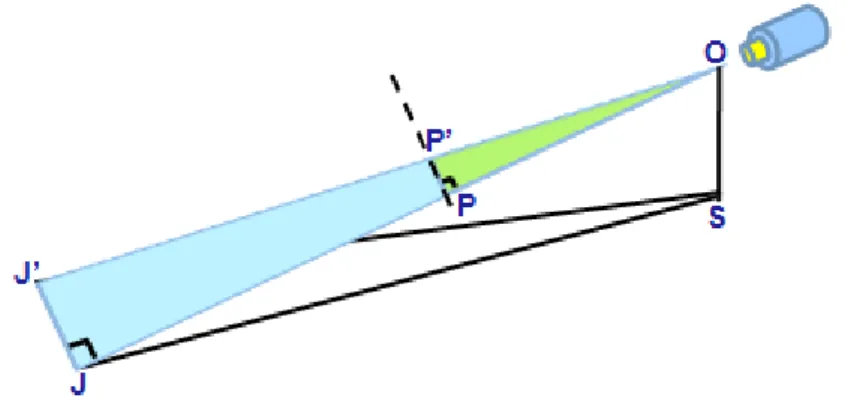
the screen plane which is PM in Fig. 16, and OM is equal to f . 2 2 3 frame W x p p (13) ) sin( 3 3 3 4p OC OV VC OV Vp CpV p V Cp3
is similar to MOV , Cp3V is equal to MOV
2 2 2 2 3 4 3 3 3 4 ) 2 ( ) 2 ( ) ( ) 2 ( ) sin( vanish vanish vanish vanish y H f y H y y y H f p p OV MV Vp OV MOV Vp OV p p (14) V or M could be considered as f3: V f3 , ) 2 )( ( ] ) 2 ( [ ] ) 2 ( )[ ( ) 2 ( 2 2 2 2 3 4 2 3 3 4 2 3 2 2 3 4 vanish frame vanish vanish frame vanish frame vanish vanish frame y H y y y H f y H f y y p p p p f f f f y H f OV f f (15) M f3 , ) 2 )( ( ] ) 2 ( [ ) ( ) 2 ( ) cos( 2 2 2 3 4 2 3 3 4 2 3 2 2 2 3 4 vanish frame vanish vanish frame vanish vanish frame y H y y y H f y y f p p p p f f f f y H f f MOV OM f f (16)
And then, the required line would be found by linking p2 and f2 on the screen plane.
The corresponding foothold would be found by intersecting the line to the bound of the horizontal plane. The corresponding foothold in image coordinate could be transformed into depth and width in world coordinate by equation (1)(2). Finally, we have gotten the width w
- 24 -
coordinate.
Figure 15- Illustration for the relation between p3p2 and f3f2.
(A)
- 25 -
(C)
Figure 16- The cross-sectional view on plane w=0 from Fig. 15.
3.3 Moving Object Projection
There is much less information of moving objects from monocular video compared to the multiview videos. Therefore, the inaccuracy of moving object synthesis is expectable. In [5], they classify the moving objects as the nearest part to the camera to construct the depth map, and assign all the moving objects one depth value. The moving objects would have the same depth value in depth map even if there is some depth variation between frames. How to make the result of moving object synthesis smooth and obtain reasonable depth variation is the focus of our proposed method.
Because the initial depth value could not be estimated accurately when the moving objects don’t have the same motion magnitude in the real world, we would set the initial depth value of the moving objects manually to show the effect of depth update.
In our proposed method, we estimate the depth value by the magnitude and direction of objects’ motion. To improve the accuracy of moving object synthesis, we make the assumption that the magnitude of objects’ motion would be large when they are located nearer from camera, and the magnitude of objects’ motion would be small when they are located farther from camera. It is derived from the work [12]. In [12], Karl mentioned that the retinal images of objects close to the eye are displaced more quickly than the retinal images of more distant objects. And then, we could estimate the initial depth value is estimated by the
- 26 -
magnitude of objects’ motion.
Before we introduce the initial depth value from motion, the following would describe the motion estimation of the moving objects. Instead of estimating motion of all the pixels of moving objects, we only take motion estimation on the pixels which are located at the boundary of moving objects. Because it may be similar between the pixels in the inner scope of moving objects, it could mislead the motion estimation. However, there is less possibility when estimating motion of the pixels on the boundary. The light would change the color of the pixels on the boundary to make them distinguished.
After motion estimation, the average of motion vectors would be considered as the representation of this moving object. The magnitude of the motion vector is utilized to estimate the initial depth value by
farthest d mag mag max max max2 2 , (17)
where mag is the magnitude of the average of motion vectors, max is the maximum magnitude of motion vector, and dfarthest is the farthest depth value on the horizontal plane.
farthest
d mag
max max
is to map the magnitude of motion vector to depth linearly, while
2 2
max
mag
makes the estimated depth value more sensitive when the magnitude is large.
But there may be some unreasonable depth values, for example, the position of moving objects is much nearer than the estimated depth value. At that time, the initial depth value would be set by the bottom of moving objects. It means that the bottom of moving objects is considered as the foothold.
After the initial depth value is estimated at the frame where the object is appeared at the first time, the depth value of the object at the later frame would inherit and modify the information from the previous depth value for the smoothness purpose of motion vector. The motion vector of the objects could be utilized to vary the depth value.
- 27 -
We transform the previous depth value from the world coordinate to the y value of the image coordinate by equation (1) at first. And then, the point on the screen plane would be considered as the foothold even if it may be out of the resolution of frame. Because the foothold of the object is one of the points of object, it is suitable to use the motion vector to move. The moved foothold could be transformed from the image coordinate to the world coordinate again.
Finally, the estimation of the depth value not only inherits the previous value from the previous depth value but also can be updated by the averaged motion vector. Because the inheritance of depth value, we could avoid the jitter which is caused from the estimation only by the magnitude of motion. And the utilization of averaged motion vector results in the reasonable depth variation instead of the steady depth as in [5]
3.4 View Synthesis
.After the conversion from the image coordinate into the world coordinate, the following is to shift the world coordinate along the width-axis at another view point. Because of the horizontal shift, the value of y-axis would be the same. We can derive the synthesized value of x-axis of the points on the horizontal plane by operating the equation (2) backwardly. However, the synthesized value of x-axis of the points on the vertical plane and the moving objects could be converted into the image coordinate more easily.
Similar to Fig. 15, because we have known the varied width and depth of p1: (Wp1, Hp1,
Dp1)=(w’, Hp1, d), we can assume two points p5: (0, Hp1, d) and p6: (0, Hp1, 0). Similar to
equation (11) and (12), cos(p3p4p2) equals cos(p5p6p1) and p2p3p4 and
6 5 1p p
p
are both right angles. So, p2p3p4 and p1p5p6 are similar triangles.
- 28 -
3 4 3 4 5 6 1 5 2 3 ' p p d w p p p p p p p p . (18)By equation (14), we could derive p4p3. Finally, by equation (13),
2 2 3 frame W p p x . (19)
- 29 -
Chapter 4.
EXPERIMENT RESULT
In this chapter, we would exhibit the results in [4], [5], and [6] for comparison at the first section. At the second section, there are three video sequences, camera 5 of lovebird1, camera 7 of Alt Moabit, and homemade video hallway, to be used to synthesize the stereoscopic views. We would exhibit the original view, the synthesized view, and the depth map for subjective results. To represent the stereoscopic effect, we would compose a red-cyan anaglyph of the original view and the synthesized view. And then, the synthesized videos from lovebird1 and Alt Moabit would compare to the ground truth objectively in PSNR.
4.1 Related Results
4.1.1 Stereoscopic Video Synthesis from a Monocular Video [4]
Zhang et al. proposed three steps to synthesize stereoscopic video from monocular one. They tracked the camera motion by a camera-tracking algorithm at first. And then, a
- 30 -
(A)
(B)
Figure 17- An example of stereoscopic video generation.
The input monocular video is taken in the air. (A) shows the recovered base trajectory and a few frames from the base sequence. (B) shows the composed stereo frame [4].
4.1.2 Depth Map Generation for 2D-to-3D Conversion by
Short-Term Motion Assisted Color Segmentation [5]
Chang et al. propose an algorithm to combine the motion segmentation and color segmentation for conversion the depth map. They assign the detected foreground as the
- 31 -
nearest and assign the other as the farthest.
(A) (B)
(C) (D)
(E) (F)
Figure 18- Subjective view results
(A) Original Akko & Kayo sequence (B) The depth map of Akko & Kayo (C) Original
Children sequence (D) The depth map of Children (E) Original Weather sequence (F) The
- 32 -
4.1.3 3D Stereoscopic Image Pairs by Depth-Map Generation [6]
Battiato et al. estimate the depth map by the depth gradient constructed by vanishing lines. And then, utilize the work in [13] to assign the sky as the farthest.
(A) (B)
(C) (D)
- 33 -
Figure 19- (A) Original outdoor with geometric appearances image (B) Geometric depth map (C) Qualitative depth map through [12] (D) Final depth map (E) Anaglyph image [6].
4.2 Results of Proposed Method
4.2.1 Subjective Results
In lovebird1 video, the moving objects move closer and closer. Fig. 20 is the previous frame of Fig. 21. The gray level of the moving object is 175 in Fig. 20-C and the gray level of the one is 185 in Fig 21-C. It shows the depth would vary with the position of the moving object. Because the distance between two eyes is so close, it is difficult to distinguish the difference between the original view and the synthesized view. We adopt the red-cyan anaglyph to exhibit the stereoscopic effect and make the variation more differentiable in human vision.
- 34 -
(C)
(D)
Figure 20- the camera 5 of lovebird1 (A) The original view, (B) The synthesized view, (C) The depth map of (A), (D) Red-cyan anaglyph.
- 35 -
(C)
(D)
Figure 21- another view of the camera 5 of lovebird1 (A) The original view, (B) The synthesized view, (C) The depth map of (A), (D) Red-cyan anaglyph.
In Fig. 22-C, the gray level of the walker is 154 and the gray level of the bus is 204. Although the absolute depth value may be not accurate, it could distinguish the related depth between the objects.
- 36 -
(A) (B)
(C)
(D)
Figure 22- Camera 7 of Alt Moabit (A) The original view, (B) The synthesized view, (C) The depth map of (A), (D) Red-cyan anaglyph.
- 37 -
(A) (B)
(C)
(D)
- 38 -
map of (A), (D) Red-cyan anaglyph.
4.2.2 Subjective Result of Predefined Initial Depth Value
We would set the initial depth value of the moving objects manually. Under the manual initial depth value, the depth map would combine the depth of background and the depth of the moving objects. And then, the effect of depth update would be judged more easily. In Fig 24-A, the initial depth value is assigned. And then, the depth value of the person after depth update is also similar to its foothold in Fig 24-B, C. It represents that the depth update is reliable when the initial depth value is accurate; otherwise, the depth update is relative accurate.
- 39 -
(B)
(C)
Figure 24- the depth map of manual initial depth value. (A) The frame #1 of Alt Moabit, (B) The frame #40 of Alt Moabit, (C) The frame #60 of Alt Moabit.
4.2.3 Objective Results
In this section, we would compare the synthesized view to the ground truth from the multiview video sequences. In Fig. 25, the synthesized video is camera 6 of lovebird1.
- 40 -
According to the intrinsic parameter of camera, we set the focal length to 2017.8074. And then, set the distance between camera 5 and camera 6 to 38.66 by translation parameter. Although the inaccuracy of moving object could influence the result, the quality of the background view synthesis is kept to the average value 27.93 in PSNR.
For the blue line, it is the synthesized from camera 5 and camera 8 of lovebird1 by the tool of multiview synthesis VSRS [3]. However, it needs to be preprocessed to estimate the depth map [1] from the left and right view as shown in Fig. 2. So, there are six views to be used to estimate and synthesize to the virtual one. The average of PSNR from the proposed method from the monocular video is only lower than the average of PSNR from multiview synthesis by about 3 to 4 dB.
Figure 25- Synthesize the camera 6 of lovebird1 from single view and multiview synthesis. The red line is synthesized by VSRS, and the blue line is synthesized by the proposed method.
The average of red line in PSNR is 31.88, and the average of blue line in PSNR is 27.93.
In Fig. 26, the synthesized video is camera 8 of Alt Moabit. For the red line, it is synthesized from camera 7 of Alt Moabit. The focal length and the distance between camera 7 and camera 8 are set by camera parameter to 1382.4 and 62.05 respectively. In this video, the
- 41 -
quality of the synthesized video is unsteady. The chief influence of PSNR is the misses of moving object detection. Since there are some moving objects with large size in video, the misses of the object would decrease the value of PSNR substantially. In frame number 36, the big bus is moving in the frame. The transparent windows of the bus would mislead the moving object detection. These windows are classified as the static background, so that the value of PSNR decreases substantially from frame number 36. However, except for that, the quality in PSNR is kept at about 29.44.
For the blue line, it is synthesized from camera 7 and camera 10 of Alt Moabit by the tool of multiview synthesis VSRS [3]. There are six views to be used to estimate and synthesize to the virtual one as the above-mentioned. The average of PSNR from the proposed method from monocular is only lower than the average of PSNR from multiview synthesis by about 4dB.
Figure 26- Synthesize camera 8 of Alt Moabit from single view and mutiview synthesis. The red line is synthesized by VSRS, and the blue line is synthesized by the proposed method.
- 42 -
Chapter 5.
CONCLUSION
5.1 Conclusion
In this study, we propose the transform algorithms to synthesize stereoscopic view from monocular video. The fundamental idea is based on the stereoscopic model constructed by vanishing point. Therefore, the preprocessing steps are necessary before view synthesis.
To improve the effect of moving object detection, we make some modification from [8]. The improvement of modification is shown in Fig. 6. The result of background registration has been promoted. Another preprocessing step is vanishing point dectection. We adopt the algorithm in [6] to search the vanishing lines and vanishing point.
In view synthesis, there are two partitions: background projection and moving object projection. The effect of the proposed transforming algorithms could be shown in subjective method, which exhibits the stereoscopic effect by constructing the red-cyan anaglyph, and be shown in objective method, which compares the synthesized view with the ground truth in PSNR. It is different with other works of view synthesis from single view. Although the value of PSNR is lower than the synthesized view from multiview, the synthesized view of the proposed method could keep the difference of PSNR within about 3 to 4 dB even if there is much less information in monocular video than multiview ones.
The proposed method provides novel transforming algorithms and the results could be compared in objective and subjective method instead of only compared by subjective results.
- 43 -
REFERENCES
[1] Masayuki Tanimoto, Toshiaki Fujii, Kazuyoshi Suzuki, “Multi-view depth map of Rena and Akko & Kayo”, ISO/IEC JTC1/SC29/WG11, M14888, 2008.
[2] Masayuki Tanimoto, Toshiaki Fujii, Kazuyoshi Suzuki, “Experiment of view synthesis using multi-view depth”, ISO/IEC JTC1/SC29/WG11, M14889, 2008.
[3] Cheon Lee, Yo-Sung Ho, “View Synthesis Tools for 3D Video”, ISO/IEC JTC1/SC29/WG11, M15851, 2008.
[4] Guofeng Zhang, Wei Hua, Xueying Qin, Tien-Tsin Wong, and Hujun Bao, “Stereoscopic Video Synthesis from a Monocular Video”, IEEE Transactions on Visualization and Computer Graphics, Vol. 13. No. 4, 2007.
[5] Yu-Lin Chang, Chih-Ying Fang, Li-Fu Ding, Shao-Yi Chen, and Liang-Gee Chen, “Depth Map Generation for 2D-to-3D Conversion by Short-Term Motion Assisted Color Segmentation”, IEEE International Conference on Multimedia and Expo, pp. 1958-1961, 2007
[6] S. Battiato, A. Capra, S. Curti, M. La Cascia, “3D Stereoscopic Image Pairs by
Depth-Map Generation”, Proceedings of the 2nd International Symposium on 3D Data Processing, Visualization, and Transmission, pp. 124-131, 2004
[7] Shao-Yi Chien, Yu-Wen Huang, Bing-Yu Hsieh, Shyh-Yih Ma, and Liang-Gee Chen, “Fast Video Segmentation Algorithm With Shadow Cancellation, Global Motion
Compensation, and Adaptive Threshold Technique”, IEEE Transactions On Multimedia, Vol. 6, No. 5, October 2004.
[8] Shao-Yi Chien, Shyh-Yih Ma, and Liang-Gee Chen, “Efficient Moving Object
Segmentation Algorithm Using Background Registration Technique”, IEEE Transactions on Circuits and Systems for Video Technology, Vol. 12, No. 7, July 2002.
- 44 -
[9] Sohaib Khan, Mubarak Shah, “Object Based Segmentation of Video Using Color, Motion and Spatial Information”, IEEE Computer Society Conference on CVPR, pp. II -746-751, 2001.
[10] Andreas Krutz, Matthias Kunter, Mrinal Mandal, Michael Frater, “Motion-based Object Segmentation using Sprites and Anisotropic Diffusion”, Image Analysis for Multimedia Interactive Services, WIAMIS ’07 Eighth International Workshop on, pp. 35, 2007. [11] Youichi Horry, Ken-ichi Anjyo, Kiyoshi Arai, “Tour Into the Picture: Using a Spidery
Mesh Interface to Make Animation from a Single Image”, Proceedings of the 24th
annual conference on Computer graphics and interactive techniques, pp. 225-232, 1997.
[12] Karl Kral, “Sid-to-Side head movements to obtain motion depth cues: A short review of research on the praying mantis”, Behavioural Processes, Vol. 43, Issue 1, pp. 71-77, April 1998,
[13] D. Comaniciu, P. Meer, “Robust Analysis of Feature Spaces: Color Image Segmentation”, In Proc. of IEEE Conference on Computer Vision and Pattern Recognition, pp. 750-755, June 1997.