Global Elimination Algorithm and Architecture Design for Fast Block Matching
Motion Estimation
Yu-Wen Huang, Shao-Yi Chien, Bing-Yu Hsieh, and Liang-Gee Chen
Abstract—This paper presents a new block matching motion
estimation algorithm and its VLSI architecture design. The pro-posed global elimination algorithm (GEA) was derived from suc-cessive elimination algorithm (SEA), which can skip unnecessary sum of absolute difference (SAD) calculation by comparing min-imum SAD with subsampled SAD (SSAD). Our basic idea is to separate the decision of early termination and SAD calculation for each candidate block to make data flow more regular and suitable for hardware. In short, we first compare the rough characteristics of all candidate blocks with the current block (SSAD). In turn, we select several best roughly matched candidate blocks to re-com-pare them with the current block by using detailed characteristics (SAD). Other features of GEA include fixed processing cycles, no initial guess, and high video quality (almost the same as full search). Unlike other fast algorithms, the mapping of GEA to hardware is very simple. We proposed an architecture that is composed of a systolic part to efficiently compute SSAD, an adder tree to support both SSAD and SAD calculations, and a comparator tree to avoid expensive sorting circuits. Simulation results show that our design is much more area efficient than many full-search architectures while maintaining high video quality and processing capability.
Index Terms—Block matching, global elimination algorithm
(GEA), motion estimation (ME), successive elimination algorithm (SEA).
I. INTRODUCTION
M
OTION-COMPENSATED transform coding has beenadopted by all of the existing international standards related to video coding, such as the ISO MPEG series [1]–[3] and the ITU-T H.26x series [4]–[6]. Motion estimation (ME) removes temporal redundancy within frames and, thus, pro-vides coding systems with high compression ratio. Since an ME module is usually the most computationally intensive part in a typical video encoder (50%–90% of the entire system), efficient implementation of ME is a must. A block matching approach is mostly selected as the ME module in video codecs and is adopted in the standards because of its simplicity and good performance. Among all the block matching algorithms, full-search block matching algorithm (FSBMA) is the most popular but demands the most computation. Despite the huge
Manuscript received December 20, 2002; revised December 1, 2003. This paper was recommended by Associate Editor R. Chandramouli.
Y.-W. Huang and L.-G. Chen are with the DSP/IC Design Laboratory, Department of Electrical Engineering and Graduate Institute of Electronics Engineering, National Taiwan University, Taiwan, 10617 R.O.C (e-mail: [email protected]; [email protected]).
S.-Y. Chien was with the Graduate Institute of Electronics Engineering, National Taiwan University, Taiwan 10617, R.O.C. He is now with Quanta Computer Inc., Taoyuan, Taiwan, 10617 R.O.C. (e-mail: [email protected]).
B.-Y. Hsieh is with MediaTek Inc., Hsinchu, Taiwan, 10617 R.O.C. (e-mail: [email protected]).
Digital Object Identifier 10.1109/TCSVT.2004.828321
computation, e.g., 9.3 giga operations per second (GOPS)
for CIF 30 Hz with search range, many parallel
and pipelined VLSI architecture designs for FSBMA have been developed due to its regular data flow. In general, the processing capability of one-dimensional (1-D) systolic arrays is not high enough for real-time applications with large search range or large frame size, so the operating frequency has to be raised to hundreds of MHz. The processing capability of two-dimensional (2-D) systolic arrays is very high, but the number of processing elements (PE) is too large. As for the tree architecture, the main problem is the huge memory access. Thus, we decided to improve the ME design at the algorithmic level.
Many fast algorithms have been proposed to save the huge computation of FSBMA. One method is to reduce the search positions, such as three-step search [7], new three-step search [8], four-step search [9], 1-D full search [10], and diamond search [11]–[13]. Another way is to simplify the matching operations, such as pixel decimation [14], mini-max criterion [15], boundary match [16], and pixel truncation [17]. Nev-ertheless, these fast algorithms suffer for considerable peak signal-to-noise ratio (PSNR) degradation compared to FSBMA, especially when the motion field is large and complex.
Recently, fast full-search block matching algorithms, such as successive elimination algorithm (SEA) [18]–[20], partial dis-tortion elimination (PDE) [21], and winner-update algorithm [22], have come into notice for their capabilities to reduce the heavy computation of FSBMA and to maintain the same results as FSBMA simultaneously. However, they were not developed with hardware considerations and are only suitable for software implementation. SEA avoids unnecessary sum of absolute dif-ference (SAD) calculations by comparing an up-to-date min-imum SAD with the absolute difference between the sum of pixels in current block and sum of pixels in candidate block, or namely subsampled SAD (SSAD). The total execution time will be reduced if many SAD calculations are skipped. Hence, it is critical for SEA to find good initial guesses of motion vec-tors (MVs) with smaller SADs in the early stage to increase the skipping ratio, but this is a difficult task for the regions where the motion field is not smooth. Moreover, the irregular data flow of SEA makes the systolic mapping to hardware a very tough task. In this paper, we modified the SEA and proposed a new block matching algorithm called global elimination algorithm (GEA). In contrast to SEA, the conditional branch when a candidate block cannot satisfy the criterion of early termination is removed, the data flow is more regular, the processing cycles are fixed, and no initial guess is needed. Experimental results show that GEA can achieve almost the same results as FSBMA. Furthermore, the most important feature of GEA is
that it is very easy to design. We also proposed an efficient VLSI architecture design for GEA. The core consists of a systolic part, a parallel adder tree, and a parallel comparator tree. Compared to many existing FSBMA architectures, our design is much more area-efficient.
The rest of the paper will be organized as follows. In Sec-tion II, we will review SEA and describe our GEA. Next, our GEA architecture will be presented in Section III. Section IV is the comparison of our design and FSBMA architectures. Fi-nally, Section V gives a conclusion.
II. ALGORITHMS
Usually, the block matching process is performed only on the luminance frame. Each luminance frame is divided into blocks of size , and each block in the current frame is matched with candidate blocks of size within the search area in the reference frame. The best matched block has the lowest SAD among all of the candidate blocks. Instead of the original block, the displacement (motion vector) of the best matched block and the prediction residue will be transmitted to the decoder.
A. Full-Search Block Matching Algorithm
FSBMA can be described by the following equations:
(1) (2)
where denotes the SAD at search position
is in the range of
means current block data, stands for search area data, the block size is , the search range
is , and expresses the motion vector of current
block with minimum SAD among search positions.
B. SEA
The main idea of SEA [18] can be shown in the following inequality:
where , and
. To compute sea is much easier than to compute SAD due to the fact that is the sum of pixels in current block and only has to be calculated one
time, and the sum of pixels in candidate block at
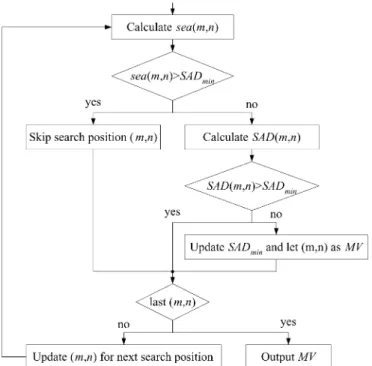
Fig. 1. Flowchart of SEA.
search position can be derived from the previous value
of as follows:
(3)
If is larger than current minimum SAD, denoted by
, it is guaranteed by inequality (3) that will be larger than , and, thus, the search position can be skipped. Otherwise, still needs to be calcu-lated and compared with . It is clear that a good initial guess of MV with small SAD is critical for SEA to increase the skipping ratio. Therefore, it is common to further speed up SEA with the use of MV predictors or spiral scan order of search po-sitions. The flowchart of SEA is summarized in Fig. 1. A con-ditional branch exists after sea calculation for each search po-sition, which makes the data flow irregular and unfavorable for hardware.
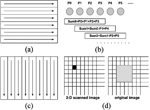
Another faster way to compute is the frame-based method stated in [22]. An example with is shown in Fig. 2. The first step is the horizontal scanning process on the original image, as shown in Fig. 2(a). A window of length is placed at each position by raster scan order. The pixels in the window are summed, and the result is stored in the horizontally scanned image. Besides, efficient reuse of the previous result can be easily achieved, as shown in Fig. 2(b). The second step is the vertical scanning process on the horizontally scanned image, as shown in Fig. 2(c). The process is similar to the horizontal scanning, and the result is stored in the vertically scanned image.
Fig. 2. Illustration of frame-based calculation for sum of 42 4 candidate block, SB(m; n). (a) Horizontal scanning process. (b) Example of data reuse for a row. (c) Vertical scanning process. (d) Marked pixel in the 2-D scanned image is equal to sum of pixels in the 42 4 block (painted in gray) in the original image.
Eventually, each intensity value in the 2-D scanned image cor-responds to the sum of pixels in a block of size , as illus-trated in Fig. 2(d). Although the frame-based method is much faster, it requires a frame memory and is not suitable for hardware.
C. Multilevel SEA
Multilevel SEA (MSEA) [19], [20] changes the value in Fig. 1 to value. Let us modify inequality (3) to form the following inequality:
(4) In inequality (4), a block of size is divided into nonoverlapping subblocks, is the sum of the th subblock in current block, and is the sum of the th subblock in candidate block at search position . For each search position, is calculated to decide if the SAD
calcu-lation can be skipped or not. When is reduced
to and is called at level 1. If the subblocks are of the
same size and it is called at level
respectively. Fig. 3 illustrates at level 3 with . In general, the skipping ratio of MSEA is higher than that of SEA,
Fig. 3. Illustration ofmsea at level 3 with N = 16.
but to get the value requires more computation than sea. In fact, both and can be regarded as SAD with reduced number of pixels. There is only one “macro-pixel” in a mac-roblock for SEA. For and MSEA at level 3, there are sixteen “macro-pixels” in a macroblock. In the rest of this paper,
we denote and as SSAD . For
with denotes , and SSAD with is
ex-actly the same as SAD.
D. GEA
The data flow of SEA or MSEA is not regular due to the conditional branches after SSAD calculation to deter-mine the skipping process. This makes hardware design a tough task. Furthermore, when true MVs are beyond the search range, good initial guesses can never be found, and the skipping ratio could be so low that the processing time of SEA or MSEA is even longer than that of FSBMA. In
Fig. 4. Flowchart of GEA.
our GEA, these problems can be solved. The steps of GEA are shown in Fig. 4 and can be described in (5). Note that
denotes the sorted result of .
(5) Global elimination of search positions, which is described by step 2), is done after all SSAD values are calculated. No condi-tional branch is required within the calculation of SSAD at every search position. Consequently, the control of GEA is easier than SEA or MSEA. The result of GEA will be the same as FSBMA when the SSAD of the search position at which the smallest SAD is located is smaller than . Therefore, larger makes the results more reliable while smaller saves more computation. Generally speaking, the parameter provides an easy tradeoff between speed and coding gain. No matter what will be, the processing cycles can be fixed as long as is de-termined, which is also a good feature for hardware scheduling. Moreover, the processing speed is independent of scan order. Raster scan, which is easier to implement than spiral scan, can be chosen for GEA without sacrifice of processing speed.
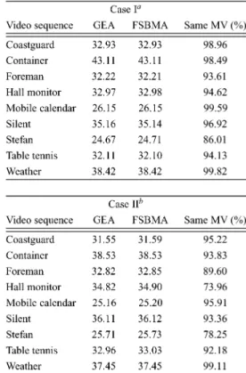
We use different values of and under two typical cases. The first case has the following parameters: ,
QCIF frame size search range. The
parameters of the second case are , CIF frame size search range. The results of Stefan are shown in Table I. As you can see, if we increase and step by step, the video quality will become better and better. However, the improvement of video quality by increasing and will stop when the video quality is already very close to full search. Further increase in and may result in waste of computation. According to our experiments, we
sug-gest to choose and for QCIF and CIF size
images.
E. Comparison and Analysis
After and are selected, we compare GEA to
FSBMA. Many standard sequences were tested. The results are shown in Table II. The average PSNR of motion compensated frames obtained by GEA is very close to FSBMA. Sometimes, GEA even results in a little higher PSNR values. Note that
TABLE I
AVERAGEPSNROFCOMPENSATEDFRAMES IN DB ANDSTEFAN
TABLE II
AVERAGEPSNROFCOMPENSATEDFRAMES IN DB AND THEPERCENTAGE OFSAMEMVs
minimum SAD does not always lead to minimum mean square
error, e.g., , but . The maximum
PSNR drop is only 0.08 dB (Hall monitor in Case II). The percentages of the same MVs found by both GEA and FSBMA are also listed. It is shown that GEA and FSBMA usually produce the same MVs. For Hall monitor and Stefan in Case
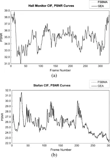
Fig. 5. PSNR versus frame. (a) Hall monitor in Case II. (b) Stefan in Case II.
TABLE III
RUNTIME OFVARIOUSME ALGORITHMS INMILLISECONDS
II, the moving objects are small, and the motion is large and complex, which leads to lower percentages of the same MVs. Even so, the PSNR drop is still insignificant, as shown in Fig. 5. Therefore, we claim that although GEA does not guarantee the same results as FSBMA, GEA is very reliable.
Table III summarizes the runtime profiles of various ME gorithms. Except for GEA and Diamond, all the other fast
al-gorithms are categorized as the fast full search, but note that GEA produces almost the same results while Diamond search suffers considerable PSNR degradation. The platform is a per-sonal computer with 866-MHz CPU, and the program codes are written in C . The speed of GEA is about the same as MSEA and is significantly faster than other fast full-search al-gorithms. Note that spiral scan of search positions is adopted for (M)SEA and PDE to achieve such fast speeds, while GEA uses raster scan. Besides, the speed of MSEA varies a lot for different scenes. For example, MSEA is faster than GEA on average. However, when the motion field is large and complex, e.g., in Stefan, the skipping ratio of MSEA is not high enough to de-feat GEA. Diamond search, which is recommended by MPEG-4 due to its average good performance, is four times faster than GEA. However, it cannot guarantee the video quality. The PSNR drops of GEA compared to FSBMA are only 0, 0.01, 0.04, and 0.01 dB for the four listed sequences in Table III, respec-tively. As for Diamond search, the drops are 0.04, 0.49, 1.29, and 0.43 dB, which may cause up to 30% of increase in bit rate. In sum, GEA regularizes the data flow of SEA by moving the SAD calculations behind all SSAD calculations. No initial guess or special scan order is required. The processing cycles are fixed. It is easy to make a tradeoff between the processing speed and the video quality by adjusting the value of . GEA can produce almost the same results as FSBMA, and the speed of software implementation is about the same as spiral MSEA. Most important of all, the hardware mapping of GEA is very simple. We will show this in the next section.
III. ARCHITECTUREDESIGNBASED ONGEA
We will choose , and
as an example to explain our architecture. The core of our architecture can be divided into three main parts: the systolic part, the parallel adder tree, and the parallel comparator tree.
A. Systolic Part
The data flow of the systolic part, which is to calculate the sum of pixels in a 4 4 subblock, is shown in Fig. 6. Note that
and denotes and in (1), respectively, and
the rectangles stand for shift registers. A column of block data is loaded in parallel at each clock cycle, denoted by . When data are loaded. The sum of pixels of each
sub-block in current sub-block, depicted as in Fig. 3,
is computed in parallel at and stored into registers.
Next, data are loaded column by column. When – ,
data of search positions – are loaded,
the sum of pixels of each subblock in candidate block, denoted
as in Fig. 3, will be available at – for
search positions – , respectively. Then,
columns of data for search positions –
are loaded in parallel at – and vice versa. Thus, it
takes clock cycles for a macroblock to
load all the data into the systolic part.
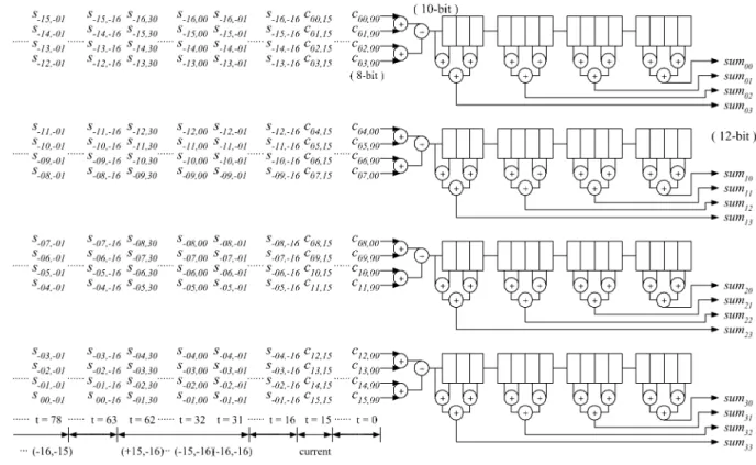
B. Parallel Adder Tree
The first purpose of the parallel adder tree is to com-pute SSAD. In Fig. 7, ADxx takes charge of the
computa-Fig. 6. Data flow of systolic part. Columns of block data are loaded in parallel, and the sums of subblockssum –sum are computed in parallel as well.
Fig. 7. Parallel adder tree calculates theSSAD(msea) value shown in Fig. 3. It can be reused to compute SAD of the M candidate blocks having smallest SSADs.
tion of absolute difference between and
de-noted in Fig. 3. The parallel adder tree adds the results from AD00–AD33 and outputs SSAD value. The second purpose is to compute SAD after the candidate blocks have been found by the parallel comparator tree, which will be described in the next subsection. SAD of 16 pixels can be calculated in one clock cycle, and the partial results are accumulated in another register. Thus, it requires clock cycles to compute the SAD of a candidate block.
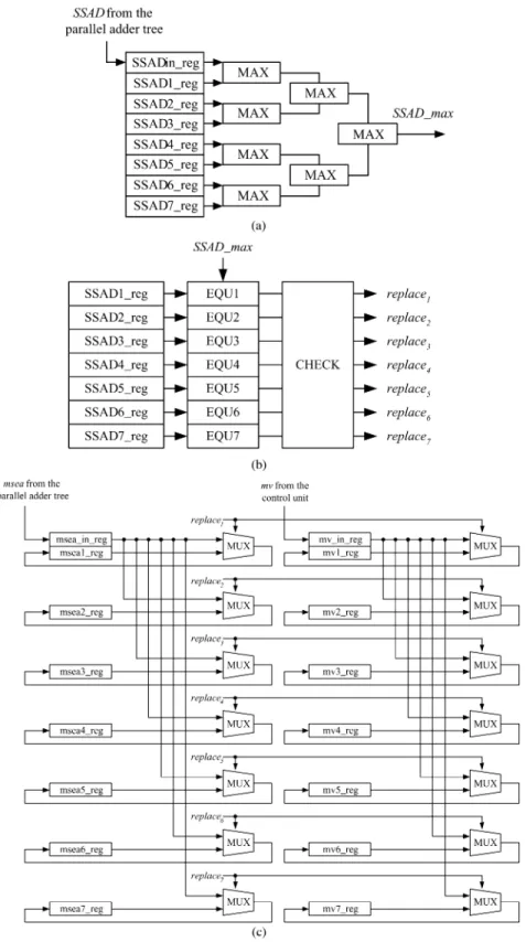
C. Parallel Comparator Tree
The objective of parallel comparator tree is to find the search positions that have the smallest SSAD values. The idea is to save the up-to-date smallest SSAD values and their cor-responding MVs in the registers. In turn, we compare the new coming SSAD of the next search position with the stored values and find the maximum among them. If the new coming SSAD is larger than the stored values, nothing will happen. If the maximum is one of the stored SSAD values, the largest one
and its corresponding MV will be replaced by the new SSAD and the new MV. If more than one of the stored SSAD values are equal to the maximum, only one of them and its MV will be replaced. In this way, we do not need sorting circuits, which is very expensive in chip area, to find the smallest SSAD values.
The comparator tree is divided into a forward part, as shown in Fig. 8(a), and two feedback parts, as shown in Fig. 8(b) and (c). Note that the symbols with “ reg” are registers. In Fig. 8(a), SSAD1 reg-SSAD7 reg should be properly initialized as 0xFFFF before the first valid value comes from parallel adder tree to SSAD in reg. The maximum value among the
eight values, denoted as , is computed
by the forward part. In Fig. 8(b), EQUx compares whether
SSADx reg equals to or not. If SSADx reg equals
to , EQUx will be activated; otherwise, it will be inactivated. The CHECK module functions as follows. If no EQU is active, no will be active. If only one EQUx is active, only the will be active. If more than one
Fig. 8. Parallel comparator tree. (a) Forward part to computeSSAD max. (b) One feedback part to find the target SSADx reg that will be replaced. (c) The other feedback part to replace the SSADx reg and mvx reg with SSAD in reg and mv in reg, respectively.
EQU units are active, only one of the corresponding
signal can be activated. For instance, when EQU1 and EQU2 are both active, only replace1 will be activated. In Fig. 8(c), if is active, SSADx reg and mvx reg will be replaced by the current values in SSAD in reg and mv in reg, respec-tively. Moreover, as shown in Fig. 6, invalid values
are generated periodically during the first cycles of loading data on every row of the search positions. At these cycles, the s inputted to the parallel comparator tree must be replaced by 0xFFFF. In sum, the parallel comparator tree is to keep the smallest values and their MVs in SSADx reg and mvx reg registers, respectively.
Fig. 9. Overall architecture design for GEA.
TABLE IV
COMPARISON OFVARIOUSME ARCHITECTURESWITHN = 16; p = 16; Level = 3, and M = 7
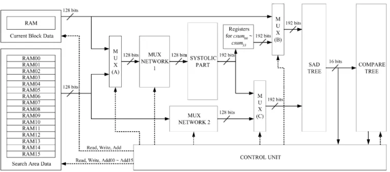
D. Overall Architecture Design
Fig. 9 presents the block diagram of the complete GEA archi-tecture. Besides the three core modules mentioned above (SYS-TOLIC PART, SAD TREE, and COMPARE TREE), there are still some control circuits (CONTROL UNIT, MUX, and MUX NETWORK ) and memory modules to store current block data and search area data. Note that the solid arrows denote the data signals, and the dotted arrows denote the control signals. In order to output a column of block data in parallel, 16 on-chip SRAM modules are required.
In brief, the architecture design of GEA is very simple. The
proposed hardware requires clock cycles
to find the search positions with the smallest values, and clock cycles are needed for the SAD calculation of the candidate blocks. Therefore, our GEA architecture in total
spends clock cycles to obtain the
MV of a macroblock. If we want to eliminate the bubble cycles of SSAD calculations during the beginning cycles at change of rows, we can use ping-pong mode systolic registers to store sums of 1 4 pixels. In this way, 32 on-chip SRAM modules are required to output the 32 pixels in parallel, and the
number of total cycles required for a macroblock is reduced to .
IV. ARCHITECTURECOMPARISON, DISCUSSIONS,AND
CHIPIMPLEMENTATION
A. Comparison Between GEA Architecture and FSBMA Architectures
In this subsection, we compare our design with many archi-tectures based on FSBMA. The results of two typical cases are shown in Tables IV and V. Only the PE arrays of the FSBMA ar-chitectures were implemented for comparison because the con-trol unit only occupies a very small part of the whole design. In Tables IV and V, architectures labeled with “*” symbol need many additional shift registers to reuse data, but these regis-ters were not implemented. The real gate counts of these de-signs would be higher than the reported results. As for our GEA architecture, all the parts in Fig. 9 except for RAM modules were included in the simulation. Note that all designs have to save current block data and search area data, so the required number of bits for on-chip SRAM is the same for all designs.
TABLE V
COMPARISON OFVARIOUSME ARCHITECTURESWITHN = 16; p = 32; Level = 3,ANDM = 7
The VLSI circuits were described in Verilog HDL and synthe-sized by SYNOPSYS Design Analyzer using AVANT! 0.35-m cell library. In order to be fair, the co0.35-mparison was 0.35-made under the same throughput of MVs (number of estimated MVs per second). Consequently, we first estimated the required op-erating frequency of each architecture for the real-time applica-tion of 30 CIF f/s. In turn, proper pipeline registers were added and the critical path constraints were set to just meet the target speeds.
In general, the processing capability of the 1-D arrays is not high enough. The operating frequency for applications with large frame size and large search range has to be substantially increased to an unacceptable extent. The processing capability of the 2-D arrays is very high, but the enormous gate count makes them expensive. The architecture in [28] belongs to 1-D array, but it adopts data interlacing and 2-D data reuse, which also requires too large of an area. The tree architecture has good performance in area and speed, but the required memory bit width is too large, which is not feasible. As for the proposed GEA architecture, the processing speed is only a little slower than 2-D arrays, but the gate count of GEA is much smaller. The 2-D array architecture in [25] is even slower than ours. The processing capabilities of the 1-D arrays are much lower than that of GEA, and the gate count of the architecture in [23] is even larger than that of GEA. Therefore, GEA has superior area–speed performance than FSBMA architectures.
B. Chip Implementation
The proposed GEA architecture was verified by the VLSI implementation. The target speed of the chip is real-time pro-cessing for 30 CIF or 120 QCIF f/s with block of size
search range, , and . If the
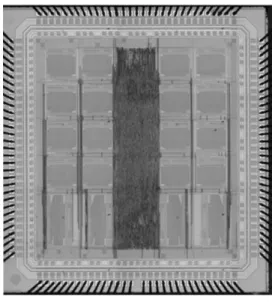
ME module constantly access the external memory of the video coding system, the system bus will become too busy. So we use on-chip SRAM to store current block data and search area data. The amount of the external memory access can be signifi-cantly reduced in this way, although the ME module needs some extra clock cycles to load the data. Data reuse of overlapped search area between horizontally adjacent macroblocks is also adopted to reduce the loading cycles. The required working fre-quency is 21.2016 MHz. The chip photo is shown in Fig. 10.
Fig. 10. Chip photo.
TABLE VI CHIPSPECIFICATIONS
We store search area data in 16 144 8-SRAM modules, as the RAM00–RAM15 organized in Fig. 9. Four 16 32-SRAM modules controlled by the same address generator are used to store current block data. According to testing results, the chip works well for all test patterns, and the maximum working fre-quency is 27.8 MHz, which is high enough to support MPEG-4 Simple Profile Level 3 (CIF 30 Hz). The other chip specifica-tions are shown in Table VI. Because of the fixed processing cycles, low requirement of bandwidth on system bus, low gate count, high processing capability, and high video quality, our design is a good silicon IP core and can be easily integrated in video coding systems.
V. CONCLUSION
We proposed GEA and its architecture design for fast block matching ME. Our algorithm can solve several problems en-countered by SEA. The main concept is to first roughly com-pare candidate blocks with current block, and then to precisely compare the best roughly matched candidate blocks with cur-rent block. Unlike other fast algorithms, GEA is hardware oriented. No initial guess or special scan order of search posi-tions is required, the data flow is regular, the processing cycles are fixed, and the motion-compensated results are almost the same as those obtained by the FSBMA. We also proposed a VLSI architecture for GEA. It mainly includes a systolic part, a parallel adder tree, and a parallel comparator tree. For typ-ical applications, the area–speed performance of our design is much better than many existing architectures based on the FSBMA.
ACKNOWLEDGMENT
The authors would like to thank Dr. T.-C. Wang and W.-M. Chao for discussion and many valuable suggestions.
REFERENCES
[1] Information Technology—Coding of Moving Pictures and Associated
Audio for Digital Storage Media at up to About 1.5 Mbit/s—Part II: Video, ISO/IEC 11 172-2, 1993.
[2] Information Technology—Generic Coding of Moving Pictures and
As-sociated Audio Information: Video, ISO/IEC 13 818-2 and ITU-T
Rec-ommendation H.262, 1996.
[3] Information Technology—Coding of Audio-Visual Objects—Part 2:
Vi-sual, ISO/IEC 14 496-2, 1999.
[4] Video Codec for Audiovisual Services at p2 64 Kbit/s, ITU-T Recom-mendation H.261, Mar. 1993.
[5] Video Coding for Low Bit Rate Communication, ITU-T Recommenda-tion H.263, Feb. 1998.
[6] Draft ITU-T Recommendation and Final Draft International Standard of
Joint Video Specification, ITU-T Recommendation H.264 and ISO/IEC
14 496-10 AVC, Joint Video Team, May 2003.
[7] T. Koga, K. Iinuma, A. Hirano, Y. Iijima, and T. Ishiguro, “Motion compensated interframe coding for video conferencing,” in Proc. Nat.
Telecommunications Conf., 1981, pp. C9.6.1–C9.6.5.
[8] R. Li, B. Zeng, and M. L. Liou, “A new three-step search algorithm for block motion estimation,” IEEE Trans. Circuits Syst. Video Technol., vol. 4, pp. 438–442, Aug. 1994.
[9] L. M. Po and W. C. Ma, “A novel four-step search algorithm for fast block motion estimation,” IEEE Trans. Circuits Syst. Video Technol., vol. 6, pp. 313–317, June 1996.
[10] M. J. Chen, L. G. Chen, and T. D. Chiueh, “One-dimensional full search motion estimation algorithm for video coding,” IEEE Trans. Circuits
Syst. Video Technol., vol. 4, pp. 504–509, June 1994.
[11] S. Zhu and K. K. Ma, “A new diamond search algorithm for fast block matching motion estimation,” IEEE Trans. Image Processing, vol. 9, pp. 287–290, Feb. 2000.
[12] J. Y. Tham, S. Ranganath, M. Ranganath, and A. A. Kassim, “A novel unrestricted center-biased diamond search algorithm for block motion estimation,” IEEE Trans. Circuits Syst. Video Technol., vol. 8, pp. 369–377, Aug. 1998.
[13] A. M. Tourapis, O. C. Au, M. L. Liou, G. Shen, and I. Ahmad, “Optimizing the MPEG-4 encoder—Advanced diamond zonal search,” in Proc. IEEE Int. Symp. Circuits and Systems (ISCAS’00), 2000, pp. 674–677.
[14] B. Liu and A. Zaccarin, “New fast algorithms for the estimation of block motion vectors,” IEEE Trans. Circuits Syst. Video Technol., vol. 3, pp. 148–157, Apr. 1993.
[15] M. J. Chen, L. G. Chen, T. D. Chiueh, and Y. P. Lee, “A new block matching criterion for motion estimation and its implementation,” IEEE
Trans. Circuits Syst. Video Technol., vol. 5, pp. 231–236, June 1995.
[16] M. J. Chen, “Predictive motion estimation algorithms for video com-pression,” J. St. John’s & St. Mary Inst. Technol., vol. 15, pp. 197–214, June 1997.
[17] Z. L. He, C. Y. Tsui, K. K. Chan, and M. L. Liou, “Low-power VLSI de-sign for motion estimation using adaptive pixel truncation,” IEEE Trans.
Circuits Syst. Video Technol., vol. 10, pp. 669–678, Aug. 2000.
[18] W. Li and E. Salari, “Successive elimination algorithm for motion esti-mation,” IEEE Trans. Image Processing, vol. 4, pp. 105–107, Jan. 1995. [19] X. Q. Gao, C. J. Duanmu, and C. R. Zou, “A multilevel successive elim-ination algorithm for block matching motion estimation,” IEEE Trans.
Image Processing, vol. 9, pp. 501–504, Mar. 2000.
[20] M. Brünig and W. Niehsen, “Fast full-search block matching,” IEEE
Trans. Circuits Syst. Video Technol., vol. 11, pp. 241–247, Feb. 2001.
[21] Digital Video Coding Group, ITU-T Recommendation H.263 Software
Implementation, Telenor R&D, 1995.
[22] Y. S. Chen, Y. P. Huang, and C. S. Fuh, “Fast block matching algorithm based on the winner-update strategy,” IEEE Trans. Image Processing, vol. 10, pp. 1212–1222, Aug. 2001.
[23] K. M. Yang, M. T. Sun, and L. Wu, “A family of VLSI designs for the motion compensation block matching algorithm,” IEEE Trans. Circuits
Syst., vol. 36, pp. 1317–1325, Oct. 1989.
[24] T. Komarek and P. Pirsch, “Array architectures for block matching algo-rithms,” IEEE Trans. Circuits Syst., vol. 36, pp. 1301–1308, Oct. 1989. [25] C. H. Hsieh and T. P. Lin, “VLSI architecture for block matching motion estimation algorithm,” IEEE Trans. Circuits Syst. Video Technol., vol. 2, pp. 169–175, June 1992.
[26] Y. S. Jehng, L. G. Chen, and T. D. Chiueh, “An efficient and simple VLSI tree architecture for motion estimation algorithms,” IEEE Trans.
Signal Processing, vol. 41, pp. 889–900, Feb. 1993.
[27] H. Yeo and Y. H. Hu, “A novel modular systolic array architecture for full-search block matching motion estimation,” IEEE Trans. Circuits
Syst. Video Technol., vol. 5, pp. 407–416, Oct. 1995.
[28] Y. K. Lai and L. G. Chen, “A data-interlacing architecture with two-dimensional data-reuse for full-search block matching algorithm,” IEEE
Trans. Circuits Syst. Video Technol., vol. 8, pp. 124–127, Apr. 1998.
[29] Y. H. Yeh and C. Y. Lee, “Cost-effective VLSI architectures and buffer size optimization for full-search block matching algorithms,” IEEE