A Video Coding Algorithm Based on Image Warping and
Nonrectangular DCT Coding
Yung-Ming Chou and Hsueh-Ming Hang
Dept. of Electronics Eng., National Chiao-Tung University
Hsinchu, Taiwan 30010, Republic of China
ABSTRACT
Object scalability is a new trend in video coding research. This paper presents an attempt of designing an object-oriented coding based on the notion of irregular mesh and image warping. Three techniques are employed: motion compensation based on image warping, image segmentation and object tracking based on (mesh) nodal point adjustment, and nonrectangular DCT coding performed on the irregular mesh. The preliminary simulationresults of the PSNR values and the subjective coded image quality indicate that this coding scheme is suitable for object scalable coding at low bit rates.
Keywords: object-oriented coding, image warping, nonrectangular DCT coding, low-bit-rate video coding
1. INTRODUCTION
Video compression technology plays an important role in transmitting video signal through channels with con-strained capacity, such as cable TV (CATV), direct broadcasting satellite (DBS), and computer networks. Motion-compensated transform coding is an effective and popular approach in removing the temporal and spatial redundancy in a video sequence and thus is adopted by the international video coding standards, ITU 11.261, 11.263, ISO MPEG-1, and MPEG-2. However, the block motion compensation approach cannot cope with non-translational motion, such as object rotation, object deformation, and camera zooming. In addition, for specific applications where object scalability is necessary, the simple extension of the block-based coding scheme is not very effective. The goal of this study is to develop an effective yet simple object scalable compression scheme. Our scheme is based on the irregular mesh posed on the video frames. Three techniques are employed: motion compensation based on image warping, image segmentation and object tracking based on (mesh) nodal point adjustment, and nonrectangular DCT coding performed on the irregular mesh.
Typically, an object-oriented coding scheme segments an image sequence into objects and then encodes objects separately. It uses not only motion estimation but also video segmentation that separates different moving objects. The main difficulty of object-oriented coding approach is the interdependency between motion estimation and video segmentation in a scene. That is, in order to have an accurate motion estimation, the object boundaries have to be first identified correctly; however, in order to have an unambiguous video segmentation it is necessary to estimate motion and object boundary information precisely for every pel. The above dilemma has been studied by many researchers and several solutions have been suggested,1 but they are often very complicated and not yet practical.
Recently, image warping technique has been used in motion estimation and compensation for video coding.27 In these studies, spatial transformation is the tool that finds the mapping parameters between the source image and the warped image. Some researchers combine this technique together with DCT coding and use it in image compression.5 Because the image block shape is not rectangular after warping, we can view this technique somewhere between the conventional block-based method and the exact object-based method (that has a precise description of object boundary). However, the aforementioned studies still use rectangular shape DCT coding. Thus, they do not take the advantage that the textures within the same object are often homogeneous. Also, they are often not object scalable coding schemes. In order to accomplish the above objectives, we suggest a video coding algorithm which uses the image warping technique for both motion compensation and image segmentation and employs a nonrectangular DCT coding scheme for the warped patches inside objects.
2. NODAL POINT TRACKING
2.1 Intraframe Nodal Points Adjustment
In the process of using image warping techniques for video coding, nodal points (vertexes of mesh or patch) should be properly selected. For the object scalability purpose, we wish these nodal points can carry both the motion information and the object boundary information. Therefore, in the first frame (intraframe), a simple edge
detection algorithm is used to help shifting the nodal point from an initially regular mesh point to an image edge point. Let N(X, Y) denote the location (coordinates) of the nodal point (X, Y) at frame t, where X and Y are the column and the row indices, respectively. At the beginning, the initial nodal points are uniformly distributed in the image plane; that is, N_1(X, Y) =(KX, KY),
0 < X < and 0 < Y < ,
whereK is the horizontal (and vertical)size of the initial mesh (patch). The total number of nodal points is (
+
1)( + 1) and is unchanged for the entire image sequence.The procedure of shifting an intra nodal point (X, Y) towards an edge point is as follows:
1 . Pickup a square area around the nodal point (X, Y), which is Axy {(x, y)KX —
1
< x < KX + ,
KY
—2. For each pel (x, y) ..4xy, use the four 3 x 3 Sobal operators shown in Fig. 1 to calculate the gradients
go, g45, g9o, and gialongthe four directions O, 450,900, and135°, respectively.
-1 0 1
Fl -i oJ
-1-1 -1
-1 0 1
-1 0 1
0 0 0]
-1 0 1
0 1
1 1 11]
(a) (b) (c) (d)
Figure 1 : Sobal operators used for detecting edges of different directions
3. For each pel in Axy , themaximum absolute gradient value among the four directional gradients is chosen to
be the significant gradient g3 of that pel. Then, calculate the mean and the variance of g3 inside Axy. 4. Calculate the threshold TH =E{g3}+ 2o,where i the the square root of Var{g3}.
5. If the threshold TH ]S less than 8, Axy i5 treated as a smooth region (no edge points exist) and the nodal point coordinate No(X, Y) is not shifted; that is,
N0(X,Y) =N..1(X,Y).
6. Otherwise, examine the significant gradient of each pel inside Ay . A pel is called an edge point if its significant gradient is greater than the threshold.
7. Calculate the Euclidean distance between the edge point and the initial mesh point. The new nodal point location N0(X, Y) is set to the edge point with the minimum Euclidean distance.
Notice that choosing the minimum distance can reduce the mesh variation. This would be helpful in reducing the entropy of sending side information.
In the above procedure, we can further force the minimum distance to be larger than zero. This property ensures that the edge points are not on the initial mesh nodes. Thus we can use the coordinates of nodal point to examine
shift associated with the nodal point (X, Y). If Do(X, Y) 0, then the nodal point (X, Y) is an edge point. Also, because ..4xydoesnot overlap with each other,
No(Xi,Yi) No(X2,Y2), if(Xi,Yi) (X2,Y2)
Namely,any two intraframe nodal points will not overlap after shifting.
2.2 Interframe Nodal Points Adjustment
In order to maintain the object boundary information, we trace the nodal points from one frame to another. The motion estimation technique is used for this purpose. The popular exhaustive search block matching algorithm is employed. Centering on the nodal point, a square area in the previous frame is selected as the "block" or "window" used in matching. We look for the best-matched candidate block in the search region in the current frame. Then, the new nodal point (in the current frame) is the displaced version of the old nodal point (in the previous frame). That is,
N(X,Y)
=N1(X,Y)+
D(X,Y),where D (X, Y) =
(d
,d)
is the displacement vector for the interframe nodal points. An example of nodal point tracking result is shown in Fig. 2.3. FOREGROUND/BACKGROUND SEPARATION
Motion picture segmentation techniques have been explored by many researchers recently.8'° Designing a general, robust, and accurate video segmentation scheme is a rather difficult problem. Usually, it requires both the intraframe information —objectboundaries, and the interframe information —object movement. We do not plan to develop
a general video segmentation algorithm in this study since our primary goal is to develop an object scalable coding scheme. Since we now only consider the videophone-type sequences, pictures are segmented into two areas: the object (foreground) and the background.9 We further assume the background of our test images are rather smooth. In other words, the background does not contain strong image edges. Under these assumptions, we design a simple intraframe segmentation algorithm. In our algorithm, only the edge nodal points identified by the edge detection scheme (Sec. 2.1) are used. Together with the nodal point tracking scheme (Sec. 2.2) we can trace object boundaries from one frame to another without transmitting additional information.
Each quadrilateral patch (mesh) consists of four vertexes (nodal points) with indices (X, Y), (X + 1, Y), (X + 1, Y + 1), and (X, Y + 1). A binary boundary map value Bo(X, Y) is assigned to this patch; it indicates whether the patch belongs to the object or not. That is,
— 1' 1 ,
if
this patch belongs to the object;B0 X, Y —
, otherwise. (1)
Notice that the initial (zeroth frame) patches are identical to the regular square blocks in the conventional video coding schemes. Our segmentation algorithm is composed of three steps: (1) patch classification, (2) boundary determination, and (3) triangular refinement.
3.1 Patch Classification
At the beginning, we partition the patches into two groups —edgeand non-edge —basedon the number of edge
nodal points associated with a patch, Vo(X, Y). If Vo(X, Y) 2, this patch belongs to the edge group; otherwise, it belongs to the non-edge group. This procedure produces an initial description of the object boundary. A segmented image of "Suzie" after patch classification is shown in Fig. 3(a).
3.2 Boundary Determination
Based on the patch classification results, we further determine the object boundary. We assume only one convex object presents in the picture; thus there are generally two boundary patches in each row (Y): the left-boundary
(b) Frame 0 after nodal points adjustment
(c) Frame 10 with updated nodal points
Figure 2: An example of nodal points tracking Figure 3: An example of intraframe segmentation
patch (Xi ,Y) and the right-boundary patch (Xr ,Y)of the object. The patches between these two boundary patches are assumed to be a part of the object. That is, if X1
X
<
Xr,then Bo(X, Y) = 1;otherwise, B0(X, Y) =0.(a) Initial regular mesh ( a)Frame Ualterpatch ciassincation
(b) Frame 0 after boundary determination
The procedure of finding the left-boundary patch for each row is as follows:
1. Find the first edge patch (X, Y) we encounter in the scanning direction from left to right.
2. Check V0(X, Y) (edge nodal points) of this patch. If V0(X, Y) > 2, then this patch (X, Y) is chosen to be the left-boundary patch.
3. If Vo(X, Y) =2,further check whether the coordinates of these two edge points. If they are not No(X + 1, Y)
and No(X + 1, Y + 1) (the right border of this patch), then this patch (X, Y) is the left-boundary patch; otherwise, the patch (X, Y) is excluded from the edge group. Then, the next patch (X + 1, Y)becomes the left-boundary patch. (The left border of this patch is the object boundary.)
A set of similar rules are used to acquire the right-boundary patches. A segmented image of "Suzie" after boundary determination is shown in Fig. 3(b).
3.3 Triangular Refinement
Examining Fig. 3(b), we often find artifacts on the object boundaries due to the sparse quadrilateral patch borders. These saw-tooth-like artifacts appear when the boundary patches contain two or more edge points in their vertexes. A more precise object boundary can be obtained by splitting the boundary patchesinto triangles and excluding the exterior triangle from the object if appropriate. The refinement procedure is as follows:
1 .
If
the diagonal vertexes are edge points, they are used to form the partition line that splits the boundary patchinto two triangles.
2. Furthermore, if an exterior vertex (not located on the partition line) is not an edge point, the triangleassociated with this non-edge vertex is excluded from the object and thus the partition line becomes a part of the object boundary.
The final segmented image of "Suzie" after triangular refinement is shown in Fig. 3(c). We now haverather natural boundary contours.
4. SPATIAL TRANSFORMATION
A spatial transformation is a mapping that establishes a spatial correspondence between the pels in an image and their warped counterpart. There are three popular spatial transformations: perspective transformation,bilinear transformation, and affine transformation. Because affine transformation is rather simple and matches our mesh structure for motion compensation and image segmentation, it is chosen to be the mapping model in our video coding scheme.
4.1 Triangle Partition
In calculating the affine transformation parameters, triangular patches instead of quadrilateral patches are our basic units. There are two ways to partition a quadrilateral patch into two triangular patches. Therefore, weneed a Iriangular map To(X, Y) that records the partition lines for the patches inside the object.
T X —
f
1, if (X + 1, Y) and (X, Y + 1) are the partition line vertexes; 2' — 1 0 ,
if
(X, Y) and (X + 1, Y + 1) are the partition line vertexes.We wish the partition line would coincide with the edge curves inside the object. Then, pels inside one triangle would likely have similar statistical characteristics. The following rules are used to determine the To(X, Y) values. They are developed based on the number of edge vertexes Vo(X, Y) of an object patch.
1 . Vo(X,Y) =0: This quadrilateral patch is often a smooth region. Therefore, any two diagonal vertexes can be
chosen to be the partition line. We simply use the sum of coordinates to determine To(X, Y). If X + Y is odd, To(X,Y) =1;otherwise, To(X,Y) =0.
2. V0(X, Y) =1: If there is only one edge nodal point on the quadrilateral patch, it should not be a part of the
partition line. That is, the diagonal pair that does not contain this edge point becomes the partition line. 3. Vo(X, Y) =2: If these two edge nodal points form a diagonal pair, they form the partition line. Otherwise,
we further examine the coordinate shifts of these two edge vertexes. The one with larger coordinateshift (sum of the horizontal and the vertical shifts) forms the partition line. This type of patches usually do not contain image edges crossing the diagonals. Hence, the partition line selection is not critical.
4. Vo(X, Y) =3: The only non-edge vertex should not be a part of the partition line.
5. Vo(X, Y) =4: If the four vertexes of this quadrilateral patch are all edge points, we compare the sum of the coordinate shifts of two diagonal pairs. The one with larger value is chosen to be the partition line.
The segmented images with triangle partition for "Suzie" and "Claire" sequences are shown in Fig. 4.
Figure 4: Images with triangle partition: (left) Suzie and (right) Claire
4.2 Mapping Parameter Calculation
In affine transformation, the coordinates of the corresponding pels in two successive frames are related by the following two equations:
U =
allx+al2y+a13, (3)V =
a2lx+ a22y + a23, (4)where (u, v) and (x, y) represent the pels in the previous and the current frames, respectively. Since the degrees of freedom of an affine transformation are six, we can solve the unknown mapping parameters by using the coordinates of three given points in these two frames. Assume that N(Xo, Yo) =(SO,yo), N(X1 ,Y1)
=
(x1,yi), and N,(X2 ,Y2)=
( X2,Y2) are three nodal points that constitute a triangular patch in the current frame; and (Xo,Y0)
=
(UO,vO), N_1(X1 ,Y1)=
(UO,vcj), andN_1(Xo, Yo) =(ttO,vo) are the corresponding nodal points in the previous frame. Inthe matrix form, we thus have
tLO Ui U2
all a12 a13
XO X1 X2V0 Vi V2
a21 a22 a23
Yo Yi Y2
. (5)Or we abbreviate (5) as U =AX. If X is invertible, the mapping parameters can be obtained by A =
UX
. LetA(X, Y) be a 4 x 3 matrix representing the mapping parameters of the quadrilateral patch (X, Y) between frame t and frame t —1. It, in fact, contains two groups of affine transformation parameters, each for a triangular patch.
4.3 Warping Based Motion Compensation
Based on the affine transformation model (4), an estimate of a pel in the current frame can be derived from a pel in the previous frame:
f(x,y) =
ft_i(u,v)
, (6)where fj(x, y) and Jj(x, y) are the original and the predicted pels in the current frame t, respectively. That is, the temporal redundancy between two nearby frames is reduced by using the image warping technique. Its function is similar to that of motion compensation. Because the mapping parameters are no longer integers, (u, v) can be non-integers. Because only integer-coordinate pels are available, the non-integer coordinate pels are generated by using the bilinear interpolation. Let (u—, v—), (u—, v+), (u+, v—) and (u+, v+) be the four nearest neighbors of (u,v); then
f(ZL,v)
=
(1-
cE)(1 - 3)f(u-,v-) + (1 -
a)9f(u-,
v+) + c(1 -/3)f(u+,v-) + cj3f(u+, v+),where a is the distance between u and u—, and /3 is the distance between v and v— .Thepreceding equation is valid for the special cases that u— =zt+
=
u,or v— =v+=
v.5. CODING STRUCTURE
The intraframe coding and interframe coding procedures are different in our system. They are separately described below.
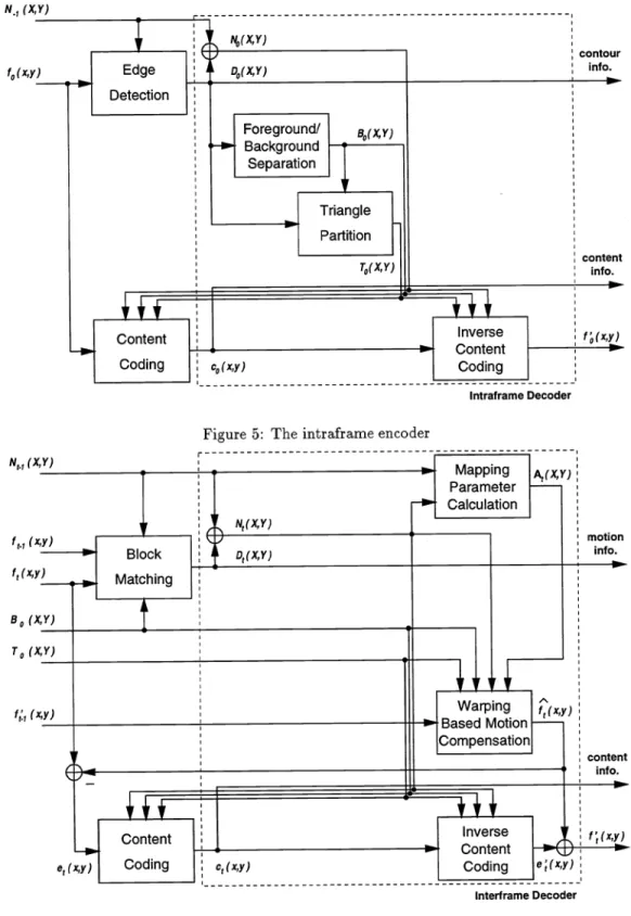
5.1 Intraframe Coding
Figure 5 shows the block diagram of the proposed intraframe coding scheme. Essentially, two types of information are processed: the nodal points and the image intensities. As described in the previous two sections, in the nodal point processing, the edge detection algorithm is first used to shift the initially evenly-distributed nodes to their nearest edge points if such edge points exist. The shift values D0(X, Y) can be used to separate intraframe patches into two groups —the object and the background. The object boundary map B0(X, Y) is thus produced. For the patches belonging to the object, a triangular map To(X, Y) is produced by using the triangle partition procedure. It is necessary to send the side information D0(X, Y) to the decoder because the same maps are needed in the decoding
process.
In the image intensity processing, the pel value fo(x ,y) is coded by a content coding algorithm to be described
later. Notice that the inverse content coding is also included in the encoder to provide the coded intensity f(x, y) that will be used for encoding the next frame. It is thus clear that the decoding process is a part of the encoder shown in Fig. 5.
5.2 Interframe Coding
Figure 6 shows the block diagram of the proposed interframe coding scheme. As described in the previous two sections, the block matching algorithm is used to provide the displacement information of the nodal points. In order to trace the shift of the nodal points frame by frame, the displacement vector D(X, Y), t >0for the nodal point (X, Y) is transmitted to the decoder. Based on the nodal point coordinates in the previous and current frame we can derive the mapping parameters A(X, Y) for each patch. The predicted pel value f(x, y) is produced by the affine transformation and bilinear interpolation. The nearly uncorrelated error signal
e(x, y) =
f(x,
y) —f(x,
y)is the input to the content coding unit. Similar to the intraframe content coding, the interframe decoding process is included in the interframe encoder.
N1 (X,Y)
Figure 6: The interframe encoder Content
Coding
Intraframe Decoder
Figure 5: The intraframe encoder
Mapping Parameter Calculation
e1(x
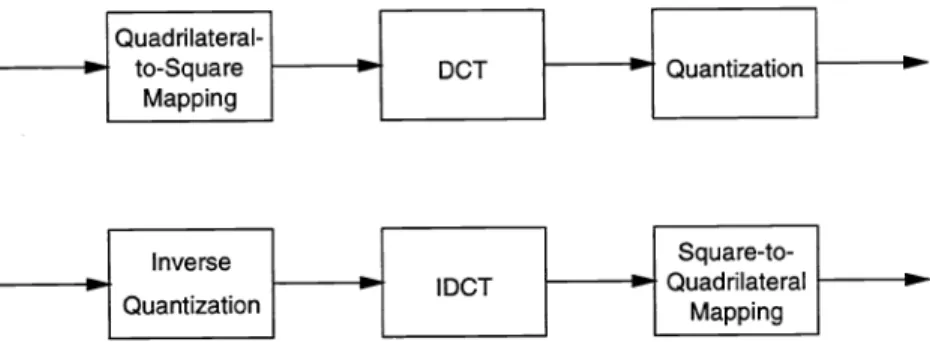
Content Coding ] Interirame Decoder5.3 Content Coding
DCT coding is the most frequently-used content coding algorithm in the conventional video coding schemes. The ordinary DCT operates on the rectangular patches (blocks). This restriction does not fit into our image warping based coding system. Therefore, we propose a nonrectangular DCT coding algorithm to solve this problem. A quadrilateral-to-square mapping is first performed on the irregular patches to generate square blocks. Then the traditional DCT coding operation is applied to the square blocks. This mapping step is similar to the spatial transformation described in Sec. 4.2. The nonrectangular DCT decoding at the decoder performs a square-to-quadrilateral mapping after the conventional DCT decoding. The quantization strategy we use here is the same as the MPEG1 video coding standard. The content coding algorithms for the encoder and the decoder are shown in Fig. 7. Notice that because of the bilinear interpolation used to generate the non-integer coordinate pels in the forward and backward warping processes, these two mappings are not invertible. That is, even without quantization,
the reconstructed pels after going through the forward and the backward warping processes are not identical to the original pels. A more sophisticated interpolation operation may help reducing this error.
Quadrilateral- I I 1 to-Square
1 DCT
1 Quantization I Mapping I I I Inverse I ISquare-to-1
. .1 IDCT
1 Quadrilateral I Quantization I I MappingFigure7: The content coding scheme: nonrectangular DCT
6.
SIMULATION
RESULTS
This section will show some preliminary simulation results of the proposed video coding scheme. We choose the initial square mesh (patch) size (between two nearby nodal points) K= 8. In the content coding we use squares of size 8 x 8 in performing the quadrilateral-to-square mapping. Thus, the total number of transform coefficients of the nonrectangular DCT coding is the same as the pel number of an image. In the block matching procedure for shifting interframe nodal points, the data window (block) size is 7x7 (since K =8)and the search range is set to The
exhaustive search algorithm with haif-pel accuracy is used to increase the estimation accuracy which is important for nodal point tracking. Two video sequences have been tested; they are "Suzie" and "Claire" . Both are in the C1F240 format; that is, the picture size is 352 pels by 240 lines and 30 frames per second.
A frequently used coding performance measurement is the peak signal-to-noise ration (PSNR)
2552 PSNR=lOlog10
E{e2}' (7)
where coding error e is the difference between the original image and the coded image. Notice that we calculate the error in the object portion only. The PSNR values of different quantization scale Q for "Suzie" and "Claire" are shown in Fig. 8. As discussed at the end of Sec. 5, even we do not quantize the transform coefficients, the pel distortion exists due to the interpolation used in the nonrectangular DCT coding. Using a larger quantization scale results in lower PSNR values, i.e., larger coding errors. We also calculate the entropy of the quantized coefficients. They are shown in Fig. 9. Except for the first intraframe, the entropy per frame is around 1K bits for Q= 16. This is a rather small number. However, the overhead of nodal point shift information is probably around 2K to 4K bits per frame for C1F240 pictures.
Although PSNR is a popular measure of image objective quality, it is not always matches the subjective image quality. To subjectively evaluate the image quality, portions of the coded images with Q =16 for "Suzie" and
E
34
\-
- -. - S•—-S S
cr35 5-z .--
.- S z Q=4 (1)33 — \ 5555_ J) o_ —---Q=4 34 32 -33 31 32 30 . . . . . . . . . 31 Q=16 Q=16 20 3G , 0 5 10 15 20 25 30 0 5 10 15 20 25 30Framenumber Frame number
Figure8: PSNR at various quantization scales: (left) Suzie and (right) Claire
"Claire" are shown in Figs. 10 and 11, respectively. Although a rather large quantization scale is used, the coded images for both sequences can still maintain a good subjective quality without noticeable blocking artifacts. Due to quantization and bilinear interpolation, the coded images are somewhat blurred. Notice that after 20 frames, the object is still well tracked by shifting the nodal points only. Generally speaking, the proposed video coding scheme is very suitable for low bit-rate coding and object scalable coding.
7. CONCLUSIONS
Object scalability is a new trend in video coding research such as the MPEG-4 activity. Our proposed video coding algorithm is developed based on the image warping technique which can track object boundaries as well as reduce interframe correlation. A simple edge detection scheme shifts the initial square mesh to match the object edges. A simple foreground/background separation algorithm demonstrates the intraframe segmentation for the first frame. Then the ordinary block matching algorithm is used to trace the movement of the patch nodal points. The only information we need to transmit to regenerate the object contour at the decoder is the nodal point movement. However, the warped patches are generally nonrectangular. We thus propose a nonrectangular DCT coding scheme to solve this problem. Simulation results indicate that both the objective PSNR performance and the subjective image quality are promising.
Several modifications are under development that may further improve the coding performance. Motion segmen-tation should be included to update the boundary map and the triangular map. Patches should be split and merged when they become too large or too small. The forward and backward mapping errors in the nonrectangular DCT coding may be reduced using a more sophisticated interpolation algorithm. Also, since the warped patches may have more homogeneous contents, some shape adaptive coding techniques"'3 may be adopted to increase coding
efficiency.
8. REFERENCES
{1] H. G. Musmann, M. Höetter, and J. Ostermann, "Object-oriented analysis-synthesis coding of moving images,"
Signal Processing: Image Commun., vol. 1, pp. 117—138, Oct. 1989.
[2] G. J. Sullivan and R. L. Baker, "Motion compensation for video compression using control grid interpolation," Proc. ICASSP'91, pp. 2713—2716, Toronto, Canada, May 1991.
1 O 6 '6 51O
.
Ez
z Iu 102 0 5 10 15 20 25 30 0 5 10 15 20 25 30Frame number Frame number
Figure9: DCT coefficient entropies at various quantization scales: (left) Suzie and (right) Claire
{3] V. Seferdis and M. Ghanbari, "General approach to block-matching motion estimation," Opiical Engineering, vol.32, pp. 1464—1474, July 1993.
[4] J. Nieweglowski, T. G. Campbell, and P. Haavisto, "A novel video coding scheme based on temporal prediction
using digital image warping," IEEE Trans. Consumer Elecfron., vol. 39, pp. 141—150, Aug. 1993.
[5] C.-L. Huang and C.-Y. Hsu, "A new motion compensation method for image sequence coding using hierarchical
grid interpolation," IEEE Trans. Circuits Sys. Video Technol., vol. 4, pp. 42—52, Feb. 1994.
[6] Y. Nakaya and H. Harashima, "Motion compensation based on spatial transformations," IEEE Trans. Circuits
Sys. Video. Technol., vol. 4, pp. 339—356, June 1994.
[7] Y. Wang and 0. Lee, "Active mesh—A feature seeking and tracking image sequence representation scheme,"
IEEE Trans. Image Process., vol. 3, pp. 610—624, Sept. 1994.
[8] M. Höetter and It. Thoma, "Image segmentation based on object oriented mapping parameter estimation,"
Signal Processing, vol. 15, pp. 315—334, March 1988.
[9] C. Lettera and L. Masera, "Foreground/background segmentation in videotelephony," Signal Processing: Image
Commun., vol. 1, pp. 181—189, Jan. 1989.
[10] N. Diehl, "Object-oriented motion estimation and segmentation in image sequences," Signal Processing: Image Commun., vol. 3, pp. 23—56, Jan. 1991.
[11] M. Gilge, T. Engelhardt, and It. Mehlan, "Coding of arbitrarily shaped image segments based on a generalized orthogonal transform," Signal Processing: Image Commun., vol. 1, pp. 153—180, Jan. 1989.
[12] H. H. Chen, M. R. Civanlar, and B. G. Haskell, "A block transformcoder for arbitrarily shaped image sequences,"
in Proc. ICIP'9l, vol. I, pp. 85—89, Austin, Texas, Nov. 1994.
[13] I. Donescu, 0. Avaro, and C. Roux, "A shape-adaptive transform for object-based coding," in Proc. ICIP '96, vol. III, pp. 347—350, Lausanne, Switzerland, Sept. 1996.
Q=4
4r
'¼
r
L
I,
(a)The 0th coded frame
/
/
c
/r
(c)The 20th coded frame
Figure 10: Portions of the coded "Suzie"
2.::.
.: •1•
a
(c) The 20th coded frame Figure 1 1 : Portions of the coded "Claire"
(a) The 0th coded frame