IEEE TRANSACTIONS ON CIRCUITS AND SYSTEMS FOR VIDEO TECHNOLOGY, VOL. 8, NO. 2, APRIL 1998 143
On the Design of Selective Coefficient DCT Module
Chung-Yen Lu and Kuei-Ann Wen
Abstract— In this transactions letter, an innovative selective coefficient discrete cosine transform (SCDCT) architecture is pro-posed which is designed for selective coefficient computation and straightforward row–column computation. Having these features, the selective coefficient DCT core will fit for various area/speed requirements. It can save the transposition delay to simplify the computation flow of two-dimensional (2-D) DCT and, in view of circuit implementation, SCDCT is multiply-free and thus area/speed efficient.
Index Terms—DCT, selective coefficient, 2-D DCT.
I. INTRODUCTION
T
HE discrete cosine transform (DCT) defined by Ahmedet al. [1] in 1974 has recently found a number of
applications in the area of digital image processing [2]–[4]. Fast algorithms for the DCT are, therefore, of significant practical interest. For the fast computation of two-dimensional (2-D) DCT, there are two categories: row-column method form one-dimensional (1-D) DCT [5]–[9] and direct 2-D DCT [10]–[12]. However, for fully pipelined implementation of the row–column method, a complicated matrix transposition architecture as well as two 1-D DCT modules are required. On the other hand, large area and bandwidth are also required for the implementation of direct 2-D DCT.
We proposed a 1-D DCT module, called selective coeffi-cient DCT (SCDCT), which is multiply-free, and it provides different bandwidth requirements with a buffer engine, in addition, it can avoid heterogeneous problems in video/image compression.
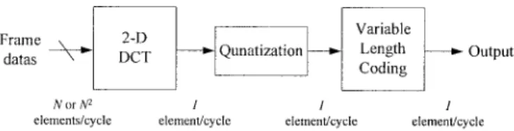
As illustrated in Fig. 1, the data flow for the transmitted video is inherently in the form of sequential data. No matter row–column method or direct 2-D DCT will generate 8 or 64 elements/cycle, which are far more than the bandwidth of quantization process.
To overcome this, we specified the design features to be: 1) sequential output; 2) straight forward row–column computation; and 3) selective coefficient computation. These three features avoid the transposed memory delay and straight match the throughput of the whole system. Being a building block of 2-D DCT, the SCDCT module provides the flexibility of the assembling and thus supply for the various area/speed tradeoffs.
Manuscript received March 21, 1995; revised January 18, 1996. This paper was recommended by Associate Editor K.-H. Tzou.
The authors are with the Institute and Department of Electronics Engineer-ing, National Chiao Tung University, Hsinchu 30010, Taiwan, R.O.C.
Publisher Item Identifier S 1051-8215(98)00111-6.
Fig. 1. Typical DCT coding system.
II. SELECTIVE COEFFICIENT DCT MODULE The 1-D DCT of a real data sequence
is defined by
for (1)
where and , . We take 8 8
as the standard size of a processing block. For the matrix form of (1), we defined constant matrix and data matrix ( ) as
(2) where , , , for and (3) where where where where .
The matrix form of 1-D eight-point DCT will be expressed as
(4) for where is selection matrix
(5)
144 IEEE TRANSACTIONS ON CIRCUITS AND SYSTEMS FOR VIDEO TECHNOLOGY, VOL. 8, NO. 2, APRIL 1998
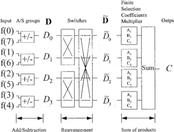
Fig. 2. Block diagram of selective coefficient DCT module.
and permutation matrices , as illustrated in the following:
From (4), the 1-D DCT computation could be decomposed into three steps.
1) Compute the data vector .
2) Rearrange , , , and by mapping .
3) Sum up the products by . The corresponding cosine factor set is chosen from by selection matrix . Since the cosine factors are constant, the product could be im-plemented by shifting and adding operations. Therefore, we could obtain a multiplier-free DCT module. The block diagram of SCDCT module is illustrated in Fig. 2. The input of the SCDCT module is a 1-D frame with eight elements, as denoted . The output is one of the 1-D DCT coefficients, .
III. MULTIPLY-FREEIMPLEMENTATION OF SCDCT The main functions of SCDCT are: 1) addition/subtraction operation; 2) arrangement process; and 3) sum of product of data vector with cosine factor set.
TABLE I
BOOTH’SREPRESENTATION OFCOSINE FACTORS
TABLE II
COMPARISONS OFCIRCUITCOMPLEXITY INREAL-TIME
HARDWAREIMPLEMENTATION OFEIGHT-POINTDCT
The idea of multiply-free implementation of SCDCT is to take advantage of the fact that cosine factors are fixed so that multiplication of the factors are then shifted and added to produce output.
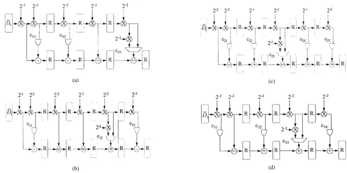
We define four sets of finite selection coefficients multipliers (FSCM’s) for the right-most block as shown in Fig. 2
The booth’s representation of the cosine factors are listed in Table I.
Therefore, the cosine factors control the addition or subtrac-tion of the shifting data. Namely, if the th bit of cosine factor is 1, then data are added, if it is , subtraction of the data will be processed, otherwise ignoring it. The block diagrams of the four FSCM’s are shown in Fig. 3. The fully pipelined architectures of FSCM’s consist of shifters, adders, and some simple logic gates.
The hardware implementation of FSCM is based on shifting and adding structure. Therefore, the circuit complexity is much less than many fast DCT algorithms. Table II compares the circuit complexity of SCDCT with fast 1-D DCT algorithms. The input bandwidth of SCDCT is determined with a buffer engine as illustrated in the Appendix.
IV. CONCLUSION
The SCDCT module is based on the property of arbitrary selective coefficient computation. It has three attributes: 1) sequential input/output could smooth the data flow and reduce the memory bandwidth requirement; 2) zero transpose memory
IEEE TRANSACTIONS ON CIRCUITS AND SYSTEMS FOR VIDEO TECHNOLOGY, VOL. 8, NO. 2, APRIL 1998 145
(a)
(b)
(c)
(d) Fig. 3. The structures of FSCM’s: (a) FSCM-1, (b) FSCM-2, (c) FSCM-3, and (d) FSCM-4.
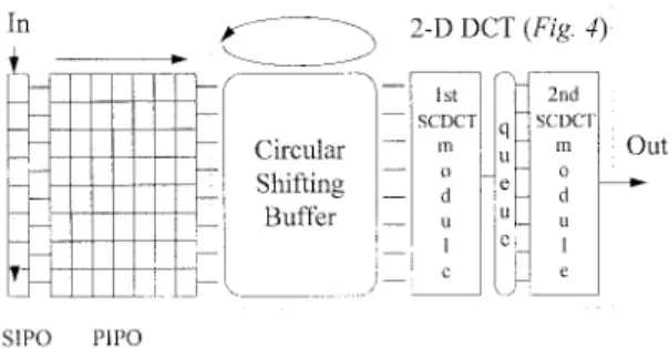
Fig. 4. Implementation of 2-D DCT by two SCDCT modules.
delay could straight forward the row-column computation flow; and 3) the flexibility of area/throughput tradeoff. In the architecture of the SCDCT module, with FSCM being proposed, the multiplier-free structure makes it area effi-cient.
APPENDIX
APPLICATIONS OF SCDCT
The SCDCT module is able to compute an arbitrary 1-D DCT coefficient. This property allows the SCDCT mod-ule to be adopted for various requirements, such as
delay-free for 2-D DCT by row–column method, DCT truncation coding, adaptable area–time tradeoff and bandwidth require-ment.
A. Implementation of Delay-Free Transposition 2-D DCT
The row data vectors ,
, are sequentially fed into the first SCDCT to get intermediate 1-D DCT coefficients. The column vectors of
the intermediate DCT coefficients ,
, are sequentially fed into the second SCDCT to get 2-D DCT coefficients. The whole block diagram of
146 IEEE TRANSACTIONS ON CIRCUITS AND SYSTEMS FOR VIDEO TECHNOLOGY, VOL. 8, NO. 2, APRIL 1998
Fig. 5. The reduction of the bandwidth requirement.
Fig. 6. The output bandwidth of 2-D DCT is two elements/cycle.
the 2-D DCT is illustrated in Fig. 4, the straight computation of column 1-D DCT coefficients save the large transposition buffer and transposition delay.
B. Reduction of Bandwidth Requirement with Buffer Engine
Many fast 2-D DCT’s need eight elements per cycle for input/output. To match that, excessive I/O should be used. Using SCDCT combined with SIPO/PIPO as shown in Fig. 5, it is clear that the data flow is single-in single-out even for the 2-D DCT.
C. Modulization for Area–Time Tradeoff
Higher throughput of a 2-D DCT could be achieved with more SCDCT modules. Due to the property of free selective coefficient computation, different numbers of SCDCT modules can be used for various bandwidth requirements of 2-D DCT. Therefore, the different tradeoff between area and throughput can be easily fulfilled. As illustrated in Fig. 6, four SCDCT modules can double the output throughput.
Fig. 7. Specific DCT application: Partial DCT.
D. DCT Truncation Coding
For DCT truncation coding, which forces the high frequency DCT coefficients to be zero, only a lower frequency DCT subblock is required. With SCDCT, a special DCT architecture could be designed to calculate any 4 4 subblock of the 2-D DCT as illustrated in Fig. 7.
REFERENCES
[1] N. Ahmed, T. Natarajan, and K. R. Rao, “Discrete cosine transform,”
IEEE Trans. Comput., vol. C-23, pp. 90–93, Jan. 1974.
[2] D. Le Gall, “MPEG: A video compression standard for multimedia applications,” Commun. ACM, vol. 34, no. 4, pp. 46–58, Apr. 1991. [3] M. Liou, “Overview of the p 2 64 kbits/s video coding standard,”
Commun. ACM, vol. 34, no. 4, pp. 59–63, Apr. 1991.
[4] W. B. Pennebaker and J. L. Mitchell, JPEG—Still Image Data
Com-pression Standard. New York: Van Nostrand Reinhold, 1993. [5] W. H. Chen, C. H. Smith, and S. C. Fralick, “A fast computational
algorithm for discrete cosine transform,” IEEE Trans. Commun., vol. COM-25, pp. 1004–1009, Nov. 1977.
[6] M. D. Wagh and H. Ganesh, “A new algorithm for the discrete cosine transform of arbitrary number of points,” IEEE Trans. Comput., vol. C-29, pp. 269–277, Apr. 1980.
[7] B. G. Lee, “A new algorithm to compute the discrete cosine transform,”
IEEE Trans. Acoust., Speech, Signal Processing, vol. ASSP-35, pp.
1243–1245, Dec. 1984.
[8] H. Malvar, “Fast computation of discrete cosine transform through fast Hartley transform,” Electron. Lett., vol. 22, no. 7, pp. 352–353, Mar. 1986.
[9] Y. Chan and W. Siu, “A cyclic correlated structure for the realization of discrete cosine transform,” IEEE Trans. Circuits Syst.–II, vol. 39, pp. 109–113, Feb. 1992.
[10] M. Vetterli, “Fast 2-D discrete cosine transform,” in Proc. ICASSP’85, Mar. 1985, pp. 1538–1541.
[11] N. I. Cho and S. U. Lee, “DCT algorithms for VLSI parallel implemen-tation,” IEEE Trans. Acoust., Speech, Signal Processing, vol. 38, pp. 121–127, Jan. 1990.
[12] , “A fast 42 4 DCT algorithm for the recursive 2-D DCT,” IEEE