EfFects
of
an impurity
on
the
conductance
and
thermopovver
of
a
saddle-point-potential
quantum
point
contact
C.
S.
ChuInstitute ofPhysics, National Chiao Tung University, Hsinchu 80050, Taiwan, Republic of China and Department ofElectrophysics, National Chiao Tung University, Hsinchu 80050, Taiwan, Republic Of China
Ming-Hui Chou
Department ofElectrophysics, National Chiao Tung University, Hsinchu $0050, Taiwan, Republic Of China (Received 18May 1994;revised manuscript received 11July 1994)
The conductance Gand the thermopower
S
of asaddle-point-potential quantum point contact inthe presence of ab-potential impurity are calculated. For the case when an attractive impurity is located inside the quantum point contact, there are dips, peaks, and kinks in G. These structures can be found below and near the band bottom ofsome transverse subbands, respectively. The peaks in Ggive rise to double peaks inS
and the dips in Ggive rise toashift inthe peak positions ofS,
towards a smaller chemical potential value. In addition, a broad dip in G is found to giverise to negative thermopower in regions between the peaks of
S.
For the case when an attractive impurity is located in the classical forbidden region for the electrons, we 6nd in G the structures that correspond to resonance tunneling and resonance reaection. The correspondingS
is found toshow large and negative spikes. Our study shows that structures not so transparent in Gmanifest unequivocally in
S,
renderingS
avery informative physical quantity to be measured.I.
INTRODUCTION
The quantum transport in quantum point contacts
(QPC)
has receiveda
lotof
attention, both theoreticaliand experimental, in recent years. These systems are
electrostatically defined narrow constrictions connecting two high-mobility two-dimensional electron gas. The
width W of
a QPC
is small(W
—
Ap) enough to ex-hibit quantization efFects, and the corresponding lengthL is short enough
(L
«
l, the mean free path) tomake possible the study
of
quantum ballistic transport. In the absenceof
defects and impurities, it is found experimentally ' that the conductance G is quantized,in units of 2e /h. However, this quantization in G is vulnerable
to
the presenceof
even one impurity inthe constriction, according
to
recent theoretical and experimental ' 2 studies. More specifically, theoreticalstudies show that the conductance G can exhibit dip
structures
just
below the thresholdof
a transverse sub-band both in the caseof a
weak attractive short-rangescatterer present in the constriction and in the case
of
attractive long-range scatterers separated from the QPC
by
a
spacer layer. These dip structures in Gare observed in recent experiments. ' Thus dip structures in G canbe used
to
distinguish an attractive scatterer from a re-pulsive scatterer but cannot be usedto
tell an in-planescatterer from an off-plane scatterer.
Besides the conductance
G,
thermopowerS
is another physical property of QPC systems in which quantization efFectmanifests unequivocally.It
was first showntheoret-ically by Streda that in
a
narrow constriction the ther-mopowerS
exhibits peak structures. His calculation in-volved an ideal narrow constrictionof
which thelongitu-dinal transmission coefficient through the constriction is
a
step functionof
energy, and he concluded that the peak values of8
are quantized, given by (ks/e) ln2/(i+
1/2).
These peaks occur when the Fermi energy p equals the
threshold of the
(i
+
l)th
transverse subband, startingfrom
i
=
1.
Later theoretical studies ' show similaros-cillations in
S
except that these peak values are modified when the longitudinal transmission coefficient throughthe constriction is no longer
a
step functionof
energy, which correspondsto
the case when the widthof
thecon-striction is changing, either adiabatically or ina
saddle-point-potential
QPC.
is The aforementioned quantum os-cillations are demonstrated in recent experiments.These peak features render
S
potentially very sensitive to the configurationof
theQPC
systems, especially when p is in the vicinityof
a
transverse subband threshold.%e
expect that both G and
S
can be usedto
explore the configuration ofQPC
systems and that they play com-plementary roles in such regard. Hence we consider, in this paper, the effect ofimpurity on8
in QPC systems.Our purposes in this work are
to
study andto
comparethe efFect
of
impurity on the thermopowerS
and thecon-ductance G in
QPC
systems. The QPC is modeled bya
saddle-point potential which is simple and quite realistic,giving no sharp corners and containing the essential fea-tures ofthe electrostatically induced QPC bottleneck. The impurity is taken
to
be short range which, in thecase of
a
saddle-point potentialQPC,
is appropriately described bya
b potential. The efFectof
the impuritylocation on G and
S
is studied by considering the im-purityto
be located in the central cross section of theQPC.
Similar study has been carried out by Levinson et al. for Gusinga
confinement-potential Green'sEl'l'I:CTS OFAN IMPURITY ON THE CONDUCTANCE
AND.
.
.
14213tion method. In this work, we propose
to
apply another method,a
mode-matching method, to theQPC
systems.This method can be easily extended
to
other situations such as applying an external magnetic fieldto
the QPCsystems. In addition, new insights are obtained when our analysis includes both the cases for an impurity present inside and outside the
QPC.
An impurity is outside theQPC
when it is located in the classical forbidden region for the electrons.For an attractive impurity located inside the QPC, our results show dips and peaks in Gwhich occur below and near the threshold
of
some transverse subbands, respec-tively. Sometimes, when p isat
the thresholdof
a
trans-verse subband, the peaks are so small that they appear
more like kinks in
G.
In addition, there isa
resonance tunneling peak in G in the pinchoK region. The kinks inG
give riseto
double peaks inS
and the dips in G give riseto
a shift in the peak positionsof
S,
towardsa
smaller chemical potential value. A broad dip in G is foundto
give negative thermopower, in regions betweenthe peaks
of
S.
The resonance tunneling in the pinchofI' region results inS
a
large peak followed by a large neg-ative dip. Our study showsthat,
near the thresholdof
asubband,
S
exhibitsa
relatively large double peak struc-ture even inthe case when Ghas onlya
small kink. This corroborates our intuition thatS
issensitiveto
the QPC con6guration near the thresholdof
a
transverse subband.For
a
not-too-weak attractive impurity located outaidethe
QPC,
our results show both additional peak and dip which correspondsto
resonance tunneling and resonance refiection occurring outside theQPC.
In sucha
regime,the thermopower
S
of
theQPC
deviates far &om thatof
its impurity-free counterparts, exhibitinga
large neg-ative dip followed bya
large positive spike. On the otherhand,
if
the impurity outside the constriction is stronglyattractive, the above resonant features
of
S
disappear. InSec.
II
we developa
mode-matching method for the electron scattering in the saddle-point potentialQPC.
The thermopower is, within the Landauer multichannel
approach, ' ' related
to
the current transmission coef-6cients. InSec.
III
we present some numerical examplesto
illustrate thatS
is very sensitiveto
the con6guration of theQPC
in the threshold region of a transversesub-band. Finally,
Sec. IV
presentsa
conclusion.transmission coefficient. There is transmission coefficient
~t„„~
(Ref. 21)wheret„„
isthe coefficient appearing inthe scattered wave function and is associated with the nth transmitted
state.
There is alsoa
currenttrans-mission coefficient
T
which is the ratio between the transmitted current in the nth channel and the incident current in the nth channel. These two transmissionco-efBcients are difFerent when n is difI'erent &om
n'.
So far, this difl'erence has not been emphasized enough and many papers use the term trunsmission coeQcient when they actually are referringto
current transmissioncoef-6cient.
In the following, the total transmitted current is ex-pressed in terms
of
the current transmission coefficientT„„.
is'2o We take the left (right) reservoirto
have chem-ical potential p(p
—
b,y,) and temperatureT
+
b,T (T).
The total transmitted current, from the left
to
the right reservoir, is given byJ
=
—
—
dE
[n~(E,
p,
T
+
b,T)
h
n(E,
IJ,——
b,p,T)]
)
T„„.
,n,n'
where
n~(E,
p,T)
is the Fermi-Dirac distributionfunc-tion and
—
e isthe charge ofan electron. In choosing the lower limitof
the energy integration, we have assumedthat
p
—
E
&&k~T,
whereE
is the lowest electronenergy in the reservoir.
Within the linear response regime, the conductance G isobtained &om
Eq. (1)
by takingAT
=
0, and we have202 2 oo
dE
~-
I)
h g
dE)
where Ap
=
—
eLV.
Similarly, within the linear response regime, the ther-mopower
S
is obtained &omEq.
(1)
by takingJ
=
0,such that20 d
E—
dE
—
dE
i)
T„„
)
kgT
)
T
dE)
II.
IMPURITY
SCATTERING
INSADDLE-POINT POTENTIAL
In this section, we consider
a
saddle-point potentialQPC
which connects two particle and energy reservoirs.The quant»m transport phenomena are related
to
thequantum mechanical scattering inthe
QPC.
is' 0Incidentelectron in the nth transverse subband
of
the left reser-voir isscattered intheQPC
and gives rise to transmittedcurrents in allthe propagating channels inthe right
reser-voir. Westress that in the case
of
multichannel quantumscattering, we should be more speci6c when referring
to
The current transmission coefficients
T „t
depend ontheconfiguration of the
QPC.
In the following, we considera
saddle-point potential V,z(2:,y),
given byV.p(x,y)
=
U—
Ux
+ U„y,
(4)V'-&(*
y)=
V-~(*)
~(y—
y-).
where the electrostatic potential
at
the saddle U istakento
be zero. An impurity located in the central crosssec-tion
of
the saddle-point potential, with the impurity po-tential V; ~given byassin that the numerical results
ob-tained using
a
b potential V; p(z y) as iii q aieessentially
t
esame as usi'
l
f
V as long as the potential range is s or etentia or zmp,
than all other relevant length scales. n suc
ca
constant V in
Eq. (5)
is given byfunction
V
=
V; pxydxdy.
E'
=
/i2k2/2m and theChoosing the energy unit
E
'
—
1&~ where kg isa
typical Fermi wave length unita
=
(~,
w~ ~ ~
v ' the two-dimensional Schrodinger
vector
of
the reservoir, e wo- ' equation becomes[-V
—
(uz
+(u„y
+u
b(z)8(y
—
y )4'(z,
y)=E~(z
y)(6)
re (u
=
/2mU
//iks2, ,~„=
/2mU„/hk~~, and eHere,
~
=
mCischaracterized V//i~. The con6guration of the
/PC
is2m ('
.
esu
ue,
andy.
Inb the dimensionless parameters
u,
~~, particular, the ratio (u„/u~)=
IW,The unperturbed transverse motion is quantize in o ~2n
+
1~&u and normalized wavesubbands, with energy ~ n
where
H
is the Hermite polynomial and n starts kom zero.'on
z
along the/PC
The unperturbed wave functionx
or ' h th subband satisfies the equation for an electron in
t
e n sua
+
(dz
+
6~ %jan~(z)=
0, Bx4
= E
—(2n+
l)~
is the energy for the motionwhere
e„=
—
nalong
z
u'ireet
ion.n. The dependence of„z
there are two
g„(z)'s,
implied. For every value
of
e„,
there are wo given by22(a}
3.0 ~p=00
~p=-0.
1 ~p--0.
3 ~p=-0.
4 Vp--0.
7 ee eeeeoc ~P'0 % /I l W / 2.0—
AlI
CV0
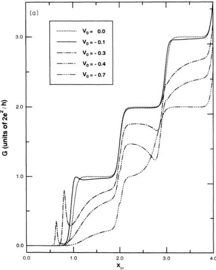
lA O~ CFIG.
1.
(a) Conductance G ofof theth PCv
=
0.0 case cor-as afunction ofx„.
T
evo=
responds to an ideal Q
PC.
Four otherim-=
—
0.1—
0.3,—
0.4, and purity strengths: v=
—
. ,—
.
,—
.
, d—
0.7 are s own.h . The impurity is located at the center ofthe+PC.
(b) ThermopowerS
ofthe/PC
as afunction ofz„
for the samex
=2.
shows detail8
structures nearx„=
0.0
0.0 2.0
50 ErveCTS OFAN IMPURITY ON THECONDUCTANCE
AND.
. .
14215(
—
imxl
@„(x)=
xg(u
exp ~xMi
—
+i
",
—,
mux
(4
4~
2)
(10)
Here,
Q,
(@ ) is an even (odd) functionof
z
andM(a,
b,z)is Kummer's function.Using
g„,
andQ„,
we constructa
stateQ„;„(z)
[tp„,
„f
(x)
jwhich has only positive (negative) currentden-sity in the asymptotic region
(x
~
—
oo).
Similarly, we constructa
stateg„„t
which has only positive current density in the asymptotic regionz
~
+oo.
The results arewhere
4-,
'-(*)
=
4-(*)
+
~-
@-(*)
@-,
-~(*) =
0-o(*) +&-@
.
(&)4e.,ref(+)
=
4rao(+)+
7'
Wne(+)&i
—
i
(
ere„l
..
f xe„'t
cosh
—
ssznh4~
&4~.
)
&4~.
& 2(i
&4+
'4~. )
and 'Yn=
Pn=
—
o'~.With an impurity located
at
(z,
y)=
(0,
y),
the scat-tering wave functionof
an nth subband electron withtotal
energyE
and incident from the left-hand side can bewritten in the formy)y„;
(&)+)
&„y
(y)@
„f(x),
&&0,
~.
'(*
y)=
&)
t„,
„y„,
(y)y„,
.
„,
(*),
*&0.
atching the wave function
4+
at
x
=
0 and integrating the Schrodinger equation acrossx
=
0 leadsto
two matrixequations
0
Ol ~~
C lO-
& (b) ll s.o ~!',!i
ii
!i
2.0 I IlI/I
/I
l 1.0 0.2 0.0 II'
j I 2.0 V,= OO Vo=-O.i Vo=-03
V,=-0.
4 Vo=-0.
7FIG.
1.(Continued). 0.0 1.0 2.0 X 3.0where
cx+
pK = PT,
1+R=
JT,
(n)
„=
n„h
(P)
=P
~.
,(&)-
=
~-~-,
(R)
„=
r
(T)
- =&-,
2v~(&)-
=
~-
—
4 (u-)4-(u-)P-.
(14)
(»)
forward to show from
Eq. (17)
that, in the case of no impurity (v=
0), t
=
b [1+
exp (—
me /w )j which is the well-known result fora
perfect saddle-pointpotential.
'
The incident current
J;„,
is given by8
J
nine=
hm &o(~n one+
4no) (~nOne+
/no)K~—OO Ox
and the transmitted current
J„
t,
„
in the nth channel is given byFrom
Eq. (14)
andEq. (15),
we obtain the transmission coefficientst
„,
which isthe matrix elementof
T
and is given by&=(&
—
»)
'(~
—
~)
The matrix
T
is symmetric because both(P
—
p
J)
and(n
—
p)
are symmetric. In deriving the abovema-trix
equations, we have used the relationsQ„,
(0)
=
1,g„',
(0)=
g„(0)
=
0, and @„' (0)=
+id,
where theprime means derivative with respect
to
z.
It
isstraight-g„,
„.
„=
hmC.
it„„~'
(P.
y.
.
+
0.
.
)X~OO
x
—
(P-
0-
~+
&-
-)
'
Here,
C
is adimensionless constant.The current transmission coefficient
T„„
is given by(19)
Jn',tran
Jn,inc (20)
Finally, substituting
Eqs. (18)
and(19)
intoEq. (20),
and taking the required asymptotic limit, we have3.
0—
Vo= 0.00 Vo=-0.10 V,=-0.
30 Vo=-0.50 Vo=-0.
55 2.0—
(p)I
CV0
th C1.
0—
~e$J
/jll'
/j
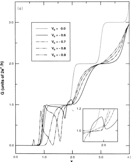
FIG.2. (a) Conductance i of the
+PC
as a function of
x„.
The impurity is at the edge of the+PC
whenz„=
2.1.
The dotted curve corresponds to the ideal+PC
results and four other impurity strengths are shown. (b)Thermopower8
ofthe+PC
asafunction ofz„.
TheconBguration isthe same asin(a).
0.0
0.0 1.0 2.0
X
50 EFFECTS OFAN IMPURITY ONTHECONDUCTANCE
AND.
.
.
14217T„„=
(t „~ exp (n—
n')
2r!"
(4
4u X 2 t,4+'4~.
)
2 4)~(2'
)
(21)
In the case when there is no impurity,
it
is obvious thatt„„
is diagonal and thatT
„=
~t
„~
.
III.
NUMERICAL
EXAMPLES
In this section, we present in three different situations
the G and
S
of a
/PC
asa
functionof
the chemicalpotential p
of
the reservoir. The effective widthof
the/PC
is increased as y,increases. In the first situation, anattractive impurity is fixed in its location, closer
to
thesymmetry axis, such that the impurity is always inaide
the
/PC.
In the second situation, an attractive impurityis, again, fixed in its position but is
at
a
greater distance from the symmetry axis such that it is outside the/PC
in the lower p, regime and is inside the system in the
higher
p
regime. The effect of the impurity strength is also examined in the above two situations. Finally, inthe third situation, the strength
of
the impurity is fixed while its transverse location is changing.We take the
/PC
to
be that ina
high-mobility GaAs-Al Gaq As with typical electron density n2.
5x
10~~cm,
m'
=
0.
067m„and
A»=
500 A. Thus our choiceof
length scalea'
=
k& ——79.
6A, and energy scaleE'
=
5~k&s/2m'=
9meV=
104K.
In all the fol-lowing numerical examples, we have chosenk~T
=
0.
01
(T
1K),
u=
0.
125,andw„= 0.5.
Withsuchchoice ofparameters, the/PC's
effective lengthto
width ratioI/W
=
4.
In the following numerical examples, the im-purity potentials v were, in fact, rescaled and becamevo cue
In Figs.
1(a)
and1(b),
we plot the variation of G andS,
respectively, ofa
/PC
asa
function of thechemi-cal potential p,
.
For convenient purposes, the abscissa isgiven by
z„
z„=
-!
—
+1
/, 1(p,
&~s
)
(22)which truncated integer value is the number of propa-gating channels below p,
.
The effective half-widthof
the/PC
is given by yg(2z„—
1)/u& forz„)
0.5.
Anattractive impurity is located
at
(z,
y )=
(0,0).
Our results include casesof
five impurity strengths: v0.
3
I02
(b)
II 0.1 II! I[0
Qc
lO 0.0—
'~
-0.1 -0.2—
I I I !I Iz/
"
Vo= O.0O Vo=-0.
10 Vo=030
V,=-o.
so V,=-o.
ss
FIG.
2. (Continued). -0.3
1.
01.
5 2.0 2.5 3.0 3.50.
0,—
0.
1,
—
0.
3,
—
0.
4, and—
0.
7.
Except in the pinchoK region(x„(
1),
the impurity remains inside theQPC.
There is, in the pinchoK region, no propagating chan-nel in the QPC so that transmission occurs only through tunneling which gives rise
to
a
peak in G, as is shown inFig.
1(a).
For a more attractive impurity, this peak in G occursat a
lowerx„and
witha
lower peak height.These features are consistent with the interpretation
of
sucha
peak in termsof
resonant tunneling transmission.In the case
of a
more attractive impurity, the resonantpeak in G occurs
at
a
lowerx„because
p, hasto
lineup with
a
lower quasiboundstate.
On the other hand, in the saddle-point potential configuration, the effective tunneling distance is increased, rendering the peak height in Gto
be lowered. For an even more attractive impu-rity, such as v &—
0.
7inFig. 1(a),
there is no resonantpeak because the impurity quasibound state is too deep
to
allow resonant tunnelingto
occur. For the case ofthermopower, in this pinchoK region, the resonant tun-neling gives rise
to
a pairof
positive peak and negative dip structures, with the peak locating on the lowerx„
side. We Gnd that this peak-dip structure can beunder-stood qualitatively by noting firstly in
Eq. (3)
thatS
is zero whenP„„,
T„„
isa
constant nearp
and, secondly,that if
P„„,
T„„were
todepend linearly on energy nearp, ,
S
would be proportionalto
the slope ofP„,
T
„.
Inthe low temperature regime, as we consider here, we have
,
T„„G,
and the peak-dip structure inS
isfoundto
reflect qualitatively the slope of the peak inG.
%ith
this insight, we point out in particular that for the cases
v
= —
0.
3, and—
0.
4, the former case has a larger peak in G but asmaller peak-dip magnitude. This is relatedto
the fact that the former peak hasa
slower rate ofrise and drop. This result demonstrates clearly the G prof-ilesensitive feature
of
S
in the low temperature regime.In the region when there are propagating channels, there are dip structures in G
just
belowx„=
3 for thecases v
= —
0.
3 and—
0.
4.
Followinga
dip structure.on the larger
x„side,
G rises more rapidly and has a greater slope than the case for an idealQPC.
Thus, ap-plying our Gprofile-sensiti-ve analysis forS,
the effect of the dip structure in G isto
give riseto
alarger peak as well as a shift in the peak location ofS
towardsa
lowerx„value.
This feature is demonstrated inFig.
1(b) nearx„=
3.
Furthermore,a
broad dip, such as the case forv
=
—
0.
4,gives rise tonegativeS
in the region whenx„
is between 2 and3.
Besides dip structure in G, there is akink in G
at
x„=
2. Similar structures have been found by Levinson et a/. These kinks in Gare not found in nar-row constrictions ofwhich the con6nement potentials are3.0 i 4 t t 2.
0—
I
hl0
Nr
FIG. 3. (a) G vs
z„.
The location ofthe impurity is the same as in 2(a). The figureshows that a more attractive impurity gives
rise to resonant reBection and transmission
when it is still outside
(z„(
2.1) the QPC.(b)
S
vsx„.
Same configuration asin(a).
0.0
0.0 1.0 2.0
X
50 EFFECTS OFAN IMPURITY ON THECONDUCTANCE
AND.
.
.
14219 independentof
the longitudinal coordinates. The kink inG is shown, in
Fig. 1(b), to
give rise toa
double-peakstructure in
S.
This can be explained with our Gpr-ofilesensitive analysis. We point out that for v
=
—
0.
7, thekink in G isbarely recognizable while the corresponding double peak in
S
is quite spectacular, with the higherpeak height almost double that of the ideal
QPC.
Figures2(a), 2(b), 3(a),
and3(b)
show the G andS,
respectively, for the case when the impurity islocatedat
y=
2.5.
The impurity strength varies &om v=
0.
0to
v=
—
0.9.
As the chemical potential p, increases,the effective width ofthe QPC is increasing and the im-purity location changes &om eR'ectively outside
to
insidethe
QPC.
Inparticular, the impurity is at the edge oftheQPC
whenx„=
(u„y
+
1)/2.
We takeu„=
0.
5 so that the criticalz„
isabout2.
1.
One main purpose ofplottingFigs.
2(a)
and2(b)
isto
showthat,
fora
not-so-attractiveimpurity (v
(
—
0.
55),
the impurity effect only becomes evident whenit
is electively inside theQPC.
Figures3(a)
and3(b)
show, however, thata
more attractive im-purity has its effect felt even when it is still electivelyoutside the
QPC.
From
Fig. 2(a),
we see that for v=
—
0.
1 and v—
0.
3, a
signi6cant eKectof
the impurity comes in when x&)
2.
1.
This is reasonable because the impuritysects
the transport when it is efFectively inside theQPC.
The latter impurity givesa
dip anda
small peak in Gnearx„=
3.
The dip-and-peak structure in G(x„3
andv
=
—
0.
3)gives rise inS
to a
positive peak in between two negative dips, as shown inFig. 2(b).
As shown inFigs. 2(a) and
2(b),
the G plateaus as well as the dipstructures in region x~
)
2 are destroyed when the im-purity becomes more attractive. Thus the rising in Gfor x&
—
3 becomes less abrupt. The corresponding fea-ture inS
isa
gradual shift in the peak ofS,
away &omthe ideal QPC peak
at
x„=
3 and towardsa
smallerz„value.
Following the shiftingof
peak positions inS,
these peaks are broadened and their peak height lowered.
In addition, there is
a
peak in G, nearx„=
2, which isassociated with resonance tunneling occurring near the
edge of the
QPC.
This peak becomes more pronounced fora
more attractive impurity and the correspondingS
exhibitsa
peak followed bya
large negative spike. For the casev=
—
0.
5, the magnitudeof
the negativeS
spike is even greater than the magnitude of the ideal peak inS.
This isa signatureof
a
pronounced peak inG.
2.0
a
Ol O~c
M r 1.0 'I 1.5—
I' 'I r:I
I I I a ii II IIos
—
'
III
~
'1, I I ! III
-o-'slti
l ! -1.0 I t i emaamwm4$w~ 0.0v,
=oo
V =-Or6 V =-0.7vo--o.
8 V =- or9 2.0FIG.
3. (Continued). -1.5 1.0 1.5 2.0 X 2.5 I 3.0 3.53.0
V=00
X=Q5
= 1.0 I t I I~ = 1.5X=2Q
2.0—
O Ol0
thc
~tj~Ii@oooooeresr so+ t~'I
~ ~ 0
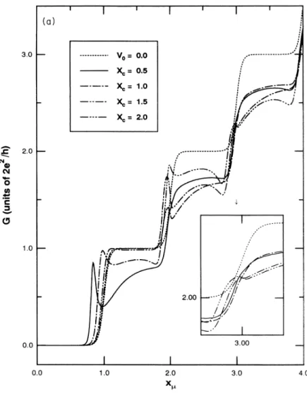
FIG.
4. (a) Gvsz„.
The impurity poten-tial vo=
—
0.3, the ideal QPC curve is givenby the dotted curve. Four impurity positions are shovrn. The impurity is at the edge of the
/PC
whenx,
=
z„.
(b)S
vsz„.
Same configuration as in(a).
1,0—
0.0 0.0 I 1.0 2.0 X 3.00 3.0 4.0As the impurity becomes even more attractive, as shown in Figs.
3(a)
and3(b),
new G andS
structuresare developed inthe region
x„&
2,which correspondsto
resonant reflection and resonant transmission when theimpurity is quite outside the
QPC.
Corresponding tothe resonant reflection dip inG,there isa
large negative spike following bya
large positive peak structure inS.
Note, in particular, that the magnitudesof
both the spike andthe peak can be up
to
fiveto
six times thatof
the idealS
peakat
x„=
1.
This demonstrates thatS
is very sensitiveto
resonant processes in the QPC systems.Finally, in
Figs. 4(a)
and4(b),
we plot G andS
for
a
v=
—
0.
3 impurity in various positions:x
0.
5,1.
0,1.
5, and2.
0.
The impurity is at the edge of theQPC
whenx„=
x,
.
From the results in previous figures, we see that this impurity is a weak attractive scatterer. In the pinchofF region, thex
=
0.
5 and1.
0 impurities give riseto a
resonant tunneling peak inG.
Thex
=
2.
0 impurity gives riseto
a
peak inGdueto
resonant tunnel-ing outside theQPC.
However, it is interesting to notethat the
x
=
1.
0,1.
5 impurities contributeto
peaks in Gnear
x„=
2 where the impurities are already inside theQPC.
Our results show that the impurity withx,
=
2.0 gives riseto
alarger G peakat
x„=
2 while it gives riseonly
to a
kink in Gat
integerx„=
3.
The correspondingstructure in
S
for this peak consists ofa
negative dip, as shown inFig.
4(b) .IV.
CONCLUSION
A mode-matching technique has been applied
to
studythe eKectofan impurity onthe conductance and the ther-mopower of
a
saddle-point-potentialQPC.
Our analysis demonstrates the correlation between the conductanceand the thermopower in the low temperature regime.
The correlation is established qualitatively using
a
G-profile serisitive analys-is. We show that
S
is very sensi-tiveto
the impurity near the thresholdof
a
transverse subband. In fact, our results show thatS
is closelyre-lated
to
the slopeof
G.
At integralx„values,
kinks in Gwhich are not so transparent can give rise
to
large dou-ble peaks inS.
Large negative spikes inS
arise dueto
the presence
of
sharper peaks and dips inG.
ThusS
E1'1ACTS OFAN IMPURITY ON THECONDUCTANCE
AND.
. .
14221 1.6 1.2 (b) 0.2 0.0vo=
OOXc=
05
Xc= 1'0 X =1.
5 X = 2.0 0.8I
-0.2 2,0FIG.
4. (Continued). 0.0—
-0.4—
1.0 2,0 X 3,0 re6ection dip inG.
Besides, we have studied the cases when the impurity is outside and inside the
/PC
and have demonstrated theresonant tunneling and the resonant re8ection occurring outside the
/PC.
Our results show in detail the effect onS
and G whena
short-range impurity is around the edge of the/PC.
Finally, this study shows that both Gand
8
can be usedto
explore the con6guration of/PC
systems and that they play complementary roles in such
regard.
ACKNOWLEDGMENTS
This work was partially supported by the National
Sci-ence Council
of
the Republic ofChina through Contract No. NSC82-0208-M-009-062.C.
W.J.
Beenakker and H. van Houten, in Solid State Physics, edited by H. Ehrenreich and D. Turnbull (Aca-demic, New York, 1991),Vol. 44, p.1.
B.
J.
van Wees, H.van Houten, C. W.J.
Beenakker,J.
G. Williamson,L.
P.Kouvrenhoven, D.van der Marel, andC.
T.
Foxon, Phys. Rev. Lett. 80,848(1988).D.A. Wharam,
T.
J.
Thornton,R.
Newbury, M. Pepper, H.Ahmed,J.
E.
F.
Frost, D. G.Hasko, D.C.
Peacock, D.A. Ritchie, and G.A.C.Jones,
J.
Phys. C21,
L209(1988). D.van Marel andE.
G.Haanapel, Phys. Rev.B
39,
7811(1989).
C.
S.
Chu andR. S.
Sorbello, Phys. Rev.B 40,
5941(1989).
P.Bagwell, Phys. Rev.
B 41,
10354(1990).
E.
Tekman andS.
Ciraci, Phys. Rev.B 4$,
7145(1991).
J.
A.Nixon,J.
H.Davies, and H.U. Baranger, Phys. Rev.B
4$, 12638(1991).
Y.
B.
Levinson, M.I.
Lubin, andE.
V.Sukhorukov, Phys. Rev.B 45, 11936
(1992).Y.
MLxegaki and D.K.
Ferry, Phys. Rev.B
4B, 15218(1992).
J.
Faist, P. Gueret, and H. Rothuizen, Phys. Rev.B
42, 3217(1990).
C. C.
Eugster,J.
A.del Alamo, M.R.
Melloch, and M.J.
Rooks, Phys. Rev.B
4B, 10 146(1992).P.Streda,
J.
Phys. Condens. Matter1,
1025 (1989). C.R.
Proetto, Phys. Rev.B
44, 9096(1991).
Y.Okuyama and N.Tokuda, Phys. Rev.
B
46,2610(1992). L. W. Molenkamp, H. van Houten, C. W.J.
Beenakker,R.
Eppenga, and C.T.
Foxon, Phys. Rev. Lett.65,
1052(1990).
L. W.Molenkamp, Th. Gravier, H. van Houten, O.
J.
A. Buijk, M. A. A. Mabesoone, and C.T.
Foxon, Phys. Rev.Lett.
88,
3765(1992).M. Biittiker, Phys. Rev.
B
41,
7906(1990).M. Buttiker,
Y.
Imry,R.
Landauer, and S.Pinhas, Phys.Rev.
B
31,
6207 (1985).U. Sivan and
Y.
Imry, Phys. Rev.B 33,
551 (1986).This de6nition oftransmission coefBcient can be found ina standard quantum mechanics textbook such asL.
l.
SchiK, Quantum Mechanics (McGraw-Hill, New York, 1971),p.103.
H. A. Fertig and
B.
I.
Halperin, Phys. Rev.8
36,
7969(1987).
M. Abramowitz and