10 Gbit/s tunable dual-wavelength
nonreturn-to-zero–to–return-to-zero data-format
transformer based on a non-direct-current-biased
Fabry–Perot laser diode
Yung-Cheng Chang and Gong-Ru Lin
We demonstrate the conversion of a nonreturn-to-zero (NRZ)-formatted electrical data stream into a wavelength-tunable return-to-zero (RZ)-formatted optical pulse code by externally seeding a synchro-nously sinusoidal-modulated Fabry–Perot laser diode (FPLD) with optical pseudorandom binary-sequence data at 10 Gbits兾s (Gbps). The FPLD without a dc-biased current was modulated by use of a power-amplified sinusoidal wave signal共⬃25.6 dBm兲 as an NRZ-to-RZ data-format transformer, which is regeneratively amplified by a closed-loop erbium-doped fiber amplifier. The gain switching and on– off keying operation of the FPLD is initiated under the seeding of self-feedback and external-injection signals. A maximum wavelength tuning range of 30 nm with a side-mode suppression ratio of greater than 36 dB is obtained. The power penalty of the NRZ-to-RZ data-format conversion at 10 Gbps is 1.5 dB. © 2005 Optical Society of America
OCIS codes: 070.4560, 060.1810, 190.2620, 070.4340.
1. Introduction
Versatile all-optical-controlled signal-processing techniques, such as clock frequency division by pe-riod doubling,1– 4 wavelength conversion by
all-optical modulation,5upstream traffic transmission
by injection locking,6 and non-return-to-zero
(NRZ)–to–return-to-zero (RZ) data-format transfor-mation,7have been demonstrated with Fabry–Perot
laser diodes (FPLDs). Owing to the considerations of electronic bandwidth and timing tolerance, the data-format converters8are potentially required for
use in interconnections in optical communication networks that employ different data formats. NRZ-to-RZ9 and RZ-to-NRZ10 data-format
transforma-tions have been demonstrated with nonlinear optical loop mirrors.11Later, all-optical data-format
conversions by use of a semiconductor optical
am-plifier12and gain competition13emerged. Moreover,
a wavelength-converted and logically inverted NRZ or RZ format has also been demonstrated.7 This
paper applies gain competition and feedback injec-tion techniques to demonstrate the generainjec-tion of a 10 Gbits兾s (Gbps) NRZ-to-RZ data-format-transformed data pulse train from a non-dc-biased FPLD. One can generate this data-format conver-sion by gain switching the non-dc-biased and purely sinusoidal-wave-modulated FPLD with external op-tical pseudorandom binary-sequence (PRBS) seed-ing. The proposed FPLD-based data-format converter can implement versatile functions, in-cluding transformation of an electrical NRZ signal into an optical RZ signal, generation of a wavelength-converted and tunable RZ signal, and dual-wavelength and PRBS-encoded gain switching and on– off keying.
2. Operating Principle
In the case here, the dc-bias current of the FPLD is set to 0 mA, and the peak amplitude of the rf sinu-soidal wave signal is set to just below the threshold condition in single-mode injection locking and gain switching of the FPLD. One can reduce the effective threshold current by increasing the intensity of ex-ternal injection, increasing the stimulated
recombi-The authors are with the Department of Photonics and Institute of Electro-Optical Engineering, National Chiao Tung University, 1001, Ta Hsueh Road, Hsinchu, Taiwan 30050. The e-mail address of G. R. Lin is grlin@faculty.nctu.edu.tw.
Received 21 April 2004; revised manuscript received 21 Decem-ber 2004; accepted 12 January 2005.
0003-6935/05/153058-05$15.00/0 © 2005 Optical Society of America
nation coefficient, and causing FPLD gain switching. The proposed FPLD NRZ-to-RZ data converter for performing dual-wavelength operation and wave-length conversion (Fig. 1) is based on dual-wavelength injection locking. Owing to the redshift of the gain profile under injection, the self-feedback seeding wavelengthfis adjusted slightly larger than
the maximal transmission intensity of the mode spec-trum of the FPLD, as shown in Figs. 1(a) and 1(b). When the FPLD is externally injection locked with another wavelength e, both f and e can be lased
simultaneously, achieving dual-wavelength opera-tion [Fig. 1(c)]. For achieving wavelength conversion,
the wavelength deviation betweene and the
wave-length at the local maximal transmission intensity must be higher than that between fand the
wave-length at the local maximal transmission intensity. Wavelength e is exactly coincident with one of the
FPLD’s longitudinal modes within the locking range, greatly reducing the threshold current for lasing at e. This situation also helps to eliminate the original
fbecause the gain profile of the FPLD redshifts
fur-ther. Eventually, thefoutput can be fully modulated
in a manner that complements the PRBS-encoded signal ate.
3. Experiment
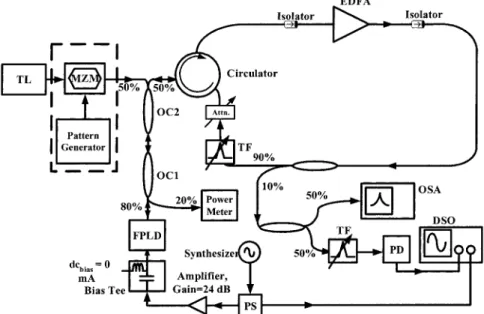
Figure 2 shows the configuration of the FPLD-based NRZ-to-RZ data-format transformer, which is based on a hybrid injection-locked FPLD– erbium-doped fi-ber amplifier (EDFA) link. A commercial 1.55᎑m FPLD operated at 27.5 °C with a threshold current, a mode linewidth, a central wavelength, and a mode spacing of 13 mA, 2.1 GHz, 1553.380 nm, and 1.14 nm, respectively, is employed. The FPLD was sinusoidally modulated from 1 GHz共1.012034 GHz兲 to 10 GHz with a 25.6᎑dBm sinusoidal signal. How-ever, the dc-biased current of the FPLD was set to 0 mA. In this case the FPLD was neither lasing nor gain switching because the overall driving current was below the threshold. The optical output of the FPLD was fed through an 80% fiber coupler (OC1) connected to another 50 –50 fiber coupler (OC2). One coupling branch of OC2 was fed through a circulator into a closed-loop EDFA, which forms an external cavity to achieve regeneratively amplified self-feedback. In the external seeding branch, the tunable laser that was externally modulated with an electri-cal PRBS data stream via a Mach–Zehnder intensity
Fig. 1. Dual-wavelength and wavelength-converted operating mechanisms of the FPLD (a) just below threshold, (b) in single-mode injection, (c) in dual-wavelength injection, and (d) under wavelength-conversion conditions. Dashed curve, injection-locking profile of the FPLD mode; solid bars, wavelengths in-jected ateandf.
Fig. 2. FPLD-based data-format transformer. Attn., optical attenuator; DSO, digital sampling oscilloscope; EDFA, erbium-doped fiber amplifier; OC1 and OC2, optical couplers; OSA, optical spectrum analyzer; PD, high-speed photodetector; PS, electrical power splitter; TF, tunable filter; TL, tunable laser; MZM, Mach–Zehnder intensity modulator.
modulator (MZM) was used as the external-injection seeding source for the FPLD by use of another cou-pling branch of OC2. In the self-feedback seeding branch, the amplified spontaneous emission from a commercial EDFA with a gain of 21 dB was filtered with an intracavity tunable narrow bandpass filter (TF), which then feeds back into the FPLD. An optical attenuator was used to control the amount of feed-back from the EDFA, which optimizes the spectral and temporal characteristics of the FPLD. Two opti-cal isolators inside the closed-loop EDFA were used to ensure unidirectional operation. The EDFA not only offers the amplified spontaneous emission to initiate the pulsation of the FPLD but also helps to amplify the mutually injection-locked pulse and the exter-nally injection-locked pulse from the FPLD. Prior to the feedback seeding, a polarization controller was applied to improve the side-mode suppression ratio (SMSR) and ensure that the feedback polarization was coincident with the preferred TE lasing mode of the FPLD. The seeding powers used for self-feedback and external injection were approximately 540W in the experiment conducted here.
4. Results and Discussion
When the wavelength is properly set, the filtered am-plified spontaneous emission signal of the EDFA in the self-feedback branch and the externally injected single-mode tunable laser signal concurrently help start the dual-wavelength gain switching in the purely sinusoidal-modulated FPLD (with a 0᎑mA dc-biased current). Gain switching can start only at the modulation peak of the FPLD because the optical feedback is relatively weak. Nevertheless, the ampli-fied self-feedback seeding or external injection dras-tically decreased the effective threshold current, facilitating the suppression of spontaneous noise of the gain-switched FPLD. The FPLD cannot be gain switched when the injection wavelength is beyond the locking range (approximately 0.2 nm). With ei-ther injection, the maximum difference between the wavelengths of the dual lasing modes can be tuned to as much as 30 nm; an optimized SMSR of larger than 36 dB remains constant within a tuning range of ⬃14.82 nm (13 FPLD modes). A broader FPLD gain spectrum will increase the tuning range of the wave-length. Notably, the minimum tuning range is deter-mined by the longitudinal mode spacing of the FPLD. Changing the frequency of repetition and the dc-bias conditions on the FPLD can also optimize the SMSR of the output signal.
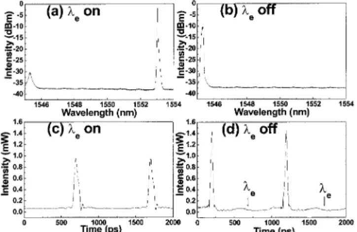
Figure 3 reveals the corresponding pulse shapes and spectra of the FPLD in the dual-wavelength scheme. Wheneis switched off [Fig. 3(b)], the peak
power offincreases 6.33 dB, as compared with that
in Fig. 3(a). In Fig. 3(c), under dual-wavelength operation, the pulse widths f and e are 35.7 and
44.7 ps, respectively. Aftere is switched off, an
in-crease of the pulse peak power between the upper traces of Figs. 3(c) and 3(d) is the same as that observed between Figs. 3(a) and 3(b). Obtained from the self-feedback branch are a pulse width
shorter and a peak power larger (by a factor of 1.2) than those obtained from the external-injection-seeding branch, owing to the regenerative amplifi-cation in the self-feedback loop and the shifted gain profile of the FPLD; Bouchoule et al. observed a similar result.14 Furthermore, when the output
power of the rf signal increased from 25.6 to 26.1 dBm, the SMSR decreased from 36 to 32 dB because the intensity of the other side modes of the FPLD are enhanced. However, such an SMSR still exceeds the values of all similar configurations re-ported elsewhere.15 The wavelength-conversion
mechanism is initiated as the wavelength of the self-feedback signal is detuned toward a shorter wavelength of the locking range. Figure 4 shows the pulse shapes and spectra of gain-switched FPLD pulses obtained with the wavelength-conversion scheme. As theesignal is switched on [Fig. 4(a)], the
gain atfis almost depleted, and the gain-switched
pulses atfare switched off, as shown in Fig. 4(c).
Fig. 3. Lasing spectra (upper figures) and pulse trains (lower figures) of the FPLD-based data-format transformer with the dual-wavelength scheme. (a) and (c)eis switched on. (b) and (d)eis
switched off.
Fig. 4. Lasing spectra (upper figures) and pulse trains (lower figures) of the FPLD-based data-format transformer with the wavelength-conversion scheme. (a) and (b) The optical spectra; (c) and (d) the corresponding pulse trains wheneis on and off,
However, when e is switched off [Fig. 4(b)], the
system returns to single-mode 共f兲 operation, and
the gain-switched pulses at f are switched on, as
shown in Fig. 4(d). The respective pulse widths are 42.4 ps [Fig. 4(c)] and 31.2 ps [Fig. 4(d)]. The higher peak power of the FPLD pulse at f is due to the
regenerative amplification effect in the self-feedback configuration.
In an application, one can generate a wavelength-converted, RZ-formatted optical data stream by seed-ing the synchronously modulated FPLD with an NRZ-format optical PRBS data signal. An electrical NRZ signal can be readily translated into an optical RZ-format signal ateorf, where the signaleis out
of phase with the signalf, owing to the
wavelength-conversion operation. Notably, signalse andfcan
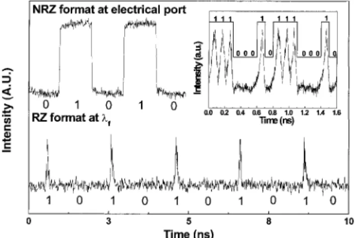
also be in phase under a dual-wavelength operation. Such an NRZ-to-RZ data-format conversion can be applied directly to the time-division multiplexing sys-tem to increase the bit rate. For instance, Fig. 5 shows an 8᎑bit NRZ-formatted signal (01010101) that modulates the tunable laser and the RZ-formatted output signal of the FPLD at f with a bit rate of
1 Gbps. The highest-ever-achieved bit rate of the FPLD-based NRZ-to-RZ data-format transformer is 10 Gbps. (See inset of Fig. 5.) The bit-error-rate mea-surement of the synchronously modulated FPLD un-der the injection of the 10᎑Gbps NRZ data stream 共223⫺ 1 PRBS兲 is carried out, as shown in Fig. 6. The
converted RZ is detected by a lightwave clock– data receiver, incorporating a high-gain avalanche photo-diode, a gain-controlled amplifier, and a clock– data recovery circuit. The received power is measured in the back-to-back NRZ data, and the back-to-back NRZ data are converted into RZ data at 10 Gbps. The power penalty at the 10⫺9 bit-error-rate level is 1.5 dB. Notably, an additional dc-bias current is re-quired to further extend the operating bandwidth of the FPLD.16The proposed configuration is similar to
that proposed by Yam and Shu.15However, the
con-figurations differ in some respects: (1) The use of the
EDFA in the external cavity here yields a larger SMSR 共⬎36 dB兲; (2) the FPLD-based data-format transformer is operated in the pulsed mode, by one’s setting the FPLD under a non-dc-current driving con-dition; and (3) a higher wavelength switching speed of as much as 10 GHz is reported, which compares favorably with the 300 KHz of the previous system. Nonetheless, the carrier and photon dynamics of the FPLD continue to limit the maximum speed of wave-length conversion.15
5. Conclusions
A novel FPLD-based configuration for translating an NRZ-format electrical signal into a wavelength-tunable, RZ-format optical signal was demonstrated. Gain switching the FPLD with a non-dc current and combining external-injection and self-feedback seed-ing promotes versatile functionality, includseed-ing the dual-wavelength operation, wavelength-conversion operation, and NRZ-to-RZ data-format transforma-tion. A Mach–Zehnder intensity modulator is used to encode the injection light by use of an NRZ-formatted PRBS pattern, yielding a 10᎑Gbps RZ-format optical signal from the proposed FPLD-based data trans-former. Properly setting the power and wavelength of the injection signal allows dual-wavelength and wavelength-conversion operations to be demon-strated. A maximum tuning range and SMSR of 30 nm and 36 dB are observed, respectively. The power penalty of 1.5 dB at 10 Gbps is measured for the NRZ-to-RZ data-format conversion. This configu-ration overcomes the drawbacks of the previous set-ups, such as the wavelength-dependent path in the grating-based self-feedback system, the difficulty in selecting identical FPLDs for an external-injection system, and the need for alignment of the optical path in the grating-based configuration.
The authors thank the National Science Council of Taiwan for partially supporting this research under contract NSC93-2215-E-009-007.
Fig. 5. Nformatted electrical data and FPLD-transformed RZ-formatted optical pulsed data at bit rate of 1 Gbps. The inset shows the NRZ- and FPLD-transformed data stream at 10 Gbps (by ad-dition of a dc-bias current of the FPLD).
Fig. 6. Bit-error-rate (BER) performance at 10 Gbps. The power penalty at the 10⫺9BER level is 1.5 dB.
References
1. L. Chusseau, E. Hemery, and J.-M. Lourtioz, “Period doubling in directly modulated InGaAsP semiconductor lasers,” Appl. Phys. Lett. 55, 822– 824 (1989).
2. H. F. Liu and W. F. Ngal, “Nonlinear dynamics of a directly modulated 1.55m InGaAsP distributed feedback semicon-ductor laser,” IEEE J. Quantum Electron. 29, 1668 –1675 (1993).
3. Y. Matsui, S. Kutsuzawa, S. Arahira, Y. Ogawa, and A. Suzuki, “Bifurcation in 20᎑GHz gain-switched 1.55᎑m MQW lasers and its control by CW injection seeding,” IEEE J. Quantum Electron. 34, 1213–1223 (1998).
4. K. K. Chow, C. Shu, and H. F. Liu, “All-optical control of clock frequency division using injection-locked Fabry–Perot laser diode,” Electron. Lett. 39, 1136 –1138 (2003).
5. H. K. Tsang, L. Y. Chan, S. P. Yam, and C. Shu, “Experimental characterization of dual-wavelength injection-locking of a Fabry–Perot laser diode,” Opt. Commun. 156, 321–326 (1998). 6. L. Y. Chan, C. K. Chan, D. T. K. Tong, F. Tong, and L. K. Chen, “Upstream traffic transmitter using injection-locked Fabry– Perot laser diode as modulator for WDM access networks,” Electron. Lett. 38, 43– 45 (2002).
7. C. W. Chow, C. S. Wong, and H. K. Tsang, “All-optical NRZ to RZ format and wavelength converter by dual-wavelength in-jection locking,” Opt. Commun. 209, 329 –334 (2002). 8. M. Owen, M. F. C. Stephens, R. V. Penty, and I. H. White,
“All-optical 3R regeneration and format conversion in an inte-grated SOA兾DFB laser,” in Proceedings of Optical Fiber
Com-munication Conference, T. Li, ed. (Institute of Electrical and
Electronics Engineers, New York, 2000), pp. 76 –78.
9. S. Bigo, E. Desurvire, S. Gauchard, and E. Brun, “Bit-rate enhancement through optical NRZ-to-RZ conversion and pas-sive time-division multiplexing for soliton transmission sys-tems,” Electron. Lett. 30, 984 –985 (1994).
10. S. Bigo, E. Desurvire, and B. Desruelle, “All-optical RZ-to-NRZ format conversion at 10 Gbit兾s with nonlinear optical loop mirror,” Electron. Lett. 30, 1868 –1869 (1994).
11. K. J. Blow, N. J. Doran, B. K. Nayar, and B. P. Nelson, “Two-wavelength operation of the nonlinear fiber loop mirror,” Opt. Lett. 15, 248 –250 (1990).
12. D. Norte and A. E. Willner, “Experimental demonstrations of all-optical conversions between the RZ and NRZ data formats incorporating noninverting wavelength shifting leading to for-mat transparency,” IEEE Photon. Technol. Lett. 8, 712–714 (1996).
13. J. Horer and E. Patzak, “Large-signal analysis of all-optical wavelength conversion using two-mode injection-locking in semiconductor lasers,” IEEE J. Quantum. Electron. 33, 596 – 608 (1997).
14. S. Bouchoule, N. Stelmakh, M. Cavelier, and J.-M. Lourtioz, “Highly attenuating external cavity for picosecond-tunable pulse generation from gain兾Q-switched laser diodes,” IEEE J. Quantum Electron. 29, 1693–1700 (1993).
15. S. P. Yam and C. Shu, “All-optical wavelength switching in a semiconductor laser using self-seeding and external injection-seeding,” Appl. Phys. Lett. 72, 1024 –1026 (1998).
16. L. P. Barry, P. Anandarajah, and A. Kaszubowska, “Optical pulse generation at frequencies up to 20 GHz using external-injection seeding of a gain-switched commercial Fabry–Perot laser,” IEEE Photon. Technol. Lett. 13, 1014 –1016 (2001).