Design of fuzzy power system stabilisers for
multimachine power systems
Y.-Y. HSU, BSC, MSC, PhD C.-H. Cheng, BSc, MSc
Indexing terms: Stabilisers, Power system protection, Mathematical techniques
Abstract: A new type of power system stabiliser based on fuzzy set theory is proposed to improve the dynamic performance of a multimachine power system. To have good damping character- istic over a wide range of operating conditions, speed deviation (Am) and acceleration ( A h ) of a machine are chosen as the input signals to the fuzzy stabiliser on that particular machine. These input signals are first characterised by a set of lin- guistic variables using fuzzy set notations. The fuzzy relation matrix, which gives the relationship between stabiliser inputs and stabiliser output, allows a set of fuzzy logic operations that are per- formed on stabiliser inputs to obtain the desired stabiliser output. Since only local measurements are required by the fuzzy stabiliser on each gener- ating unit, the proposed stabiliser is of decentral- ised output feedback form and is easy for practical implementation. The effectiveness of the proposed fuzzy stabiliser is demonstrated by a multimachine system example.
1 Introduction
The application of power system stabilisers (PSS) to improve the dynamic performance of a power system has been the focus of extensive studies for more than two decades [l-81. The most widely employed power system stabiliser is the lead-lag PSS where the gain settings are fixed at certain values which are determined under partic- ular operating conditions. Since the operating point of a power system drifts as a result of continuous load changes or unpredictable major disturbances such as a three-phase fault, it is desirable to adapt the stabiliser parameters in real-time based on on-line measurements in order to maintain good dynamic performance over a wide range of operating conditions. This motivates the development of a self-tuning power system stabiliser
Although the self-tuning PSS is capable of offering better dynamic performance than a fixed-gain PSS, it suffers from a major drawback of requiring model identi- fication in real-time which is very time consuming, espe- cially for a microcomputer with limited computational capability.
[9-141.
Paper 7206C (P4, P9), first received 14th August and in revised form 19th December 1989
The authors are with the Department of Electrical Engineering, Nation- al Taiwan University, Taipei, Taiwan
IEE PROCEEDINGS, Vol. 137, P t . C , N o . 3, M A Y 1990
In this paper, a new type of power system stabiliser, which does not require real-time model identification, is developed using fuzzy set theory [lS]. The proposed fuzzy PSS uses two real-time measurements Am (generator speed deviation) and A h (acceleration) as the input signals. To determine stabiliser output, these input signals are first described by some linguistic variables such as L P (large positive), M P (medium positive), SP (small positive), V S (very small), SN (small negative), M N (medium negative), and L N (large negative), using fuzzy set notation. A fuzzy relation matrix which gives the relationship between stabiliser inputs and stabiliser output is then developed using membership functions. A set of fuzzy logic operations are performed to yield the desired stabiliser output based on this fuzzy relation matrix. The effectiveness of the proposed fuzzy PSS is demonstrated by examining the dynamic performance of a multimachine power system subject to a major dis- turbance.
The main features of the work are summarised as follows.
(a) The developed fuzzy PSS is very efficient and can be easily implimented on a microcomputer since it does not require real-time model identification.
(b) The fuzzy stabiliser developed in this paper is of decentralised output feedback form since only local mea- surements (Am and A h ) are employed as the inputs to each PSS.
(c) Results from the application of the fuzzy PSS to a multimachine system reveal that the fuzzy PSS can offer good dynamic performance over a wide range of oper- ating conditions.
2
Some basic definitions and mathematical operations of fuzzy sets are first described [lS].
Introduction t o fuzzy set theory
2.1 Fuzzyset
Let X be a collection of objects (X is the universal set), then a fuzzy set A in X is defined to be a set of ordered pairs
A = {(x, pLA(x))
I
x Ex>
(1)where pLA(x) is called the membership function of x in A. Note that the membership-function p A ( x ) denotes the degree to which x belongs to A and is normally limited to values between 0 and 1. A high value of p;i(x) implies that it is very likely for x to be in A. Elements with a zero degree of membership are normally not listed. If we limit the values of the membership function to be either 0 or 1, then A becomes a crisp (nonfuzzy) set.
2.2 The AND operator (The intersection of two fuzzy sets)
Let A and B be two fuzzy sets with membership functions
pA(x) and pB(x), respectively. The membership function of
the intersection (AND), C = A n B, is defined by
PdX) = min ( P A X ) PAX)) x E
x
(2) 2.3 The OR operator (The union of two fuzzy sets)Let A and B be two fuzzy sets with membership functions pA(x) and pB(x), respectively. The membership function of the union (OR), D = A U B, is defined by
P&)
= max ( P A X ) PAX)) x Ex
(3) 2.4 The NOT operator (The complement of a fuzzyset)
Let A be a fuzzy set with membership function pA(x). The membership function of the complement of A , is defined by
P C k ) = 1 - P A X ) x E
x
(4)2.5 Fuzzy relation
Let A and B be two fuzzy sets with membership functions pA(x) and
PAX),
respectively. A fuzzy relation R from A toB can be visualised as a fuzzy graph and can be charac-
terised by the membership function p R ( x , y ) which satisfies the composition rule as follows:
P A Y ) = max (min (PI&? Y ) P A X ) ) ) ( 5 )
X
3 Design of the fuzzy power system stabiliser
To make the designed PSS capable of providing the desired system damping under disturbance conditions, some state variables representative of system dynamic performance must be taken as the input signals to the fuzzy PSS. In this work, generator speed deviation (Am) and acceleration ( A h ) are chosen to be input signals of the fuzzy PSS since our previous experience indicated that, under disturbance conditions, dynamic performance of the system could be evaluated by examining the response curves of these two variables.
In practice, only shaft speed (Am) is readily available [16]. The acceleration signal ( A h ) can be derived from the speed signals measured at two successive sampling instants using the following equation [ 17, 181 :
A h ( k ) = (Ao(k) - Am(k - l))/AT (6)
where A T is the sampling interval. To limit the impact of noise and minimise torsional interaction, low pass or band-reject filters are required in practical implementa- tion [l].
To determine the stabiliser output from the measured system variables Am and A h , a fuzzy relation matrix R, which gives the relationship between the fuzzy set charac- terising stabiliser inputs and the fuzzy set characterising stabiliser output, is first established and stored in com- puter memory. The fuzzy PSS proceeds as follows to evaluate the desired output signal.
Step 1 : Use membership functions to represent stabili- ser inputs Am and A h in fuzzy set notation.
Step 2: Use the composition rule in eqn. 5 to deter- mine the membership function of the stabiliser output
Step 3 : Determine a proper stabiliser output from the
vi,
*membership function of the output signal. 234
Details of the above procedures are addressed in the fol- lowing discussions.
3.1 Establish the fuzzy relation matrix
A fuzzy relation matrix must be set up and stored in computer memory. A set of decision rules relating stabili- ser inputs to stabiliser output are first compiled based on our previous experience with stabiliser design [5-8, 11-13]. These decision rules are expressed using linguistic variables such as large positive ( L P ) , medium positive
( M P ) , small positive (SP), very small ( V S ) , small negative
( S N ) , medium negative ( M N ) , and large negative ( L N ) .
For example, a typical rule reads as follows: Rule 1 If AW is LP and A h is L N ,
then V,, (stabiliser output) should be V S . (7) Through the combination of the two input signals AW and A h , there will be 49 decision rules in all. The most convenient way to present these decision rules is to use a decision table as shown in Table 1. The decision table, which has been adopted from Reference 19, is found to be applicable to various problems involving decision making.
Table 1 : Decision table
speed Acceleration, AW deviation, Aw LN M N SN VS SP M P LP LP VS* SP M P LP LP LP LP M P SN VS SP M P M P LP LP SP M N SN VS SP SP M P LP vs M N M N SN VS SP M P M P SN LN M N SN SN VS SP M P M N LN LN M N M N SN VS SP LN LN LN LN LN M N SN VS * Rule 1 .
It is observed from Table 1 that each entry represents a particular rule. Using fuzzy set notations, the decision table in Table 1 can be converted into the fuzzy relation matrix in Table 2 where stabiliser output obtained by applying a particular rule is expressed in membership functions. For example, Rule 1 in eqn. 7 now becomes
Rule 1‘ If Am is L P and A h is L N ,
then the stabiliser output V,,, can be charac- terised by the fuzzy set { ( L N , O.O), ( M N , O.O),
( S N , 0.51, ( V S , I), ( S P , 0.9, ( M P , O), ( L P , 0)). (8) Note that in Rule 1’ we are still not certain whether AW is
L P and A h is L N . The degree of belief in the ‘If’ part
(‘condition part’) of the rule can be specified through the use of membership functions as described below.
3.2 Specify the membership functions for stabiliser inputs
To express the stabiliser inputs in linguistic variables LP,
M P , S P , V S , S N , M N , and L N , the measured stabiliser
inputs Am and A h are first normalised based on previous experience. AW 0.0 1 Amu = - A h 0.001 A h ” = - (9)
Using these normalised quantities, stabiliser inputs can be described by membership functions for the linguistic IEE PROCEEDINGS, Vol. 137, P t . C , N o . 3, M A Y 1990
0 0 0 0 0 0 0 0 0 0 0 0 0 0 0.5 0 0 0 0 0 0 0.5 0.5 0 0 0 0 0 1 0.5 0 0 0 0 0 1 1 0.5 0.5 0 0 0 1 1 1 1 0.5 0 0 0 0 0 0 0 0 0 0.5 0 0 0 0 0 0 1 0.5 0 0 0 0 0 1 1 0.5 0 0 0 0 0.5 1 0.5 0.5 0 0 0 0.5 0.5 1 1 0.5 0 0 0.5 0.5 0.5 0.5 1 0.5 0 0.5 0 0 0 0 0 0 1 0.5 0 0 0 0 0 0.5 1 0.5 0 0 0 0 0.5 0.5 1 0.5 0 0 0 0 0.5 1 1 0.5 0 0 0 0 0.5 0.5 1 0.5 0 0 0 0 0 0.5 1 0.5 1 0.5 0 0 0 0 0 0.5 1 0.5 0 0 0 0 0 0.5 1 0.5 0.5 0 0 0 0 0.5 1 0.5 0 0 0 0 0.5 0.5 1 0.5 0 0 0 0 0 0.5 1 0.5 0 0 0 0 0 0.5 1 0.5 1 0.5 0 0 0 0 0 0.5 1 0.5 0.5 0 0 0 0 0.5 1 1 0.5 0 0 0 0 0.5 1 0.5 0.5 0 0 0 0 0.5 1 0.5 0 0 0 0 0 0.5 1 0 0 0 0 0 0 0 0.5 1 0.5 0.5 0.5 0.5 0 0 0.5 1 1 0.5 0.5 0 0 0 0.5 0.5 1 0.5 0 0 0 0 0.5 1 1 0 0 0 0 0 0.5 1 0 0 0 0 0 0 0.5 0 0 0 0 0 0 0.5 0 0 0 0.5 1 1 1 1 0 0 0 0.5 0.5 1 1 0 0 0 0 0 0.5 1 0 0 0 0 0 0.5 0.5 0 0 0 0 0 0 0.5 0 0 0 0 0 0 0 0 0 0 0 0 0 0 variables, as shown in Table 3. Note that only the mem-
bership functions for nine different values of Aw,, and Ah,, are given in Table 3. For a value of Am, or Ah,, which is not listed in Table 3, linear interpolation must be employed to determine the membership functions.
Let us demonstrate the use of Table 3 by an example. At a particular sampling instant, let the sampled stabili- Table 3: Membership functions for stabiliser inputs
Normalised inputs Membership functions
Aw, or AW, LN M N SN VS SP M P LP -1 .o -0.2 -0.1 -0.05 0 0.05 0.1 0.2 1 .o 1 0.7 0.5 0.3 0 0 0 1 0.9 0.7 0.5 0.2 0 0 0.8 1 0.9 0.7 0.4 0.2 0 0.6 0.8 1 0.9 0.6 0.4 0.2 0.4 0.6 0.8 1 0.8 0.6 0.4 0.2 0.4 0.6 0.9 1 0.8 0.6 0 0.2 0.4 0.7 0.9 1 0.8 0 0 0.2 0.5 0.7 0.9 1 0 0 0 0.3 0.5 0.7 1
1EE PROCEEDINGS, Vol. 137, Pt. C , N o . 3, M A Y 1990
ser inputs be, say, Am,, = 0.2 and Ah,, = -0.1. From Table 3, the two stabiliser inputs can be described by the following fuzzy sets.
Aw,,: { ( L N , 0), ( M N , 0), ( S N , 0.2), ( V S , OS), A h ” : { ( L N , 0.8), ( M N , l), ( S N , 0.9), ( V S , 0.7), ( S P , 0.7), ( M P ,
0.9,
(LP, 1)) (SPY 0.41, ( M P , 0.21, (LP, 0,) (1 1) (12)3.3 Determine the membership function of stabiliser output
Using the previous example, we intend to demonstrate the use of the composition rule to determine the member- ship function of the stabiliser output. It is obvious from Table 2 that there are 49 rules which can be used to gen- erate the desired stabiliser output. Consider Rule 1 in eqn. 7 or its equivalent, Rule l’, in eqn. 8. The ‘action’ part (the ‘Then’ part) of the rule has been represented in fuzzy set notations using membership functions but the ‘condition’ part (the ‘If‘ part) is still to be represented 235
using the fuzzy set notation. An observation of Rule 1' reveals that the condition part consists of two predicates 'Am is LP' and ' A h is LN' combined together by an 'AND' operator. From eqn. 2 we have the membership value for the condition part.
p(xl) = p('Am is LP' and ' A h is LN')
= min (p('Am is LP') &Ah is LN')) (13) From eqns. 11 and 12 we have ~ ( ' A o is LP') = 1 and
p('Ah is LN') = 0.8. Thus the membership value of the condition part is
p(xl) = min (1, 0.8)
= 0.8 (14)
Given the membership values for the 'condition' part and the fuzzy relation matrix, the membership values for the stabiliser output characterised by the seven linguistic variables L N , M N , S N , V S , SP, M P , LP can be obtained using eqn. 5. For example, the membership value for the linguistic variable L N can be computed as follows.
P V m . i ( L N ) = min ( P R ( x l , L N ) pL(xl)) = min (0, 0.8)
= O (15)
Note that this is the membership value of the stabiliser output 'LN' if only Rule 1 exists. To take the 49 rules in Table 3 into account, the membership values for the 'con- dition' part of all the other 48 rules &), i = 2,
. .
.
,
49, must be determined in the same way as we did in eqn. 14 for p(xl). Thus, the final value for stabiliser output ' L N can be evaluated using eqn. 5pVm(LN) = max (min ( p R ( x i 9 L N ) PL(%))) (16)
PV,(MN), CLV,(SN)' PYrn(VS)' P Y r n ( W ' PVrn(MP)? and X i
The membership values for all the other six variables:
pVm(LP) can be computed in exactly the same way. The
final results for the preceding example are as follows:
pvrn(LN) = 0.5 pV,(MN) = 0.7 pV,(SN) = 0.8 ( ~ 0 0 6 2 5
/
0 0085+jO 0720 '
1
pvm(VS) = 0.9 2 9 + j O 1008'
J00:861' pvm(SP) = 1.0 pV,(MP) = 0.9 p,,(LP) = 0.7 - @8/2=Jolo45
812 = J O 0745 1 la2303.4 Determine the stabiliser output
Once the membership values for stabiliser output have been computed, a suitable algorithm must be employed to determine the stabiliser output signal. The algorithm adopted in this work is the 'maximum algorithm' in which the signal with largest membership value is chosen as the stabiliser output signal. Using eqn. 17, the stabili- ser output for our example is SP. Since the excitation system can take only numerical values of V,
,
the stabili- ser output expressed in linguistic terms must be con- verted back to numerical values before it can be fed into the excitation system. The conversion table as shown in Table 4 has been compiled based on the stabiliser signals obtained in our previous work on stabiliser design. A dif- ferent set of numerical values can be selected and differ- ent dynamic responses will be obtained. The difference 236\ @
will however be insignificant since the stabiliser signal must be within the narrow range from -0.12 p.u. to 0.12 p.u. The table is stored in computer memory as a look-up table. It is observed from Table 4 that the numerical value of stabilising signal for our example is 0.02 p.u.
@
0 032 + j O 161
Table 4: Conversion table from linguistic variables t o
numerical values LN MN SN VS SP M P LP @ 230113 8 6/2:jO 153 0 0 3 9 + ~ 0 170 812 = j O 179 V,,,, P.U. -0.10 -0.04 -0.02 0 0.02 0.04 0.10 4 Example
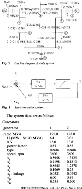
Consider a nine-bus, two machine-infinite bus system as shown in Fig. 1 [2]. Fig. 2 depicts the block diagram for the excitation system [2]. The detailed model describing shaft dynamics is not included since the problem of sub- synchronous resonance [20-211 is beyond the scope of the present work.
0 load 010 + A
Jq6!):ki
0 017+jO 092 g J rload 7 9230 kV 16 51230 100 5 7 6
Fig. 1 One line diagram ofstudy system
I
I
Fig. 2 Static excitation system
The system data are as follows. Generators generator 1 2 rated MVA H (MW
.
S/100 MVA) KV power factor type speed, rpm XI xq xb x i , leakage4 0
T i o x d 192.0 6.4 18.0 0.85 steam 3600 0.8958 0.1198 0.8645 0.1969 0.0521 6.00 0.535 128.0 3.01 13.8 0.85 steam 3600 1.3125 0.1813 1.2578 0.25 0.0742 5.89 0.600Excitation systems
Loads ( M V A ) load A = 125 + j 5 0 load B = 90 + j 3 0 load C = 100
+
j35The response curves for the system without PSS are shown in Fig. 3. It is observed from Fig. 3, that system damping is poor and it is necessary to install stabilisers in order to have good dynamic performance. In the present study, three different control schemes are investigated for the purpose of comparison.
0 012
I
0008-
om -0 008:
00042
-om4 -0 0121 time, s a 0 0121 0 0085
0004 a -0 004 -0 008 -0 012 3- 000 Fig. 3 a Aw, b Aw2System response of generators without stabilisers
(1) Both generators are equipped with a conventional lead-lag PSS with the transfer function [ 121
10s (1
+
0.568s)’ 1+
10s (1+
0.0227s)’ G(s) =-
.
0 012c a 0 0121 -0 0121 b Fig. 4 a Awl b Aw2IEE PROCEEDINGS, Vol. 137, Pt. C , N o . 3, M A Y 1990
System response of generators with conventional stabilisers
(2) Generator 1 is equipped with a fuzzy PSS, while Generator 2 is not equipped with a PSS.
( 3 ) Both generators are equipped with fuzzy stabilisers. The dynamic responses following a 4 cycle three-phase fault at bus 7 are depicted in Figs. 4-6.
10r -8
63
-1 0 0 0 8 1 6 2 4 3 2 4 0 4 8 5 6 6 4 7 2 8 0 t i m e , s aI $ ,
I I I , I , I I I 10 0 0 8 1 6 2 4 3 2 4 0 4 8 5 6 6 4 7 2 8 0 t1me.s b 0 12r -0121 I I I I I I I I I I 0 0 0 8 1 6 2 4 3 2 4 0 4 8 5 6 6 4 7 2 8 0 time, sSystem response with fuzzy stabilisers onfirst generator
C Fig. 5 a Awl b Aw2 c vm, 5 Discussion
From the response curves in Figs. 3-6, the following observations can be made:
( a ) Among the three proposed control schemes, the one with both units equipped with fuzzy stabilisers pro- vides the best damping characteristic.
( b ) The dynamic responses of the system with only one generating unit equipped with a fuzzy PSS are still much better than those obtained by using conventional stabili- sers.
( c ) It can be observed from the response curve of Aw2
in Fig. 5 that, when only generator 1 is equipped with a fuzzy stabiliser, unit 2 will benefit from this fuzzy stabili- ser via the transmission links between the two units.
(d)
When there is a fuzzy stabiliser on each unit, the two decentralised fuzzy stabilisers co-operate with each other very well in their efforts to damp out system oscil- lations under disturbance conditions.(e) As evidenced by the response curves in Figs. 5-6, only moderate gains are required for the fuzzy stabiliser.
a -4 -6 -8 O l’F -
-
- 0 0 0 8 16 2 4 3 2 L O 4 8 5 6 6 4 7 2 8 0 time,s C 0 1 2 r 0 0 0 8 1 6 2 4 3 2 4 0 L 8 5 6 6 4 7 2 8 0 t i m e , s dSystem response with fuzzy stabilisers on both generators Fig. 6
a Am, c , v,
6 Am2 d vm,
multimachine power system over a wide range of oper- ating conditions. The fuzzy PSS generates its output signal based on some fuzzy decision rules relating stabili- ser input signals with stabiliser output. These fuzzy deci- sion rules have been gathered through our previous
experience with stabiliser design. Results from this work reveal that, under disturbance conditions, better dynamic performance can be achieved using the proposed fuzzy stabiliser than a conventional stabiliser. The proposed fuzzy stabiliser is very simple for practical implementa- tion since the decentralised output feedback control law developed in this paper requires only local measurements within each generating unit. Moreover, it is superior to a self-tuning stabiliser because it does not require real-time model identification as the self-tuning PSS does. Thus, it is easily implemented on a microcomputer.
7 1 2 3 4 5 6 7 8 9 References
LARSEN, E.V., and SWANN, D.A.: ‘Applying power system stabili- sers’, IEEE Trans., 1981, PAS-100, pp. 3017-3046
ANDERSON, P.M., and FOUAD, A.A.: ‘Power system control and stability’ (Iowa State University Press, Ames, Iowa, 1977) DEMELLO, F.P., NOLAN, P.J., LASKOWSKI, T.F., and UNDRILL, J.M. : ‘Coordinated application of stabilizers in multi- machine power systems’, IEEE Trans., 1980, PAS-99, pp. 892-901 DEMELLO, F.P., and CONCORDIA, C.: ‘Concepts of synchro- nous machine stability as effected by excitation control’, IEEE Trans., 1969, PAS-88, pp. 316-329
CHAN, W.C., and HSU, Y.Y.: ‘An optimal variable structure stabil- izer for power system stabilization’, I E E E Trans., 1983, PAS-102, HSU, Y.Y., and HSU, C.Y.: ‘Design of a proportional-integral power system stabilizer’, IEEE Trans., 1986, PWRS-1, pp. 46-53 HSU, Y.Y., SHYUE, S.W., and SU, C.C.: ‘Low frequency oscil- lations in longitudinal power systems: Experience with dynamic sta- bility of Taiwan power system’, IEEE Trans., 1987, PWRS-2, pp. HSU, Y.Y., and SU, C.C.: ‘Application of power system stabilizer on a power system with pumped storage plant’, IEEE Trans., 1988, XIA, D., and HEYDT, G.T.: ‘Self-tuning controller for generator
pp. 1738-1746
92-100
PWRS-3, pp. 80-86
excitation’, I E E E Trans., 1983, PAS-102, gp. 1877-1885
10 CHENG, S.J., CHOW, Y.S., MALIK, O.P., and HOPE, G.S.: ‘An adaptive synchronous machine stabilizer’, I E E E Trans., 1986, 11 HSU, Y.Y., and LIOU, K.L.: ‘Design of self-tuning PID power system stabilizers for synchronous generators’, IEEE Trans., 1987, 12 WU, C.J., and HSU, Y.Y.: ‘Design of self-tuning PID power system stabilizer for multimachine power systems’, IEEE Trans., 1988, 13 HSU, Y.Y., and WU, C.J.: ‘Adaptive control of a synchronous
machine using the auto-searching method’, I E E E Trans., 1988, 14 CHANDRA, A., MALIK, O.P., and HOPE, G.S.: ‘A self-tuning controller for the control of multi-machine power systems’, I E E E Trans., 1988, PWRS-3, pp. 106-1071
15 ZIMMERMANN, H.J.: ‘Fuzzy Set Theory and Its Applications’
(Kluwer-Nijhoff Publishing Company, 1985)
16 WATSON, W., and MANCHUR, G.: ‘Experience with supplemen- tary damping signals for generator static excitation systems’, IEEE Trans., 1973, PAS-92, pp. 199-203
17 HIYAMA, T. : ‘Rule-based stabiliser for multimachine power system’. Paper 89 SM 691-7 PWRS, presented at the IEEEjPES 1989 Summer Meeting
18 HIYAMA, T.: ‘Application of rule-based stabilising controller to electrical power system’, I E E Proc. C., 1989,136, (3), pp. 175-181 19 TANG, K.L., and MULHOLLAND, R.J.: ‘Comparing fuzzy logic
with classical controller designs’, IEEE Trans., 1987, SMC-17, pp. 1085-1087
20 WANG, L., and HSU, Y.Y.: ‘Damping of subsynchronous reson- ance using excitation controllers and static VAR compensators: a comparative study’, IEEE Trans., 1988, EC-3, pp. 6-13
21 HSU, Y.Y., and WU, C.J.: ‘Design of PID static VAR controllers for the damping of subsynchronous oscillations’, IEEE Trans., 1988,
- PWRS-1, pp. 101-109 EC-2, pp. 343-348 PWRS-3, pp. 1059-1064 PWRS-3, pp. 1434-1440 EC-3, pp. 21G216