ELSEVIER Journal of Crystal Growth 154 (1995) 351-363
, . . . C R Y S T A L G R O W T H
Volume change effect on the salt-finger stability of directionally
solidifying ammonium chloride solution
Y.C. Lee, Falin Chen*
Institute of Applied Mechanics, National Taiwan University, Taipei, Taiwan, ROC Received 26 December 1994; accepted 10 May 1995
Abstract
The effect of the volume change due to phase transformation on the stability of salt-finger convection of directionally solidifying NH4CI aqueous solution cooling from below is investigated. The basic flow, induced by the volume change, not only changes the morphology and the depth of the dendritic mushy layer, but also influences the stability of salt-finger convection. A new mathematical model is proposed, which differs from the previous one mainly on the dynamical condition at the melt/mush interface. This difference not only leads to a less stable state, but can also be crucial to the dynamical behavior of the oscillatory instability mode since the convection cells of this mode are coupled viscously through the interface. In the discussion, special emphasis is placed on the volume change effect on the instability mode competition, which may be influential to the stability characteristics of the subsequent plume convection.
1. Introduction
Recently, a large research effort has been made to investigate the convective flows in the directional so- lidification of ammonium chloride solution cooling from below because of their significant influence on the composition as well as the structure of the resul- tant casting; especially the analogy between the flow- induced chimneys in the dendritic mushy zone and the freckles in the directionally solidified casting of metallic alloy, which causes a deleterious effect on the mechanical strength of the casting [ 1-10]. The de- tails of the convective flows in solidifying 26% NH4CI solution are available in Chen and Chen [3]. Here, we briefly outline the principal flows in the following. At the beginning of solidification, due to the ejection of the lighter and cooler fluid from the solidification
* Corresponding author.
front, the salt-finger convection occurs. As the mushy- layer grows to a certain height and, meanwhile, the salt-finger convection becomes more vigorous, con- vective plumes sparsely distributed on the plane of the solidification front come directly from the interior of the mush, leading to the formation of chimneys. Later on, the salt-finger convection fades out gradually while the plume convection becomes increasingly prevalent. The plume convection is believed to correspond to a subcritical mushy-layer mode instability [6] resulting from the perturbation of nonlinear salt-finger convec- tion [ 10]. This scenario is supported by the experi- ment of Sample and Hellawell [ 1 ] that new plumes can be generated by withdrawing liquid in the vicin- ity above the freezing front. Accordingly, the stability of salt-finger convection has a close relation with the chimney formation.
Due to the importance of the salt-finger convection as stated above, several investigations have been de- 0022-0248/95/$09.50 @ 1995 Elsevier Science B.V. All rights reserved
352
Y C Lee, E Chen/Journal of Crystal Growth 154 (1995) 351-363voted to studying the stability characteristics of this flow. Tait & Jaupart [2] investigated experimentally the onset of salt-finger convection by increasing the viscosity of 28% NH4CI solution and found that the onset of salt-finger convection occurs largely in the compositional boundary-layer above the melt/mush interface (the so-called boundary-layer mode convec- tion) while the fluid in the mush does not participate in the initial instability. Worster [5] in a linear stability analysis investigated the stability of the mushy-layer mode convection, a convection circulating between the melt and the mush, for a special alloy. In another linear stability analysis Chert, Lu and Yang [ 10] concluded that the onset of salt-finger convection of NH4C1 solu- tion is of boundary-layer mode and speculated that as the salt-finger convection becomes fully nonlinear the onset of the plume convection is induced. In another stability analysis Nandapurkar et al. [ 11 ] solved a set of dimensional equations particularly for the lead-tin alloy without considering the interaction between con- vection and solidification in the mushy layer. Their re- sults, accordingly, are not relevant to the present study. In the present paper, we examine the stability of salt-finger convection under the influence of volume change. The volume change, or the density change due to phase transformation, is significant in some al- loys. As volume change occurs, either shrinking or expanding, a uniform flow is induced, which in turn influences the morphological instability of single com- ponent fluid [ 12]. For a binary solution, the induced flow not only changes the morphology of the dendritic mushy layer, but also varies the stability characteristics of the salt-finger convection. In the following paper, we present the mathematical formulation in Section 2, which is different from that of Worster [5] and Chen, Lu and Yang [ 10] in several respects. In Section 3 the basic state solution due to volume change is discussed. In Section 4 the linearized equations and method of solution are presented. In Section 5 the linear stability results are shown; special emphasis is placed on the convection modes and their stability criteria. In Sec- tion 6, the conclusion is provided.
2. Mathematical formulation
Consider a mushy layer lying above a solid region and below a semi-infinite melt region. A binary solu-
tion of concentration Coo and temperature T ~ is direc- tionally solidified from below and both the melt/mush and mush/solid interfaces move upwards with a con- stant velocity V. The mushy layer extends from z = 0 to z = h, where h is the position of the melt/mush interface which is to be determined as part of the so- lution. The temperature at the mush/solid interface is fixed at the eutectic temperature TE. Two sets of equations are required to describe the fluid motion of the system. Each set consists of the conservation of mass, momentum, heat, and solute, which are de- scribed in Fowler [ 13] and Chiareli and Worster [ 14] for the mushy layer and in McFadden and Coriell [ 15 ] for the fluid layer. The Boussinesq approximation is applied to the momentum equations of both layers. We nondimensionalize the fluid velocities with the prescribed interface velocity V, distances with
Ktl/V,
time with Xtl/V 2, density with Pl, and pressure with/3ACplgKtl/V.
Here xtl is the thermal diffusivity of the fluid,/3 =/3* - F a * , / 3 * and a* are solutal and thermal expansion coefficients, respectively, F is the slope of the liquidus curve, which is assumed to be a constant, AC = Coo - CE, CE is the eutectic concentration, Pl is the density of the liquid, and g is the gravitational acceleration. By assuming the physical properties, ex- cept the density, of the fluid and solid are identical and by taking the Galilean transformation with respect to the moving interface, we obtain the following dimen- sionless equations. In the fluid layer h < z < c~, we haveV . u = 0 , (1)
[0~ -- ~ ] 0 q-U" V0 = V20,
(2)- O + u . VO = eV2O, (3)
o-
Oz
+ u . V u= V2U + RTOek -- Rc (Oek + ~ . V p ) ,
(4) where u = (u, v, w) is the velocity vector in Cartesian coordinate. The dimensionless temperature and con- centration are defined asT
- TL(Coo)
C - Coo
0 = , o = ~ , (5)
YC. Lee, E Chen/Journal of Crystal Growth 154 (1995)351-363 353 where AT = FAC = TL(Coo) - TE, TL(Co~) is the
liquidus temperature corresponding to Coo, e = Kel/Ktl is the Lewis number, Kcl is the solutal diffusivity of the melt, o- = v/Ktl is the Prandtl number, ek is the unit vector in the vertical direction, p is the pressure, RT and Rc are thermal and solutal Rayleigh numbers given by
gcr * A TH 3 gfl* A C H 3
RT - - - , Rc --- , (6)
Ktl/2 Ktl p
in which v is the kinematic viscosity and H =
Ktl/V
isthe characteristic length. In the mushy-layer 0 < z < h, we have [ 13 ]
(oo)
fit Oz p + V . ( p u ) = O, (7)fit
Oz
[ p ( O - C ) x ] + V . [ p u ( O - C ) ] = eV. (xpVO), ( 8 ) = V20 +.T" ~ [p(1 - X ) ] , (9) u - - = - R m ( V p + Oek), (10) n ( x )where u is the barycentric velocity defined as u = X ut in which u t is the liquid velocity in the mush, X is the liquid mass fraction, and H is the dimensionless per- meability of the mushy zone. Note that when volume- change vanishes, X is also the liquid volume fraction (or porosity). In above equations, we also note that C = (Cs - COO)/AC is the concentration ratio, Cs is the concentration of solid, ~ = £ / c A T is the Stefan number,/2 is the latent heat of fusion, c is the specific heat, and the Rayleigh number for the mushy layer is given by
Rm - g ~ A C I I o H , (11)
Ktl/2
in which 110 is the reference permeability. Eqs. ( 7 ) - (10) are derived according to Fowler's approach [ 13 ], which can also be obtained from the formulation of Chiareli and Worster [ 14] where they formulated the
equations in terms of volume fraction and the Darcy velocity defined as UD = p x u I. In Eq. 9, we also as- sume the heat capacity per unit volume of both the liquid and solid phases to be the same. The liquidus relation 0 -- O shall be applied in the mushy layer in which the thermodynamic equilibrium condition is as- sumed to be valid [6]. In Eqs. ( 7 ) - ( 9 ) , the density is given as
ps 1
P = Pl 1 + Y X ' (12)
where y = (ps - p l )/p~ is a constant corresponding to the volume change and Ps and pl are densities of the solid and the liquid, respectively. I f y < 0, the solid density is less than the melt density so that solidifica- tion results in an expansion as well as an upward flow, and vice versa for y > 0.
The boundary conditions at the z --4 e~ are
0 --~ 0oo, (13a)
O ~ 0, (13b)
w --~ - % (13c)
Eq. (13c) corresponds to the flow induced by the vol- ume change, see also Eq. (17) of Section 3. At the melt/mush interface z = h, the boundary conditions a r e 0 = O, (14a) n - V 0 = n . V O , (14b) In .u] = 0 , (14c) [0] = 0, (14d) [n. VO] = 0, (14e) X = 1, (14f) Ow
~
Rcplh+ + 2 ~ z z Ih+ = - 7 - [ R m P I h - , ( 1 4 g ) au2 A x / ~ . , h+ = ~ t U 2 1 h + -- U 2 l h - ) , (14h)7z
V I I ( I )where the square brackets denote the jump of the en- closed quantity across the interface, n is a unit vec- tor normal to the interface, and u2 is the plane veloc- ity vector denoting (u, v). In above boundary condi- tions, Eq. (14a) is the liquidus relation applying at the interface, Eq. (14b) is the marginal equilibrium
354 YC. Lee, E Chen/Journal of Crystal Growth 154 (1995) 351-363
condition [16], Eq. (14c) is the continuity of nor- mal velocity, Eqs. (14d) and (14e) are continuities of temperature and heat flux, respectively, Eq. (14f) is an enforced condition assuming the solid at the in- terface vanished, Eq. (14g) is the continuity of nor- mal stress including the deviatoric stress, Eq. (14h) is the Beavers-Joseph boundary condition governing the relation between the tangential velocity just above the interface U2lh+ and that just beneath the inter- face u2 [h-. Note that A is an empirical constant rang- ing from 0.1 to 4, as determined experimentally by Beavers and Joseph [ 17]. In a previous study [ 18], it was found that the value of A does not significantly influence the stability characteristics of a similar flow. We thus consider A = 0.1 in the present study. Note that as the coefficient of Eq. (14h) approaches infin- ity, the no-slip condition [5,10] is recovered. Never- theless, since 0.1 < A <_ 4, v / i f ( I ) ~ O(1), and ~ 103, the coefficient is thus of order of tD ( 102)- (9(103), which to some extent results in a difference between the Beavers-Joseph condition and the no-slip condition. At the mush/solid interface z = 0 we have
7 = - 0 . 0 5 7 = -0.2.5 0.90 0.95 t .0 0.90 0.05 1.01 X x h 7 = - 0 . 7 5 t ,. , 0,90 0.90 x h z.o h 9, = 0 . 0 5 1 . 5 1 . 0 . . i I . . . o OB6 0 0 0 o g G 1 0 x ~'.o h 7 = 0.25 1.5 1.0 0.5 O.B5 ! '0.90' O.gf) 1,0'~)0" x ~.0 h "7 = 0,75 1.5 I.O 0.5 i . , i . . o 0 . g 6 0 . g O O . g 5 1 . 0 " x
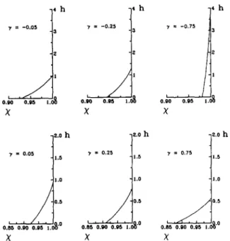
Fig. 1. Variation of basic state liquid mass fraction in the vertical direction of the mushy layer for various 9'.
0 = - 1 , (15a)
[p(u- ek).n]
= 0 , (15b)where Eq. (15b) accounts for the conservation of mass at the interface.
The above mathematical formulation differs from that of previous studies [5,10] by several respects. First, in Eq. (8) we consider the solute diffusion in the mush, which is ignored by Worster but can be impor- tant when • is not small. Secondly, at the melt/mush interface, we consider the Beavers-Joseph boundary condition for the tangential velocity along the inter- face, rather than use the no-slip condition [5,10]. Thirdly, the deviatoric stress is considered in the con- dition of the continuity of normal stress (Eq. (14g) ). These two interfacial dynamical conditions are influ- ential to the dynamical coupling between the convec- tion in the fluid and the mushy layers. A detailed dis- cussion of the comparison between these two mathe- matical models is provided in Section 5.1.
3. Basic state solution
Z, which is presented in the following. In the mushy layer, according to Eqs. (7) and (14b), the velocity of the interstitial fluid is
wb(z) = --YXb(Z), (16)
where the index b accounts for the basic state and w is the vertical velocity, Since at the melt/mush interface X = 1, the vertical velocity in the melt is accordingly
wb = - y , (17)
which is in accordance with the boundary condition Eq. (13c). The basic state temperature and concentra- tion in the fluid layer can be obtained from Eqs. (2) and (3), respectively,
Ob = 0c~ q- ( 0 i -- Ooo) e - ( l + y ) ( z - h ) ,
O b = 0i e -[(l+~')/el(z-h),
(18) (19) where the interfacial temperature is given by
0i = - ~ 8 o o . (20)
The equations and associated boundary conditions of Section 2 admit a steady solution as a function of
In the mushy layer, the relation 0 = ® applies. The liquid mass fraction of the mush Xb is governed by
EC. Lee, E Chen/Journal of Crystal Growth 154 (1995) 351-363 355 h h lO 8 6 4 2 0 10 8 6 4 2 0 10 10 8 (a 7 = - 0 . 7 5 i - - 0 . 5 0 0 . 5
(b)
I
T : 0.25(c)
6 4 2 0(o)
I
6 4 2 0 - 0 . 5 0 0.5 T = 0 . 2 5 ]]
- 0 . 5 0 0.5 T = 0.75 - 0 . 5 0 0.5Ob
10 8 6 4 2 0 [0 8 6 2 0 10 0 6 4 2 0 10 ( e ) - 0 . 5 0(f)
i 7 = 0.25 1'
~
"
I
- t - 0 . 5 0(g)
f
- 0 . 5(h)
[ I 7 = 8 0 7 5 6 4 2 o . . . - - 0 . 5 0@b
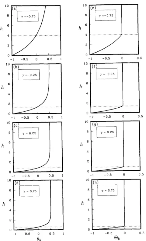
0.5 0.5 0.5 0.5Fig. 2. Basic state temperature and concentration distribution in the vertical direction for various % ( a ) - ( d ) : basic state temperature; ( e ) - (h): basic state concentration.
356 Table l
Physical properties and corresponding dimensionless parameters of 26 wt% NH4C1 solution
YC. Lee, E Chen/Journal of Crystal Growth 154 (1995) 351-363
A 0.65 C 12.3 C E 19.7 % c 3249. J / k g ° C ,T" 3.20 7-/ 3.5 x 10⁶ /~ 3.14× 10⁵ J/kg TE --15.4 °C or* 3.832x 10 - 4 ° C - I f t . 2.82x 10⁻³ % - 1 F 4.75 ° C / % y -0.31 e 0.013 0 ~ 0.5 Ktl 1.336 x 10 - 3 cm 2/s tr 10. - C Xb = (1 + y) (0b -- C) + e0~ + TC' (21) which can be deduced from Eq. (18), and the basic state temperature is governed by
O~' + ( l +YXb)O~-- f ' [ p b ( 1 - - X b ) ] ' = O , (22) which is derived from Eq. (9). Eqs. (21) and (22) and associated boundary conditions are solved with a shooting technique, in which the interface position h is also solved implicitly.
In this study, we focus on the volume change effect on the convective stability of a 26 wt % NH4CI solu- tion, whose physical properties are listed in Table 1. Using these data, the basic state solutions for various 3/are obtained as follows. Fig. 1 shows the distribu- tion of X in the vertical direction and the correspond- ing mushy layer height h. For y < 0 (Figs. l a - c ) , an upward flow is induced, both X and h increases as y decreases. This is due to the fact that the upward flow convectively carries cold and less concentrated fluid from below, enhancing the mushy-layer growth while decreasing the solid mass fraction in the mush. On the other hand, as 3 / > 0 (Figs. l d - f ) , a downward flow is induced and both X and h decrease with increasing y. This is because the downward flow brings warmer and more concentrated fluid from the bulk fluid into the mush, suppressing the mushy-layer growth while increasing the solid mass fraction of the mush. Fig. 2 illustrates the basic state temperature and concentra-
tion for various y. It is seen that increasing y enhances both the temperature and concentration gradients in the mush and the temperature gradient in the melt as well. The increase of the two gradients in the mush is due to the decrease of the mushy-layer depth. The in- crease of the temperature gradient in the melt is also due to the reduction of the thermal boundary-layer thickness.
4. Small disturbance equations and method of solution
We linearize the equations of Section 2 by intro- ducing small disturbances to the basic state quantities of Section 3 and substituting their combination into the original equations. After obtaining the linearized equations by neglecting higher order terms and ap- pling the normal modes proportional to e °'t+iax, the small disturbance equations are as follows. In the fluid layer, we have ( D 2 - a 2 ) W = l'~, (23) 0 2 + (l + y ) D - t o - - a 2 l'~ ] o r = a27-lRm[AO - ( 1 + A ) ® ] , (24) [ O 2 +
(1
+ 7)D - t o - o r 2] O = O~W, (25) leD 2 + ( 1 + y ) D - w - e a 2] 19 = O~W. (26) In these equations, the notations W, 0, ® now rep- resent small disturbance quantities. In addition, both and D represent the vertical derivative d / d z , a is the horizontal wave number, to is the normal mode frequency, II is the disturbance vorticity, ~ = H2/II,A = F a * / f l is the buoyancy ratio between the buoy- ancy due to concentration to that due to temperature,
RT = AT-[Rm, and RC = (1 + A)7-~Rm.
Similarly, in the mushy layer we have
E X b ( 1 + ' y X b ) D 2 0 + [E0~ + (1 + y ) ( 0 b -- C ) ] D x
= [ - 6 X ~ - (1 + 3/)(1 + T X b ) X b ] D O
YC. Lee, E Chen/Journal of Crystal Growth 154 (1995) 351-363
+ -e O;'--2yX'bO ;+ - 1 7 ~ b J
OW=O,
(
+ ( 0 b - - C ) ( l +'y) o9+ 1 ~ - ~ b , ] a t z
=hare
- 1)0~]X +(I
+ YXb)0~W, (27)+(y2Xb
J
(1 +yXb)2D2O +.,T'(1 + y ) 2 D X
= - ( 1 +'yXb)3D0 --{ -- (1 + YXb)2(a 2 +o9)0
(
2 x; )
+ ~ - ( l + y ) 2w+ 17-~-~D/X
+( 1
+TXb)20~W,
(28)DZw + TD2x
Y q'-'Y + ~'Xbl
I
~'~-~,¥b__ ~,2j
W,y2
+a2 RmI] ( Xb ) O
(1 + TXb) 2 X [ ( m 2 ~ l _ + Y Xb) Xb(
1 + YXb) Xb' L II' , I ] + ~ - X b ( w + YXb) ( 1 + YXb) X- (29) .IIn above equations, the disturbance density has been replaced by the disturbance mass fraction by the rela- tion
y(]
+ y )
p(z) =-(1
+ YXb(Z)) 2X(z)' (30)where now p and X are the small disturbance quanti- ties. This relation is obtained from the Taylor expan- sion ofEq. (12) with respect to the basic state.
The boundary conditions at z --' cx~ are
0 = 0 , (31a) O = 0 , (31b) 357 (31c) (31d) 0 = O, (32a)
D® - DO= (I + y) (~-e-~) O~,
(32b)[W] = 0, (32c)
[01 =
O,
(32d)
:Fo;
[DO]
= - ( I + y)C_---~n,
(32e)
g = - g ~ n , (32f)
and at z = 0 are
0 = 0, (33a)
W = -YX, (33b)
where r/is the small perturbation of the interface po- sition. At the melt/mush interface the continuity of normal stress is
[
D W -
YX~ W+yDx
Y(o)+yX~) ]
l + y l + y X h-
1-1(1) [ 1 + y
- 7-I LDII -t- O" (l'~ + a2W)
° ) O W - 2et2DW/ ,
(34)
o r J h +
in which the deviatoric stress is considered. The Beavers-Joseph boundary condition is given as
D2WIh+ = A v/--~ [DWIh+ __y2X'
+ ~ b y x -- yD X
+ YX'b W - DWIh- +
l + y ( l + y ) wX (35)Y
]
The eigenvalue problem is composed of Eqs (23) (29) and Eqs ( 3 1 ) - ( 3 5 ) and 14 boundary c o n d i tions, in which Eq. (32b) is used to solve the dis- turbance interface position r / W e solve this complex eigenvalue problem with a shooting method The i n tegration is implemented in a truncated domain [ 19],
in which the boundary conditions at z --+ oo are im- posed at a finite distance z = 20, which is sufficiently large so that the results are independent of the value
358 Y.C. Lee, E Chen/Journal of Crystal Growth 154 (1995) 351-363 15 12 9 6 (a) (b) 30 . - - - . - - - , - - , . , , . . . _ . . ~ o ~ • . . . • • • • ~ 20 ~,c ! : I I 0.45 0.60 10 . . o . . . . o . . . . o . . .
/
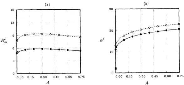
o.,, ~ I 0.45 0.60 0 i 0 0.00 0.15 0.30 0.75 0.00 0.15 0.30 0.75 A AFig. 3. C o m p a r i s o n b e t w e e n the results obtained from Worster's ( 1 9 9 2 ) model ( d a s h ) and the present model ( s o l i d ) for an alloy o f .T = C = 000 = I, o- = 10, ~ = 0.025, ~ = 105, and rl = 1. The curves show the variations of/~m and a¢ with A, the b u o y a n c y ratio.
of z. The two-layer configuration is converted into a single layer by the superposition method developed by Keller [20], in which an orthonormalization pro- cess is applied to avoid the loss of linear indepen- dence of integration. This method was later improved and called parallel shooting by Davey [21] who de- veloped the automatic orthonormalization process. An iteration procedure developed by Powell [22] is em- ployed to seek the convergence of the eigenvalues Rm and ~oi.
The present eigenvalue problem has some inherent difficulties. For example, the physical domain consists of two different layers, the equations of different lay- ers have different characteristic scales, and so on. The difficulties are especially prevalent in the high a do- main and on the Hopf bifurcation branch as well. To obtain a point on the monotonic branch curve for a > 30, for instance, about 250 CPU seconds of CRAY Y M P / E L is essential. For a point on the Hopf bifur- cation branch, more than 600 CPU seconds are re- quired. More severely, the initial guess of o) i needs to be within 20% of the final solution.
5. Results and discussion
5.1. Assessment of mathematical model
The present mathematical formulation can be em- ployed to investigate the problem of Worster [5] when
y = 0 (so that the liquid mass fraction is equal to the liquid volume fraction), the solute diffusion in Eq, ( 8 ) is neglected, the Beavers-Joseph condition Eq. (14h) is replaced by the no-slip condition, and the devia- toric term in Eq. (14g) is dropped. The computer code written according to this reduced model is employed to run the case considered in Worster, i.e., .T = C = 0oo = 1, o- = 10, 6 = 0.025, 7-/ = 10 s, A = 0, and a uniform permeability I I ( x ) = 1. The neutral curve we obtain, a monotonic one in which the mushy-layer mode is more unstable than the boundary-layer mode, is exactly the same as that of Fig. 3 of Worster. We then compute the critical Rayleigh number /~m and critical wave number a c for non-zero A and the re- sults are illustrated with the dashed curves in Fig. 3. For the physical significance of A, the reader is re- ferred to Chen, Lu and Yang [ 10], in which a detailed discussion is provided.
We then consider the present mathematical formula- tion for the same case and the results are shown in the same figure with solid curve. Note that for both curves of Fig. 3 the values of/~m and ot c are corresponding to the boundary-layer mode convection except the point of A = 0 where the mushy-layer mode convection pre- vails. Results show that the RCm of present study is in general 30% lower than that of Worster [5]. Since the value of E of the present case is small, the influ- ence of the solute diffusion in the mush is negligible.
YC. Lee, E Chen/Journal of Crystal Growth 154 (1995) 351-363
359
160 140 120 I00 R ~ 80 60 40 20 0 y i 0 10 2 0 3 0 O( i i il
"7--
0.01(a)
40 50 20 80 15 60 I0 ~ R~. 40 5 20 0 60 i I i 0 10 20 (3( ~ b~7
: - 0 . 1(d)
i 30 tO 8 6 4 2 0 4O 160 140 120 I 0 0 Rm BO 60 40 20 0i
/ I i7=0.5
i 0 I0 20 30 40 (X b 2 0 15 10 CO 5(b)
~ 0 50 60 80 6O ~m 40 20 0 0 lO b i 3(e)
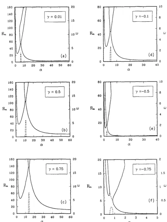
I i 0 20 30 40 (3( £0 8 6 co 160 , j , , j 20 20 2 140 ~ -)' = 0 . 7 5 I~0 15 15 ~ - 1.5 tO0 R,~ Bo toG; P,~ ~o t c,.; 60 40 5 5 0.5 20 0 0 0 0 0 i0 20 30 40 50 60 0 I 2 3 4Fig. 4. The neutral curve topology for various 7; solid: monotonic mode; dot: oscillatory mode; dash: oscillation frequency. Note that the curve of oscillatory mode lies between the two curves of monotonic mode for all the sub-figures.
360 Y.C. Lee, E Chen/Journal of Crystal Growth 154 (1995) 351-363
The deviatoric stress in Eq. (14g) and Beavers-Joseph condition of Eq. (14h), nevertheless, are responsible for the difference shown in Fig. 3. Because, firstly, the normal gradient of the vertical disturbance veloc- ity at the interface is not at all small if the boundary- layer mode convection predominates, which is the case when A > 0 (see Fig. 1 of Chen, Lu and Yang [ 10] ); secondly, the Beavers-Joseph condition allows a slip of tangential velocity along the interface, which com- pared to the no-slip condition [5,10] is less restrictive to the flow and thus leads to a more unstable situation. In addition to the stability criteria, these two bound- ary conditions can also be influential on the dynamic coupling between the convection in the fluid and the mushy layers, which is especially important to the os- cillatory mode on the Hopf bifurcation branch since in this mode the convection cells in the two layers are viscously coupled through the interface. This shall be discussed in the next section.
(a)
8o~.
leo
' ° F "
1 '°
N . % ' - ; . , ' - ~ , , , ' - ; . 2 " o.o ' o.'2 ' o.~ 'o.'6 "o.?
7
16 (b) 16
5.2. Stability of NH4Cl solution cooling from below
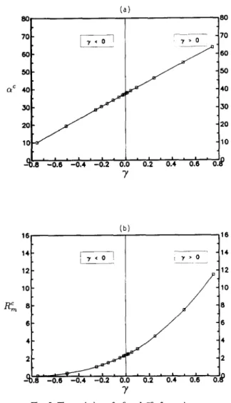
In this section, a 26 wt % NH4CI solution is con- sidered, whose physical properties are listed in Ta- ble 1. Since no experimental data are directly avail- able to identify the permeability function H (X) of the mush of NHaCI solution, we therefore consider for simplicity a non-uniform permeability II = X 3 to ac- count for the mushy-layer morphology; this is simi- lar to Fowler [ 13] who assumed H = X 2. Note that the use of present permeability model may well simu- late the dendritic matrix of the mushy zone of experi- ment, especially on the melt/mush interface on which X = 1. The effect on the stability due to ~ ranging from 0.75 to - 0 . 7 5 is considered and ~, ~ - 0 . 3 for 26 wt% NHaC1 solution [9]. In Fig. 4, several se- lected neutral curves of various ~ are illustrated. It is seen, by and large, that the neutral curve consists of two separated monotonic branches and a Hopf bifur- cation branch sitting in between, the boundary-layer mode (high a mode) is invariably more unstable than the mushy-layer mode (low a mode), and the os- cillatory mode never predominates. When )' is less than - 0 . 7 5 (Fig. 4f) the mushy-layer mode virtually vanishes, leaving the boundary-layer mode predomi- nates. We summarize both a c and Rein of various 3~ in Fig. 5, showing that the basic state becomes more stable as T increases, and that the critical wave num-
14 ~ 14. ; "y > 0 1 2 1 2 1 0 1 0 R~ 8 B 6 $ 4 4
_c ~ ' - o . 6 -o.4 -o.2 o.o "o.? "o.4 'o.6
'o.#
Y
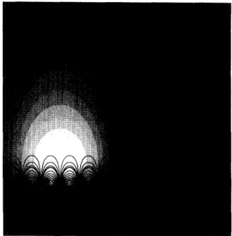
Fig. 5. The variation of a c and RCm for various % bet increases linearly with ~ as well. Fig. 6 shows a typical onset streamline pattern of the two instability modes of ~/= - 0 . 1 (see Fig. 4d for the correspond- ing neutral curve). In this figure, the most unstable boundary-layer mode is demonstrated with solid lines and the mushy-layer mode is shown with shadow. The horizontal wave length is normalized with respect to the mushy-layer thickness, on which all dimension are scaled. One can see that the boundary-layer mode con- vection is largely confined to the small boundary-layer above the melt/mush interface while the mushy-layer mode circulates between the fluid and mushy layers although largely confined to the latter. In the present case, the basic flow induced by the volume change does not significantly influence the onset flow.
Y.C. Lee, E Chen/Journal of Crystal Growth 154 (1995) 351-363 361
Fig. 6. The critical streamline patterns of the boundary-layer mode (solid) and the mushy-layer mode (shadow) of "y = - 0 . 1 The cells at the left and the right are circulating in opposite sense.
Fig. 7. The critical streamline patterns of the boundary-layer mode (solid) and the mush-layer mode (shadow) of ~, = - 0 . 7 5 . The cells at the left and the right are circulating in opposite sense.
The physical explanation to the above results are proposed in the following. For 7 > 0, a downward flow is induced. The boundary-layer mode becomes more stable as ~, increases since both the thermal and solutal boundary layers are reduced in thickness, lead- ing to a more stable situation. The mushy-layer mode also becomes more stable as "y increases. This is due to the fact that the mushy-layer mode is largely confined to the mushy layer in which the porosity decreases as 3~ increases, resulting in a more stable situation. The critical wave number a c, inversely proportional to the critical wavelength, of both modes increases with 9~ because both the boundary layer and the mushy layer, to which the instability modes are largely confined, are reduced in thickness as "y increases (see Figs. 1 and 2). The linear relation between a e and ~ is due to the fact that the compositional boundary-layer thick- ness decreases approximately linearly with increasing )', which we determine from the numerical results. For "y < 0, an upward flow is induced. For the boundary- layer mode, as ), decreases, a stronger upward flow increases the thermal boundary layer thickness, lead- ing to a decrease of the stabilizing thermal gradient and thus a more unstable state. The mushy-layer mode also becomes more unstable as 3~ decreases since the
porosity increases.
To gain more physical insights into the 9' effect, we present another onset streamline pattern of 3' = - 0 . 7 5 in Fig. 7. Note that in reality the mushy-layer thickness of Fig. 7 shall be larger than that of Fig. 6, which is nevertheless not reflected in these two figures. This is due to the difficulty that if the two figures are scaled with, for instance, the mushy-layer thickness of ~ = - 0 . 1 , the size of Fig. 7 shall be much larger than the present one; and vice versa when scaled with
(a) (b) (c)
Ii' i' i ii':iii::l ;i:i i' ii',ill
Fig. 8. The onset streamline patterns of oscillatory mode of = 0.75. (a) a = 13.24; (b) a = 13.84; (c) vt = 14.42. Note that the oscillating frequency is largest in case (b) since the con- vection in the mush is the weakest in the three cases considered.
362 YC. Lee, E Chen/Journal of Crystal Growth 154 (1995) 351-363
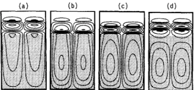
(a) (b) (c) (d)
Fig. 9. The onset streamline patterns of oscillatory mode of T = 0.75 and a = 13.84. (a) t = 0; (b) t = 7r/4; (c) t = Ir/2; (d) t = 3~'/4.
6. Conclusion
We have proposed a different mathematical model to investigate the volume change effect on the salt- finger instability of directionally solidifying NH4CI solution. It is found that the induced basic flow changes both the morphology and the depth of the mush, which in turn influences the stability charac- teristics of the onset of salt-finger convection. More precisely, for ~ > 0, a downward flow is induced; both the boundary-layer and the mushy-layer modes become more stable as ~, increases; for -y < 0, an upward flow is induced, both modes become less sta- ble as 3' decreases. For ~ < - 0 . 7 5 , the mushy-layer mode virtually vanishes, implying that the plume con- vection, a direct result of the subcritical mushy-layer mode convection, may be more difficult to occur. ~, = - 0 . 7 5 . It is seen from Fig. 7 that, for ~ = - 0 . 7 5 ,
the induced large upward flow not only enhances the height of the boundary-layer mode cell, but brings most of the mushy-layer mode convection upward to the fluid layer. This enlarged cell eventually vanishes as 7 decreases further. It is also of interest to examine the onset streamline pattern of the Hopf bifurcation branch. Fig. 8 illustrates three streamline patterns of the oscillatory branch of ~, = 0.75, which, after exam- ining several other ~, is found to be representative for most of the cases considered. It is seen that the oscilla- tory mode consists of several convection cells, coupled viscously to each other (Fig. 8a). In a configuration consisting of two immersible superposed fluid layers heated from below, Rasenat, Busse and Rehberg [23] indicated that the two cells occurring in the two sep- arated layers are in some senses viscously coupled through the interface, leading to the oscillation of con- vection. For the present problem, the viscous coupling occurs largely at the melt/mush interface, at which the cells in the mushy and boundary layers are influ- enced by each other through viscous forces. As the oscillation frequency increases (Fig. 8b), the cell in the mushy layer becomes weaker while the cells in the boundary layer are sustained. Then in Fig. 8c, the con- vective strength in the mushy layer recovers, accom- panying a lower oscillation frequency. Fig. 9 shows a cycle of the oscillation of the mode of Fig. 8b, illus- trating that during the cycle of oscillation the cells in both layers interchange convective momentum.
Acknowledgement
The financial support for this work from Nation Science Council through Grant No NSC 83-0401-E- 002-005 is gratefully acknowledged.
References
[1] A.K. Sample and A. Hellawell, Met. Trans. 15 A (1984) 2163.
[2] S. Tait and C. Jaupart, Nature 338 (1989) 571. [31 C.E Chen and E Chen, J. Fluid Mech. (1991) 227, 567. [4] D.G. Neilson and EE Incropera, Intern. J. Heat Mass
Transfer 34 (1991) 1717.
15] M.G. Worster, J. Fluid Mech. 237 (1992) 649.
[6] G. Amberg and G.M. Homsy, J. Fluid Mech. 252 (1993) 79. [71 C.S. Magirl and EP. Incropera, J. Heat Transfer ASME
Trans. C !15 (1993) 1036.
[ 8] M.H. McCay, T.D. McCay and J.A. Hopkins, Met. Trans. B 24B (1993) 669,
[9] A. Hellawell, J.R. Sarazin and R.S. Steube, Phil. Trans. Royal Soc. (London) A 345 (1993) 507.
[ 10] E Chen, J.W. Lu and T.L. Yang, J. Fluid Mech. 276 (1994) 163.
[ 11 ] E Nandapurkar, D.R. Poirier, J.C. Heinrich and S. Felicelli, Met. Trans. B 20B (1989) 711.
[12] S.H. Davis, J. Fluid Mech. 212 (1990) 241. [13] A.C. Fowler, IMA J. Appl. Math. 35 (1985) 159. [141 A.O.P. Chiareli and M.G. Worster, J. Crystal Growth 125
(1992) 487.
[15] G.B. McFadden and S.R. Coriell, Phys. Fluids 30 (1987) 659.
YC. Lee, E Chen/Journal of Crystal Growth 154 (1995) 351-363 363 [17[ G.S. Beavers and D.D. Joseph, J. Fluid Mech. 30 (1967)
197.
[18] E Chen, J. Appl. Phys. 71 (1992) 5222.
[ 19] S.R. Coriell, M.R. Cordes, W.J. Boettinger and R.E Sekerka, J. Crystal Growth 49 (1980) 13.
[201 H.B. Keller, Regional Conference Series in Applied Math., SIAM, Philadelphia, PA (1976).
[21] A. Davey, J. Comp. Phys. 51 (1983) 343.
[22] M.J.D. Powell, Numerical Methods for Nonlinear Algebraic Equations, Ed. EH. Rabinowitz (Gordon and Breach, New York, 1970).
[23] S. Rasenat, EH. Busse and 1. Rehberg, J. Fluid Mech. 199 (1989) 519.