VORAL: A System for Voice Over IP Routing in Application Layer
CHUNGY
IH-Y IH WANGCHING-CHI
HSUY E N ”
HUANG
Department
of
Computer
Department
of
Computer
PreCache Inc.
Science and Information
National Taiwan University,
Science and Information
National Taiwan University,
555
Madison Ave. loth Floor
Engineering
Engineering
New York, NY 10022
Taipei, Taiwan
Taipei, Taiwan
Abstract
There are three key metrics (end-co-ed delay, packet loss rate and delay variation) for determining the quality of Voice over
IP
(VoIP). The impact of delay variation can be reduced by de-jitter buffering at a receiver side. The impairment caused by the packet delay and loss can be reduced by routing the traJic through an Internet path with a better quality. However, the current Internet infrastructure has not yet supported a complete QoSrouting. Consequently, the quality of VoIP today, especially over U wide-area network for international
calls, is ofren unbearable. In this paper, we present c1 system VOR4L (Voice Over
IP
Routing in Applicution Layer) that can signiJcantly improve the QoS of VoIP by routing the voice packets in the upplication layer through various relay servers in the Internet. The routing techniques use R-jiactor, a parameter determined by packet loss rate and packet delay, to select U path with the best VoIP quality for a call. The paths of incoming traflc a d the outgoing traffic can be d@erent and be dynamically changed during a cull. The usefulness of the VORAL system is further validuted by an experimental VoIP service between US and Taiwan.1.
Introduction
In VoIP, voice generated by a sender is encoded in small IP packets, which are then transmitted to a receiver over the Internet. At the receiver’s side, the voice packets
are assembled and decoded to reproduce the voice. Usually, VoIP applications support many kinds of codecs, such as G.711 (Nkbps), G.728 (16kbps), G.729a (8kpbs) and G.723.1 (5.3/6.4kbps), to meet various quality requirements. Using the Internet today, there are three
key metrics that influence the quality of VolP: packet delay, packet loss rate and delay variation between endpoints [ 11 [7].
To make the quality of VoIP acceptable to users, ITU-T recommended that one-way packet delay be less than 150 milliseconds to ensure the quality of a real-time interaction [6]. There are three major components that contribute to the one-way fixed packet delay. The first component is the propagation delay, which is determined by the speed of light traveling from one end to the other. The second component is the time to serialize packets and transfer them into a network. For example, it takes 7.25 ms to push a voice packet of 116 bytes into a DUAL- ISDN link (128kbps). The last component is the time for encoding and decoding the voice data, In addition to the fixed delay, there are other factors that contribute to the one-way packet delay, such as network congestion and performance of routers.
In order to achieve a real-time response, the Real- time Transport Protocol (RTP) and Control Protocol (RTCP) support the transfer of real-time media over IP. However, RTP does not support any mechanism for ensuring an on-time delivery of VoIP packets or recovering lost packets. Besides, RTP does not resolve the quality of service (QoS) issues related to the availability of network bandwidth for a specific application.
Currently, the Intemet can only support the best- effort delivery of IP packets, it is very difficult to guarantee any QoS property of a VoIP application in the transport or network layers. To ensure a good quality of voice over the Internet today, several techniques in the application laycr have been proposed to reduce the impairment caused by the three key factors. For example, a smoothing play-out buffer can be used at the receiver’s
side to remove the jitter caused by the delay variation [9]. Techniques using Forward Error Correction (FEC) can be applied to compensate errors due to packet loss in codec transformation [ 141 and packet delivery [lo].
However, the increasing popularity of the use of
Internet often generates more network congestion, which in turn causes a longer packet delay and a higher packet loss rate in transmission. To solve the problem, network- layer solutions such as Integrated Services (IntServ) and Differentiated services (DiffServ) [4] have been proposed to guarantee a QoS delivery of packets over the Intemet by classifying the Internet traffic into different categories and routing the packets based on the QoS requirement of each category. The network-layer solutions require all routers in the Internet to have the QoS routing capability. It is still many years away for the QoS network routing to become reality. As a result, we cannot rely on the network layer solutions today to improve the VoIP quality [8].
A research results shows that, for about 30 to 80
percentages of network routing paths, there exists at least one alternative path, which may have a significantly superior quality in terms of round-trip delay, packet loss
rate and bandwidth than the default path [13]. To experiment the idea of alternative path for VoIP traffic, we designed and implemented the VORAL system, which consists of relay servers, proxy servers and VoIP gateways. The relay servers dynamically choose the path for each VoIP call with the best quality of voice; i.e., the shortest delay and the smallest loss rate. All relay servers
in the system form a VoIP Network Clique (VNC). Each relay server maintains an application-layer routing table(or path table), which is the table of the best routing paths between itself and all the other relay servers in a VORAL. In addition to doing the optimal VoIP routing,
the VORAL architecture also provides useful management information such as packet loss rate, packet delay, the quality of voice rating and path information. To validate the usefulness of our approach, we construct a VoIP service from US to Taiwan using the VORAL system. Experiment results show that the application- layer routing using the VORAL system can significantly improve the quality of the international VoIP calls.
The paper is organized as follows. The overview of
VORAL is introduced in section 2. In section 3, we discuss the quality of VoIP and the measurement of the quality of voice in VORAL. Section 4 describes the components in a relay server of VORAL. An experimental VORAL service and its results are described in section 5 . Section 6 concludes the paper and outlines
the future work.
2. System Overview
A very common policy used by large network service providers (NSF’s) or Internet service providers (ISPs) is the “early-exit’’ routing [ 3 ] . In this routing scheme, a service provider network routes the packets that come
from another service provider to the nearest hop as
quickly as possible, disazgarding whether there exists a better path to the destination node or not. Between service providers, Border Gateway Protocol (BGP) is often used to route network traffic [12]. BGP does not necessarily select routes by minimixing packet loss rate or packet delay.
9
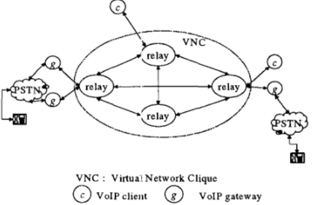
VNC : Virtual Network Clique
6)
VoIP client V ~ I P gateway Figure 1 . The system architecture of VORAL As more than 30% of Internet Service Providers aremulti-homing, there are many potentially better paths between any two hosts over the Internet at any time than the default path, determined by the underneath network routers. However, the impacts of the alternative Internet paths and the application-layer routing on the VoIP quality have not been studied before. To understand and take advantage of the application-layer routing using alternative paths, we use several relay servers to constitute a Virtual Network Clique, namely VNC.
As shown in Figure 1, the system architecture of
VORAL is constructed by a VNC (a clique of relay servers) and several VoIP endpoints. Obviously, there are many paths between any. two relay servers in VNC. In order to route the VoIP traffic along the path with the best quality in VNC without modifying any VoIP standard, a VORAL relay server has to route the voice traffic in application layer. Using this relay technique, the flow of the VoIP traffic is not limited to the default path determined by the network routers between a sender and a receiver. Instead, if there is an altemative path with a
better quality in VNC, the VoIP traffic is forwarded to the endpoint through the intmnediate relay servers along the path in VORAL. In order to achieve the best possible paths, we distribute the VoIP relay servers over the Internet on hosts of various ISPs or NSPs. Intuitively, one
VoIP endpoint can register to a VoIP relay server with the lowest delay and lowest loss rate to benefit from the best quality of link between them. On the other hand, to facilitate the path selection, we also maintain a path table that allows each relay server to look up the link information of neighboring relay servers. The measurement of the quality metrics of different paths in VORAL is discussed in next section.
For a VoIP endpoint to join V O W environment, a proxy server which is a relay server in VNC manipulates the call/media signaling and voice traffic for VoIP endpoints to deliver these packets in VORAL. In addition to routing packets, the proxy server also handles network authentication and firewall issues. Using the proxy server, any VolP application can join VORAL to take advantage of the application-layer routing without changing the application program. The activities of proxyhelay sewer are discussed in detail in Section 4.
3.
Measurement
of
the VoIP Quality
Since the best path from a sender to a receiver could be different from the best path from the receiver back to the sender, we need a mechanism that can measure the one-way packet loss rate and delay. The ping command only provides the information about network round-uip delay and round-trip packet loss rate between two hosts [li]. Besides, due to the threat of a denial of service (DOS) attack, some routers may drop the ICMP messages used by the ping command. Therefore. in VORAL, we implement an UDP-based measurement tool, namely r a p i n g , to measure the round-trip delay and one-way packet loss rate for all paths between each pair of relay servers.
The tool, myping, requires a sender and a receiver to run on two different relay servers in the VNC of VORAL. For each path between a sender and
a
receiver,one tnyping session is created and the sender periodically
invokes an echo request UDP packet to the receiver through the intermediate relay servers along the path. Each time, the sender increments its local ping-counter (LPC) associated with the session by one. Each request message contains the session sequence number, the current local time and path information (PI). The session sequence nuniber is used to ensure that the sender and the receiver are synchronized in the same session. The path information consists of the order of the relay servers raveling from the sender to the receiver. Upon receiving a request message a relay server checks if it is the target receiver. If not, the messaze will be forwarded to the next relay server indicated in the PI field of the request message without any modification of it. Once the target receiver receives an echo request from a client. the received ping counter (RPC) associated with the session
number will be incremented by one. Next, the receiver attaches the associated W C to the reply message and sends it back to the sender along the path in the reverse order. When the sender receives the reply message, the packet loss rate from the source node to the destination node traveling through a specific path can be easily calculated by LPC and RPC. Using this mechanism, we can measure the one-way loss rate and round-trip delay for all the paths between any pair of relay servers in
VORAL.
R-factor
In ITU-T G.113 Recommendation, the R-factor deter-mines the Mean Opinion Score (MOS) [ 5 ] , which is a common measure of voice quality. For telecommunica- tion, the R-factor is defined in terms of several parameters associated with a voice channel across a mixed Switched Circuit Network (SCN) and a Packet Switched Network (PSN). Robert G. Cole, et al. proposed
a
formula with loss rate and one-way delay to calculate the value of R-factor for VoIP requirements [2].R = 94.2
-
Dc-
I,D, 0.024 d
+
0.11 H(d-
177.3) (d-
177.3) H(x) = 0 if x < 0, else H(x) = 1 for x >= 0where D, is merely a function of the mouth-to-ear, one- way delay, d is the one-way delay (in milliseconds), e is the one-way loss rate and H(x) is a step function. For I, , there is one formula for each codec.
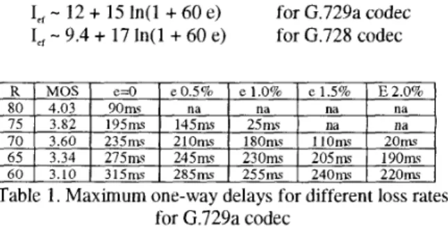
I,,
-
12+
15 In(]+
60 e) I,,-
9.4+
17 In(1+
60 e)for G.729a codec for G.728 codec
Table 1 . Maximum one-way delays for different loss rates
for G.729a codec
According to the formula of R-factor, we can easily construct Table 1 for the maximum one-way delays in various loss rates for G.729a codec. For example, if one wish to maintain
a
link with R-factor larger than 70, the one-way delay between endpoints can not be larger than 235 ms if the loss rate is 0, or is decreasing as increasing loss rate. In comparison with conventional VoIP, for any two nodes ci and 0, if you want to maintain a link with the R-factor value of the default path from node a to node b is 65 with 2.5% loss rate and 145 ms one-way delay, the R-factor value can be up to 70 by the application-layerrouting if there exists an altemative path with 1.0 % loss rate and 180 ms one-way delay from node U to node b through some intermediate nodes. For VoIP, if the R- factor is over 60, the sound quality is considered fair.
4.
VoIP Relay Server
In order to reroute the media traffic in application layer, there are five components in a VORAL relay server. CallCtlRelay(C) is used to relay the call control signal. MediaCtlRelay(M) provides the relay service for media control channel. UDPRelay(R) provides the media packets (RTPRTCP packets over UDP) forwarding in the VNC of VORAL. Call-Table(T) keeps the information of
call connections and endpoints. Path-Table(P) provides the quality metrics of paths between itself and any other relay servers in VNC.
There are two tables in the component of Call- Table(T). One is the connection table. This table stores the information of the current connections including the IP addresses, media control ports, and port numbers for RTPRTCP of callers and callees. The other is the proxy- endpoint table. The proxy-endpoint table helps the proxy of caller to find out the proxy of the callee in VNC.
In VORAL, each relay server maintains its own routing table called Path-Table(P). The Path-Table(P) can be constructed using the R-factor values. Each entry of the Path Table in a relay server represents the path with the largest R-factor from the relay server itself to another relay server in VNC. The table is updated periodically to reflect the changes of current network status.
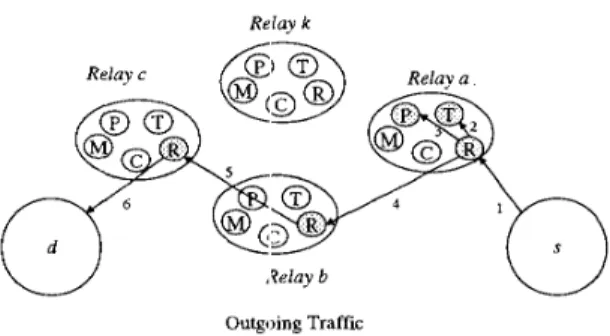
As an example to explain how the V O W relay server achieve the call routing, we assume that there is four relay nodes (a,b,c,k) in a VNC and two endpoints s,d as shown in Figure 2. Let’s further assume that the best path between node a and node c is a-b-c in the VNC. Let’s also assume that the proxy-endpoint table in each relay server has two entries of (node a, node s) and (node
c, node d, already. If there is a call from node s to node d, the sequences of actions of the CallCtlRelay, MediaCtlRelay and UDPRelay are described below:
The major function of CallCtlRelay(C) is to relay the call signaling along the path with the best quality between endpoints in VNC. CallCtlRelay(C) keeps the media control information into Call Table(T) and modifies the call signaling messages for redirecting the signaling traffic in VNC
.
Similar to CallCtlRelay, MediaCtlRelay is used to keep track of the media control information such
as
the UDP ports for media traffic and relay the media control messages along the retum path of the call signaling.After the call signaling and media control channels are established, the voice packets can be delivered in
VORAL with application-layer QoS routing. The proxy nodes of both endpoints have RTPRTCP port numbers of endpoints. As shown in Figure 2, the following is the details of voice traffic routing:
Relay k
Outgoing Traffic
Figure 2. Outgoing tiraffic from node s to node d For outgoing voice traffic, the step-by-step activities
of UDPRelay are:
1 . When a voice packet is transmitted from node s to
node a, the UDPRelay on node a first looks up the call information in its intemal cache table to check if there is the call information of the call. If so, go to step 4.
2. If not, UDPRelay on node ci looks up the connection table of the Call Table to acquire and cache the entire call information between nodt: s and node d.
3. the UDPRelay looks up the Path-Table(P) to obtain and cache the path with the best quality to the proxy node (i.e. node c) of the destination. The path information in
the intemal cache from node a to node c will be updated to maintain the best qua1ii.y of service by polling the Path- Table(P) periodically.
4. UDPRelay attaches the destination (or node cl) IP
address, RTP/RTCP port number and the path information to the pack:t. This encapsulated packet is forwarded to its successo~* node of the path (i.e. a-b-c.) 5 . Check if the node is the destination proxy of encapsulated packet. If not, the packet is forwarded to its
successor node of the path.
6. If it is the destination proxy for the encapsulated packet, UDPRelay removes the attachment and sends the original voice packet to the associated port number of the destination node from tht: information in the encapsulated packet.
Similarly, the incoming packets are delivered. Taking advantage of this routin!; mechanism, the path could be dynamically changed duiing a call and the incoming path and outgoing path can blz different in order to obtain the best quality of service.
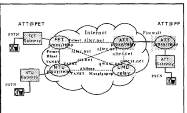
A T T @ FET
Figure 3. A VoIP service between US and Taiwan using VORAL
5.
Experiments and Results
As Figure 3 shows, we have built a VoIP service network based on the VNC framework. The network consists of four relay servers: ATT (AT&T Shannon Labs), UMD (University of Maryland), NTU (National Taiwan University) and FET (AT&T office in FarEasTone), located in New Jersey, U.S.A., Maryland, U.S.A., Taipei, Taiwan and PanChiao, Taiwan, respectively. The propagation delay (excluding the codec processing, serial-ization time, etc.) from US to Taiwan is around 77 ms. Packets from ATT to NTU pass through three ISPs-ALTER.net, A7T.net and TANET (Taiwan Academic NETwork). The ISP between ALTER.net and UMD is QWEST.net while the ISP between TANET and UMD's Maxgigapop is Abilene, an advanced backbone network within the Internet2 community. In this VNC, for a caller in AT&T calling a callee in NTU, there are five possible paths for the voice packets to travel through the VNC relay servers: ATT-NTU, ATT-ET-NTU, ATT-UMD-NTU, ATT-UMD-FET-NTU, and ATT-FET- UMD-NTU. We consider only the first four paths in each myping measurement session because the last path (ATT- FET-UMD-NTU) always has a very long propagation delay (221 ms, i.e. triples of the propagation between US and Taiwan) which makes it unacceptable at any time in our experiments. In a relay server, each rnyping session generates 300 ping messages per five minutes. Moreover, the Path-Table(P) on each relay server can be updated every five minutes to maintain the best qualities of the paths between itself and any other relay server in VNC.
The experiments are designed to measure the one-
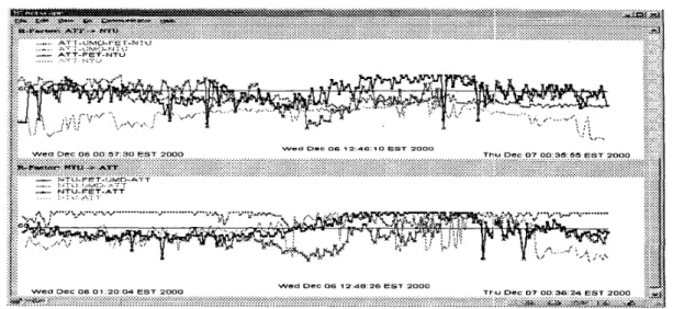
way delay and one-way packet loss rate to calculate the R-factor values for the paths between ATT and NTU and the paths between ATT and FET using the VORAL framework. An international VoIP call can be made between two endpoints in US and Taiwan using our VORAL system. Figure 4 shows the data measured by the
tool myping only from Dec. 6, 2000 00:30PM EST to Dec. 7 2000,00:30PM EST.
If the R-factor value is over 60, the quality of the VoIP is considered fair. As shown in Figure 4, for voice packets going from ATT to NTU the R-factor of the default routing path (ATT-NTU) is always lower than the fair value. Usually, there exists a path with the value of R-factor greater than 60 (i.e. the quality is acceptable) among these paths (An-FET-NTU, An-UMD-NTU and Am-UMD-FET-NTU) during the experiment. Obviously, we can achieve a better VoIP quality by routing the VoIP packets from ATT through FET or UMD to NTU, instead of routing the packets from ATT to the NTU directly. Moreover, the results show that using the V O W framework, the R-factor values can be improved from 35 to 70s in average for a call from ATT to NTU. As a result, the quality of voice is significantly improved. From the figure, we notice that the best path between ATT and NTU can be different at different time. This suggests that our VORAL application-layer routing mechanism, where the Path Table(P) is periodically updated after each myping session, can be very useful. The low R-factor of the default path ( A n - N T U ) is caused by the h i g h loss rate (about 30%) of the default path (ATT-NTU) which makes the VoIP quality using the default path unacceptable. The high packet loss rate from ATT to NTU could be due to the heavy usage of the TANET, the educational Internet service in Taiwan, and its bandwidth management policy. With the bandwidth control for the link, the variance of one-way delay and loss rate is not predictable.
6. Concluding Remarks and Future work
In this paper, we presented the VORAL application- layer routing techniques to achieve a better quality of voice over IP. To validate the usefulness of the frame- work, we built an experimental V O W service betweenUS and Taiwan in the public Internet. The results showed that VORAL can significantly improve the quality of voice by selecting the path with the best R-factor and delivering the voice packets along the path. Also, to make a VoIP phone call, the destination selection can help us to select the destination node with a better quality of voice automatically when there are more than two gateways residing on different network service providers. The results also showed that the path with the best quality for VoIP can change over time and we should route VoIP packets dynamically. Furthermore, for any two endpoints (e.g. a sender and a receiver), the best path from the sender to the receiver can be different from the best path from the receiver back to the sender. The V O W system takes into account all the factors to improve the VoIP quality between any two points.
. . . , , . . . . . .
wed D=C 06 - 2 4 8 . 2 6 EST 2 0 0 0
Figure 4. R-factors of diffes-t paths betweem ATT 2-d N-ru
Currently, we are working on the scalability and fault tolerance issues of the VORAL system. We are replicating relay servers and improving application-layer
QoS routing mechanism for scalability.
Acknowledgement
We would like to thank Herman Rao, Bob Hall and Chih-Mei Lin for many useful discussions on the VORAL project. We would also like to thank Chris Ramming, Adam Lee, Di-Fa Chang and Eric Lin for
helping us to install and maintain the relay servers in their networks.
References
Casetti, C.; Martin, J.C. D.; Meo, M. "A Framework for the Analysis of Adaptive Voice over IP," Proceedings of the IEEE Intemational Conference on Communications Cole, R. G.; Jo, M. and Deng, M. "VoIP Networking Requirements for Call Quality," to appear on AT&T Technical Memorandum, 2000.
Freedman, A. "Optimal External Route Selection: Tips and Techniques for ISPs," Tutorial at 14th North American Network Operators Group (NANOG) Meeting, November 1998.
tilti):~//www..:etl:~;~~ for more details.
ITU-T G.113, "Transmission Impairments," Transmission Systems and Media: General Characteristics of International Telephone Connections and International Telephone Circuits, February, 1996.
ITU-T G.114, "One-way Transmission Time," Transmis- sion Systems and Media: General Characteristics of (ICC2000), pp. 821-826, 2000.
International Telephone Connections and International Telephone Circuits, February, 1996.
Kostas, 1'. J.; Borella, M. S.; Sidhu I.; Schuster, G. M.; Grabiec, J. and Mahler M. "Real-Time Voice Over Packet-Switched Networks," IEEE Network January/F:ebruary, p p 18-27, 1998.
[8] Mishra, P. and Saran, H. "Capacity Management and Routing Policies for Voice over IP Traffic," IEEE Network MarcWApr il, pp. 20-27, 2000.
Moon, S. B.; Kuros:, J. and Towsley, D. "Packet Audio Playout Delay Adjustment: Performance Bounds and Algorithms," ACMISpringer Multimedia Systems, VOL. [lo] Padhye, C.;Christeiisen, K. J.;Moreno, W. "A New Adaptive FEC Loss Control Algorithm for Voice Over IP Applications," Proceeding of the IEEE IPCCC 2000, pp. 307-313, Feburary, ;!000.
[ 111 Paxson, V. "End-to-End Internet Packet Dynamics," IEEE/ACM Transaction on Networking, VOL. 7, NO. 3, pp. 277-2!92, June 15199.
[12] Rether, Y.;Li, T. "A Border Gateway Protocol 4 (BGP- 4)," RFC-1771, 1995.
[13] Savage, S; Collin:,, A.; Hoffman E; Snell, J. and Anderson, T. "The End-to-End Effects of Internet Path Selection," Proceedings of the conference on Applica- tions, technologies, architectures, and protocols for computer communication, pp. 289-299, 1999.
[14] Wah, B. W.; Lin, D. "Transformation-Based Reconstruction for Real-Time Voice Transmissions over Internet," IEEE Transactions on multimedia, VOL. 1, NO.
4, pp.34;!-351, December 1999. [7]
[9]