Creation of A New Type of Art Image
Tetromino-based Mosaic Image And Protection of
Its Copyright by Losslessly-removable Visible
Watermarking
+
Chun-Pei Chang (張均培)
Institute of Multimedia Engineering
National Chiao Tung University, Hsinchu, Taiwan 30010 Email: [email protected]
Wen-Hsiang Tsai (蔡文祥)*
Dept. of Computer Science
National Chiao Tung University, Hsinchu, Taiwan 30010 Email: [email protected]
Abstract―A new type of art image, called
tetromino-based mosaic image, is designed and a novel method for losslessly-recoverable visible watermarking in such images is proposed. Also proposed is a technique for constructing this new type of mosaic image, which is based on the use of the tetrominoes of the Tetris game as tiles. A watermark may be embedded into an input tetromino-based mosaic image by replacing the colors of the composing pixels of the tetrominoes according to a one-to-one mapping between two color palettes constructed from the colors of the watermark area in the input image. The visible watermark can be losslessly removed from the watermarked image with a correct key. The proposed method is useful for secure protection of the copyright of the tetromino-based mosaic image. Experimental results are also shown to prove the feasibility of the proposed method.
Index Terms―tetromino-based mosaic image, copyright
protection, losslessly-removable visible watermarking.
I. INTRODUCTION
Mosaic image is a type of artistic decoration composed of numerous small tiles arranged in a certain way. Tile mosaics appeared in Greek and Roman times over 2000 years ago. They are still widely used today. Creation of mosaic images by computers is a new research topic in recent years. A traditional mosaic image is obtained by arranging a large number of small images, called tile images, in a certain manner so that each tile image represents
+
This work was supported by the NSC project No. 97-2631-H-009-001.
*
To whom all correspondence should be sent.
a small piece of a source image, named target image. A tile image may be just a single-color block area or a small image with a complicated content. The overall effect of the integrated tile images is a mosaic image which looks like the source image when seen from a distance. This effect utilizes a property of the human visual system that an observer standing far away will only see the average color of a region (the tile image here) even though the region is actually full of different colors coming from its content. As a result, the key point of mosaic image creation is to make the average colors of the tiles images to be as similar to those of the target images as possible. Many methods have been proposed to create different types of mosaic images [1-8].
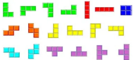
Tetris is a popular computer game invented by a Russian mathematician, named Alexey Pajitnov, in 1985. He derived the game’s name from the Greek numerical prefix “tetra-” and the word specifying one of his favorite sports, “tennis.” “Tetra-” means that all of the game’s pieces, called tetrominoes, contain four segments, each segment being a small square unit. A tetromino is a geometric shape composed of four squares, connected orthogonally. There are five basic types of tetrominoes, and nineteen types of oriented tetrominoes obtained by rotating and reflecting the basic ones. See Fig. 1 for an illustration.
Tetrominoes can be used to fill a plane by a certain arrangement without overlapping. This property makes tetrominoes good components for composing a new type of mosaic image, called
tetromino-based mosaic image, as proposed in this
study. It is desired to propose a method for effective creation of tetromino-based mosaic images from the artistic point of view. Furthermore, it is desired as well to design a new watermarking method for copyright protection of this new type of art image based on the use of information hiding techniques.
Fig. 1: Nineteen types of oriented tetrominoes made of five basic ones.
There are yet few studies on hiding information in art images. Lin and Tsai [9] proposed a method to hide data in mosaic images by manipulating the four borders of tile images. Hung, Wu, and Tsai [10] proposed a method to embed data in tile mosaic images by adjusting the orientations, sizes, and textures of the tiles. Hsu and Tsai [11] proposed a method to hide data in circular-dotted images by a dot overlapping scheme. Wang and Tsai [12] proposed a method for data hiding in tile-overlapping mosaic images by utilizing the overlapping degrees of adjacent tile images.
In this paper, a losslessly-removable visible watermarking method is proposed. A watermark may be embedded into an input tetromino-based mosaic image by replacing the tetromino colors according to a one-to-one mapping between two color palettes constructed from the colors of the watermark area in the input image. The watermark may be losslessly removed from the watermarked image later for better inspection of the original image. The proposed method is useful for copyright protection of tetromino-based mosaic images. Security of the embedded watermarking is enhanced by the use of a secret key. Experimental results are also shown to prove the feasibility of the proposed method.
In the remainder of this paper, we describe the proposed tetromino-based mosaic image creation process in Section 2, the proposed process for
losslessly-removable watermarking in Section 3, and some experimental results in Section 4, followed by conclusions and some suggestions for further studies.
II. PROPOSED TETROMINO-BASED MOSAIC IMAGE CREATION PROCESS
In Section 2.1, the basic idea of proposed tetromino-based mosaic image creation is presented. In Section 2.2, the traditional mosaic image creation is reviewed. In Section 2.3, the tetromino-based mosaic image creation method will be described in detail.
2.1 Idea of Tetromino-based Mosaic Image Creation
The idea of the proposed technique to create tetromino-based mosaic images was inspired by Lin and Tsai [9]. Two goals are considered simultaneously in this study. The first is to integrate art and computer technologies to create images, which look more artistic with special visual effects for decorations or other uses. The second is to use a mosaic image as a medium for data hiding. As a result, the proposed method is applicable to deal with the problem of copyright protection.
In geometry, tetrominoes can be combined adjacently to one another to form square blocks, and blocks so formed can be used to fill a plane. This is the reason why tetrominoes are also good units for mosaic image creation as proposed in this study. However, tiling a plane in this way with tetrominoes is more difficult than traditional mosaic image creation because tetrominoes have more complicated shapes. Consequently, how to combine different kinds of tetrominoes to create a variety of distinct mosaic images is a critical issue. In addition, using tetrominoes as components to generate mosaic images can provide a new style of visual effects for viewers.
2.2 Review of Traditional Mosaic Creation Process
2.2.1 Mosaic Images Creation Process
Two major issues are involved in mosaic image creation, namely, mosaic database construction and similarity measure selection. The former is the first step of the mosaic creation process to generate tile
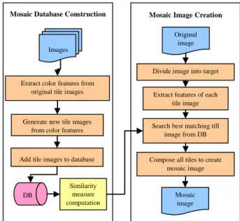
images. Tile images are not only the basic components of mosaic images but also the key components which determine how mosaic images look like. The latter issue is the design of a good measure for use in the process of choosing the best-matching tile image for each target image from a mosaic database. In Lin and Tsai [9], mosaic images were created according to the following procedure. First, a mosaic database was constructed by selecting a set of tile images and then extracting relevant features from them. Next, a source image is taken as input and divided into many small target images with a pre-selected size. A similarity measure is then used to search the best-matching tile images of the same size from the mosaic database for all the target images. Finally, after putting the best-matching tile images together, a mosaic image is generated. A flowchart of such a mosaic image creation process is illustrated in Fig. 2.
Fig. 2: A flowchart of mosaic image creation.
2.2.2 Similarity Measure Computation
In Fig. 1, computation of the similarity measure between a target image and a tile image is mentioned. An input source image is first divided into blocks of small target images and the feature vector of each target image is obtained by calculating the three average color values of the target image in the R, G, and B color channels. The vector extracted from a target image is matched
with the feature vector of each tile image in the mosaic database according to the Euclidean distance measure. The tile image with the smallest distance in the database is finally taken as the best-matching tile for use in composing the output mosaic image. The detailed algorithm of similarity measure computation is described as follows.
Algorithm 1. Similarity measure computation. Input: a target image T and a tile image L.
Output: a similarity measure value D between T
and L.
Steps:
Step 1. Divide T and L into N parts, where N is a pre-defined number.
Step 2. Extract color features from each part of T to form a vector VT with N×3 elements.
Step 3. Extract color features from each part of L to form a vector VL with N×3 elements.
Step 4. Calculate the Euclidean distance between the color vectors VT and VL according to the
following similarity measure: 2
T L
D= V −V .
2.3 Proposed Tetromino-based Mosaic Image Creation Process
In this section, based on above-mentioned traditional mosaic image creation process we show how we create a tetromino-based mosaic image in this study in this section as an algorithm below.
Algorithm 2. Tetromino-based mosaic image
creation.
Input: a source image I, a given size s of one
square in a tetromino, and a tetromino database DB.
Output: a tetromino-based mosaic image I′. Steps:
Step 1. Divide the source image I into a set of target images with the given size s.
Step 2. For each target image T, perform the following operations.
2.1 Calculate the distance between T and each tile image L in database DB by Algorithm 1.
2.2 Choose the tile image LT in DB with the
smallest distance as the best-matching tile image for T.
Divide image into target i
Extract features of each tile image
Search best matching till image from DB
Compose all tiles to create mosaic image
Mosaic image Extract color features from
original tile images
DB
Generate new tile images from color features
Mosaic Image Creation
Original image Images
Mosaic Database Construction
Similarity measure computation Add tile images to database
2.3 Perform a border enhancement process to enhance the visual effect of each tetromino in T (the detail described later). Step 3. Replace each target image T in I with its
corresponding best-matching tile image LT
to create a tetromino-based mosaic image I′ as output.
In the above steps, the best-matching tile image, which is the most similar to the corresponding target image, is found by in the use of Algorithm 1. The construction of the tetromino database DB mentioned in the above algorithm is described in the next section.
2.3.1 Tetromino Database Construction
The tetromino database is used to find the best-matching tile image for each target image, as described in the previous algorithm. It is desired to control the number of colors and combinations of the tetrominoes in the database. Before tetromino database construction, we have to design an algorithm to enumerate all the possible tetromino combinations in a fixed-sized region. Nineteen types of tetrominoes, as shown in Fig. 1, are used as input. In this study, the fixed-sized region is a plane of 4×4 grids as shown in Fig. 3(a). An example is shown in Fig. 3(b). The details of the enumerating process of tetromino combinations and the proposed process of tetromino database construction are described as Algorithms 3 and 4 below.
Fig. 3: Illustrations of tetromino combinations. (a) A plane of 4×4 grids. (b) A tetromino combination in (a).
Algorithm 3. Enumeration of tetromino
combina-tions.
Input: 19 types of tetrominoes E and a plane P of
4×4 grids.
Output: a set of all possible tetromino
combinations T = {T1, T2, .., Tn} in P. Steps.
Step 1. Create a four-level tree R with a root r. Step 2. At the first level, for each tetromino type X
in E, perform the following operations. 2.1 For each position which can be used to place
X, perform the following operations. 2.1.1 Generate a child node Cr of root r.
2.1.2 If the filled tetromino X crosses the boundary of P, delete Cr and go back to
Step 2.1.
2.1.3 Record the tetromino type X and the position of X in Cr.
Step 3. For each node of level Li, where 2 ≥ i ≥ 4,
perform the following operations.
3.1 For each node D in level i − 1, perform the following operations.
3.1.1 Choose one type from E and denote it by Y.
3.1.2 For each position which can be used to place Y, perform the following operations.
3.1.2.1 Generate a child node Ck of node D.
3.1.2.2 If the filled tetromino Y crosses the boundary of P, delete Ck and go back
to Step 3.1.2.
3.1.2.3 If the filled tetromino Y overlaps with any existing tetromino, delete Ck and go back to Step 3.1.2.
3.1.2.4 If the filled tetromino combination Y already exists in the tree, delete Ck
and go back to Step 3.1.2.
3.1.2.5 Record the tetromino type and the position of Y in Ck.
Step 4. Through a tree traversal, search all paths from all leaves in level 4 to the root.
Step 5. For each path Pi in the tree, form a
tetromino combination Ti by extracting data
from each node of Pi.
Algorithm 4. Tetromino database construction. Input: 19 types of tetrominoes, and a fixed number
N of colors.
Output: a tetromino database DB with all possible
tile images.
Steps:
combinations T = {T1, T2, .., Tn} in a plane
of 4×4 grids by Algorithm 3.
Step 2. Generate a set of N distinct colors, C = {C1, C2, .., CN}, in the RGB color space
uniformly.
Step 3. Create all possible tile images by generating all possible combinations of Ti
in T and Ci in C.
2.3.2 Visual Effect Improvement by Border Enhancement
Through the above-proposed algorithms, basic tetromino-based mosaic images can be created. However, a problem occurs in the creation process. That is, if two adjacent tetrominoes have similar colors, the edge between them will be unclear, yielding an undesirable effect in the resulting mosaic image. It is desired to enhance the boundary of tetrominoes in basic tetromino-based mosaic images. Furthermore, it is also desirable to make each piece of tetrominoes look like a three-dimensional object. As a result, two visual effects, lightening and shading borders, are created in this study in a post-processing process after the above basic tetromino-based mosaic image creation process, which we call border enhancement. The process is described as an algorithm in the following.
Algorithm 5. Border enhancement.
Input: a plane Y of 4×4 grids with a tetromino
combination P.
Output: Y with lightening and shading effects P′. Steps:
Step 1. For each tetromino t in P, transform the color of the tetromino from the RGB model to the HSL model (with H, S, and L channels).
Step 2. For each tetromino t in P, check the type of each of its four edges in the follow way. 2.1 If it is a top or left edge in t, then lighten the
edge by increasing the L channel value of the color at the corresponding border.
2.2 If it is a bottom or right edge in t, then shade the edge by decreasing the L channel value of the color at the corresponding border.
2.4 Some Experimental Results of Mosaic Image Creation
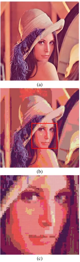
Some tetromino-based mosaic images created in our experiments by the use of a tetromino database with 125 colors and 117 tetromino combinations constructed in this study are shown here. Fig. 4(a) is the input image. Fig. 4(b) is the mosaic image created from Fig. 4(a) by applying Algorithm 2. And Fig. 4(c) is an enlarged version of the partial image composed of some tetrominoes in the red region shown in Fig. 4(b).
III. Proposed Method for losslessly removable watermarking in tetromino-based mosaic
images
3.1 Idea of Proposed Data Hiding Method
In order to protect the copyright of images, many digital watermarking techniques have been designed to embed a pre-defined watermark into an image. Digital watermarking techniques may be classified into two main types, visible and invisible watermarking, by their visual characteristics. Different from invisible watermarking techniques, visible watermarking techniques can be used to convey ownership information directly and deter further copyright violations. As a result, visible watermarking is a suitable way to protect copyrights of art images.
Obviously, having a fixed number of colors is a common feature between palette images and tetromino-based mosaic images. Based on this observation and the concept of Chen and Tsai’s method [13], we propose in this study a removable lossless visible watermarking method for tetromino-based mosaic images. The details are described in the following sections.
3.2 Review of A Losslessly-Removable Visible Watermarking Technique for Palette images
The losslessly-removable visible watermarking method proposed by Chen and Tsai [13] are applicable to palette images of the GIF (graphics interchange format) type. Every GIF image contains at most 256 colors stored in an 8-bit color palette. Each color in the palette is assigned a number, called an index. Every pixel in the GIF image is assigned an index number corresponding to the color of the pixel. Furthermore, each GIF image can be compressed to reduce the file size without degrading the visual quality.
Before describing the proposed method, some definitions of terms are given below.
1. Watermark area: an area in a cover image where a watermark is embedded.
2. Non-watermark area: an area outside the watermark area.
3. Black embedded pixels: the pixels of the cover image in the watermark area, denoted as Ib.
4. White embedded pixels: the pixels of the cover image in the non-watermark area, denoted as Iw.
Each visible watermark is assumed to be a binary image. In order to enable the embedded watermark area to look more obvious, Chen and Tsai [13] replaced the colors of Ib with other
visually-different colors. This replacement was achieved by the use of the farthest (the most different) color among the palette colors of the cover image. First, the cover image was divided into a watermark area and a non-watermark one. Black embedded pixels Ib were replaced with other
colors and white embedded pixels Iw were kept
unchanged. Then, a raw color palette is constructed by identifying the distinct colors in Iw and counting
the occurrences of these colors. Let them be denoted as C = {C0, C1, …, C255} and their
corresponding numbers of occurrences as O = {O0,
O1, …, O255}. The raw color palette was sorted by
the colors Oi in O in a descending order to generate
a sorted color palette Ps. An adjusted Euclidean
distance by considering the concept of weighting, called weighted Euclidean distance, was proposed. Specifically, the traditional Euclidean distance between two colors C1 and C2 is defined by Eq. (1)
below: 2 2 1 2 2 1 2 2 1 2 1, ) ( ) ( ) ( ) (C C = R−R + G −G + B −B µ ; (1)
and the weighted one of color Ci in the color palette
is defined by Eq. (2) below:
∑
∑
= = × = 255 0 255 0 ) , ( ) ( n n n i n n i O C C O C µ µ . (2)Second, Chen and Tsai [13] chose the farthest color Cf from the sorted color palette by using the
weighted Euclidean distance described by (2), (a)
(b)
(c)
Fig. 4: Experimental results of tetromino-based mosaic image creation. (a) An original image. (b) A created mosaic image. (c) Enlarged image part of red region in (b).
which is the most different color from the colors of Iw. Then, a rearranged color palette Pr is set up by
placing Cf as the first element in the palette, the
color Ca closest to Cf as the second element, and
that closest to Ca as the third, and so on. In such a
way, a one-to-one mapping between the two palettes Ps and Pr is established. If a color Cm was
labeled by index m in Ps, then this color is mapped
to a color Cm′ which was labeled by index m in Pr.
All black embedded pixels in the cover image are then replaced to generate a watermarked image by the above-mentioned replacement using the mapping. Furthermore, a lossless recovery of the watermarked image can be achieved, which is an inverse process of the above-proposed watermark embedding process.
3.3 Visible Watermark Embedding Process
We now describe the visible watermark embedding method for tetromino-based mosaic images proposed in this study. First, a raw palette is constructed by counting the occurrences of the colors in a tetromino-based mosaic image. By using the raw palette, a process of generation of two color palettes, which are denoted as Ps and Pr, and a
mapping process between them are performed for watermarking. At last, the colors of the black embedded pixels Ib are replaced by using the
one-to-one mapping between Ps and Pr. The details
of such watermark embedding is described as follows as an algorithm.
Algorithm 6. Visible watermark embedding in
tetromino-based mosaic images.
Input: a tetromino-based mosaic image I, a binary
watermark W, and a secret key K.
Output: a watermarked tetromino-based mosaic
image I′.
Steps:
Step 1. For each tetromino t in I, perform the following steps.
1.1 If t is in the watermark area, add all pixels in t into a set of black embedded pixels Ib.
1.2 If t is in the non-watermark area, add all pixels in t into a set of white embedded pixels Iw.
Step 2. Create a raw color palette Pa by identifying
the colors C = {C0, C1, …,Cn} in I and
denote the number of color elements of Pa
as n.
Step 3. For every pixel in Iw, count the occurrences
of the colors in C = {C0, C1, …,Cn},
respectively, and denote them as O = {O0,
O1, …,On}.
Step 4. Use Pa, C, and O to generate a sorted color
palette Ps and a rearranged color palette Pr
by Algorithm 7 described below.
Step 5. For each pixel p in Ib, embed W into I by the
following steps.
5.1 Obtain the color Cm of p.
5.2 Search Cm in Ps to obtain a color index m
of Cm.
5.3 Obtain the color Cm′ in Pr with the index
m.
5.4 Replace the color Cm of p with Cm′.
Step 6. Randomly pair every two pixels of Ib
together using the key K to form |Ib|/2 pairs
of pixels as a set A.
Step 7. For each pair a in A, swap the two colors of a to generate a watermarked image I′.
The use of the input secret key in the way described in Steps 6 and 7 above increases the security of the embedded watermark against illicit trials of removal of the watermark from the watermarked image.
Algorithm 7. Creation of two color palettes for
one-to-one color mapping (mentioned in Step 4 of Algorithm 6).
Input: a raw color palette Pa, a set of colors C =
{C0, C1, …, Cn} of Pa, and a set of
occurrences O = {O0, O1, …, On}
corresponding to C.
Output: a sorted color palette Ps and a rearranged
color palette Pr. Steps:
Step 1. Sort Pa by the occurrences O in a
descending order to obtain a sorted color palette Ps.
Step 2. Create an initially-empty rearranged color palette Pr, which is of the same size of Ps.
Step 3. Calculate the weighted Euclidean distance Dw of every color in Ps by Eq. (2).
Step 4. Use the values of all Dw’s to choose a color
Cf which has the largest value of Dw to be
Step 5. Calculate the Euclidean distance D between Cf and every other color in Ps by Eq. (1).
Step 6. Use the values of D’s to construct Pr by
rearranging the colors in Ps with the nearest
color to Cf being the second element in Pr
and the farthest color to Cf being the last. 3.4 Lossless Recovery Process of Original
Images by Removing Visible Watermark
In this section, we describe the proposed lossless recovery process of the original image by removing the visible watermark in a watermarked image. First, a raw palette is constructed by counting the colors of the watermarked image. By using the raw palette, generation of two color palettes, Ps and Pr,
like those mentioned previously in Algorithms 6 and 7 are performed. At last, we replace the colors of the black embedded pixels Ib to recover the
original tetromino-based mosaic image by using the mapping between Ps and Pr. The detailed algorithm
of the proposed lossless recovery process is described as follows as an algorithm.
Algorithm 8. Lossless recovery of a tetromino-
based mosaic image.
Input: a watermarked tetromino-based mosaic
image I, a binary watermark W, and a secret key K used in Algorithm 6.
Output: a recovered tetromino-based mosaic
image I′.
Steps:
Step 1. For each tetromino t in I, perform the following steps.
1.1. If t is in the watermark area, add all pixels in t into a set of black embedded pixels Ib.
1.2. If t is in the non-watermark area, add all pixels in t into a set of white embedded pixels Iw.
Step 2. Create a raw color palette Pa by identifying
the colors C = {C0, C1, …,Cn} in I and
denote the number of color elements of Pa
as n.
Step 3. For every pixel in Iw, count the occurrences
of the colors in C = {C0, C1, …, Cn},
respectively, and denote them as O = {O0,
O1, …, On}.
Step 4. Use Pa, C, and O to generate a sorted color
palette Ps and a rearranged color palette Pr
by Algorithm 7.
Step 5. Randomly pair every two pixels of Ib
together using K to form |Ib|/2 pairs of
pixels as a set A.
Step 6. For each pair a in A, swap the two colors of a.
Step 7. For each pixel p in Ib, remove W from I to
generate a recovered palette image I′ by the following steps.
7.1. Obtain the color Cn of p.
7.2. Search Cn in Pr to obtain a color index n of
Cn.
7.3. Obtain the color Cn′ in Ps with the index n.
7.4. Replace the color Cn of p with Cn′.
Note that without the correct key K used in creating the watermarked image using Algorithm 6, the lossless recovery of the original image cannot be achieved, as can be seen from Steps 5 and 6.
IV. Experimental Results
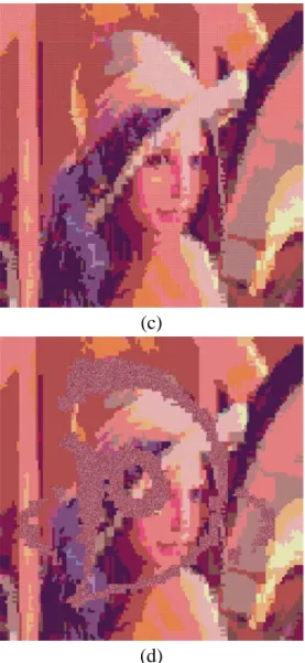
Fig. 5 shows a binary watermark used in experiments conducted in this study. Fig. 6 shows some corresponding results of applying the proposed method, in which Fig. 6(b) is a watermarked tetromino-based mosaic image yielded by the proposed watermark embedding process (Algorithm 6) with Fig. 4(a) as the input image and Fig. 5 as the input watermark. Fig. 6(c) is a losslessly-recovered image extracted from Fig. 6(b) with a correct key by the proposed lossless recovery process (Algorithm 8). Fig. 6(d) shows an erroneously-recovered image extracted from Fig. 6(b) with a wrong key. As seen in these experimental results, the embedded watermark area looks visually different from the pixels adjacent to them. In addition, the watermark can be removed losslessly with the right key. These results show the feasibility and applicability of the proposed method.
V. Conclusions
In this study, we have proposed a new type of art image, namely, tetromino-based mosaic image, and a method for creation of it. Also proposed is a data
hiding method for losslessly-removable visible watermarking. Using the properties of tetromino-based mosaic images, we have designed an algorithm for embedding a visible binary watermark into a cover image by replacing the colors of the watermark area according to a novel one-to-one mapping between two color palettes generated from the input original image and the watermark. As a result, it can be used for the purpose of copyright protection of tetromino-based mosaic images. Also, a process for lossless recovery of the original tetromino-based mosaic image from a watermarked image has been proposed, which is an inverse process of the watermarking process. Accordingly, authorized users can remove the embedded watermark losslessly from the watermarked image for better inspection of the original mosaic image. Some experimental results generated by the proposed watermarking algorithms were shown to prove the feasibility of the proposed method. Future researches may be directed to applying the proposed technique of data hiding behind the watermarking process for other applications of information hiding.
References
[1] P. Haeberli, “Paint by Numbers: Abstract Image Representations,” Proceedings of SIGGRAPH 90, pp. 207-214, Dallas, Texas, USA, 1990. [2] A. Hausner, “Simulating decorative mosaics,”
Proceedings of SIGGRAPH 01, pp. 573-580, Los Angeles, CA, USA, Aug. 2001.
[3] K. Hoff, J. Keyser, M. Lin, D. Manocha and T. Culver, “Fast computation of generalized voronoi diagrams using graphics hardware,” Proceedings of SIGGRAPH 99, pp. 277-286, Los Angeles, CA, USA, Aug. 1999.
[4] S. Lloyd, “Least Square Quantization in PCM,” IEEE Transactions on Information Theory, vol. 28, pp. 129-137, 1982.
[5] Y. Dobashi, T. Haga, H. Johan and T. Nishita, “A method for creating mosaic images using
voronoi diagrams,” Proceedings of
Eurographics 02, pp. 341–348, Saarbrucken, Germany, Sept. 2002.
[6] G. M. Faustino and L. H. De Figueiredo,
“Simple adaptive mosaic effects,” Proceedings of SIBGRAPI 2005, Natal, Brazil, Aug. 2005. [7] G. D. Blasi and G. Gallo, “Artificial Mosaics,”
The Visual Computer, vol. 21, pp. 373-383, 2005.
[8] G. Elber and G. Wolberg, “Rendering traditional mosaics”, The Visual Computer, vol. 19, pp. 67-78, 2003.
[9] W. L. Lin and W. H. Tsai, “Data hiding in image mosaics by visible boundary regions and its copyright protection application against print-and-scan attacks,” Proceedings of International Computer Symposium 2004, Taipei, Taiwan, Dec. 2004.
[10] S. C. Hung, D. C. Wu, and W. H. Tsai, “Data hiding in stained glass images,” Proceedings of 2005 International Symposium on Intelligent Signal Processing and Communications Systems, pp. 129-132, Hong Kong, Dec. 2005. [11] C. Y. Hsu and W. H. Tsai, “Creation of a new
type of image - circular dotted image - for data Hiding by a dot overlapping scheme,” Proceedings of 2006 Conference on Computer Vision, Graphics and Image Processing, Taoyuan, Taiwan, Aug. 2006.
[12] T. C. Wang and W. H. Tsai, “Creation of tile-overlapping mosaic images for information hiding,” Proceedings of 2007 National Computer Symposium, pp. 119-126, Taichung, Taiwan, Dec. 2007.
[13] P. P. Chen and W. H. Tsai, “Copyright protection of palette images by a robust lossless visible watermarking technique,” Proceedings of 5th Workshop on Digital Archives Technologies, Taipei, Taiwan, Aug. 2006.
(a)
(b)
Fig. 6: An experimental result. (a) Input image. (b) Watermarked image created from (a) with Fig. 5 embedded. (c) Recovered image obtained with a right key. (d) Recovered image obtained with a wrong key.
(c)
(d)
Fig. 6: An experimental result. (a) Input image. (b) Watermarked image created from (a) with Fig. 5 embedded. (c) Recovered image obtained with a right key. (d) Recovered image obtained with a wrong key. (continued)