A NOVEL IRIS RECOGNITION USING
STRUCTURAL FEATURE OF COLLARETTE
Shun-Hsun Chang
VIP-CCLab., Dept. of Electrical Engineering, National Chi Nan University, Taiwan
Wen-Shiung Chen
VIP-CCLab., Dept. of Electrical Engineering, National Chi Nan University, Taiwan.
Abstract―This paper presents a novel idea based on a kind of structure-based pattern, such as collarette, embedded in human iris for biometric recognition. The feature extraction module traces the collarette. The system encodes the features to generate its iris feature codes. Finally, the recognition module uses these feature codes for iris matching. The experimental results show that the system has an encouraging performance against the UBIRIS iris image database. The recognition rates up to 98.09%, 97.61%, and 96.35%, respectively, using 512-bit, 256-bit and 128-bit iris codes can be achieved.
Index Terms―Biometric Recognition, Iris, Structural Feature, Collarette.
1. INTRODUCTION
The iris, a kind of physiological biometric feature with genetic independence, contains extremely information-rich physical structure and unique texture pattern, and thus is highly complex enough to be used as a biometric signature [1] means of authentication. After Flom and Safir [2] observed the fact that every iris has a highly detailed and unique texture that remains stable over decades of life, they proposed the concept of automated iris recognition in 1988, however, finally did not realize.
For feature extraction, we are always interested in what kind of features can be used for recognition. For all features can be divided into three classes: statistical, algebraic and structural features. Statistical features use many statistical values for small blocks of an iris image. Randy P. Broussard et al. [3] used statistical values (i.e., mean, standard deviation, skewness, kurtosis, et
al.) for recognition. Algebraic features can be
divided into two classes: transform-based and projection-based. The algebraic feature class develops most literature for iris recognition. The transform-based class includes wavelet transform, discrete cosine transform, Gabor filter and so on. In 1993, Daugman developed a successful system by using the 2-D Gabor wavelet transform [4]. The projection-based includes PCA, LDA and ICA. Bae et al. [5] projected the iris signals onto a bank of basis vectors derived by independent components, analyzed and quantized the resultant projection coefficients as features. The structural feature class liked minutiae-based approach for fingerprint recognition systems. V. Conti et al. use micro-features in their recognition system [6]. The individualized characteristics such as nucleus, collarette, valleys and radius are detected.
Collarette (see Fig. 1) is one of the most important features of iris patterns, since it is usually insensitive to the pupil dilation. Kaushik Roy et al. detect the zigzag collarette area for iris localization [7], [8]. Hanho Sung et al. use 1-D FFT to find the collarette boundary [9]. In these papers, the collarette always use for localization. V. Conti et al. use micro-features in their system [6]. The considered features are nucleus, collarette, valleys and radius. In collarette extraction, they use a 4×4 convolution mask to label the same grey level in all image regions. This algorithm detects the points of collarette that can not represent the character of collarette. The collarette should be a curve for iris region. However, we believe that collarette is circular curve that has enough features for recognition. Thus, we propose the
algorithm to trace the collarette in feature extraction module.
Fig. 1: Typical human eye and collarette. 2. SYSTEM OVERVIEW AND PRE-PROCESSING 2.1. System Overview
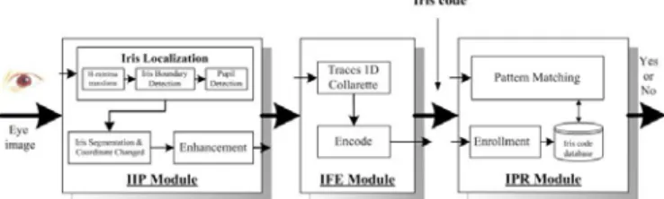
The proposed framework consists of three modules: image pre-processing, feature extraction, and recognition modules, as shown in Fig. 2. Since the system is tested against the UBIRIS iris image database [10], this paper takes no account of the iris image acquisition module. The entire system flow is briefly described as follows. Firstly, the iris image pre-processing module (IIP module) employs some image processing algorithms to demarcate the region of interest (i.e., iris zone) from the input image containing an eye. It performs three major tasks: iris localization, iris segmentation and coordinate transform, and enhancement for the input iris image. Next, the feature extraction module (IFE module) tracks one dimension collarette features, and applies appropriate coding methods on these features to generate the iris feature code. Finally, the iris pattern recognition module (IPR module) employs a minimum distance classifier according to Euclidean distance metric to recognize the iris pattern by comparing the iris code with the enrolled iris codes in the iris code database.
Fig. 2: Structure diagram of the proposed iris recognition system.
2.2. Pre-Processing Module
An input image does contain not only useful information from the iris zone but also useless data derived from the surrounding eye region. Before extracting the features of an iris, the input image must be pre-processed to localize, segment and enhance the region of interest (i.e., iris zone). The system normalizes the iris region to overcome the problem of a change in camera-to-eye distance and pupil’s size variation derived from illumination. Furthermore, the brightness is not uniformly distributed due to non-uniform illumination; the system must be capable of removing the effect and further enhancing the iris image for the following feature extraction. Hence, the image pre-processing module is composed of three units: iris localization, iris segmentation and coordinate transform, and enhancement units, as shown in Fig. 3.
2.2.1. Iris Localization Unit
In this unit, we must first determine the useful part (i.e., iris) from an input image. The iris is an annular region between the pupil and the sclera. The inner and outer boundaries of an iris can be treated as non-concentric circles approximately. In order to make the iris localization efficient, the system performs an operation of enhancing principal edges and blurring useless edges on the copied and down-sample image instead of the original one. Following that, the system estimates the center coordinates of the iris first. Since the iris typically is darker than the Sclera and its gray level distribution has a small variance, the system uses Extended Minima (EM) morphology operator [11]. By choosing an appropriate scalar in EM transform, a perfect edge of outer boundary is obtained. The value of threshold is decided according to the histogram [12].
Fig. 3: Pre-processing module.
2.2.2. Iris Segmentation and Coordinate Transform Unit
The localized iris zone demarcated from the human eye is transformed from rectangular into polar coordinate system so as to facilitate the following feature extraction module [11]. Daugman’s system uses radial scaling to compensate for overall size as well as a simple model of pupil variation based on linear stretching [4]. This scaling serves to map Cartesian image coordinates to dimensionless polar image coordinates (see Fig.4). The system generates a rectangular iris image of a fixed size by linear interpolation. The image size of iris is 512×128. Fig. 5(a) shows an example of the iris segmentation and normalization.
Fig. 4: Mapping of Cartesian image coordinates to dimensionless polar coordinates.
2.2.3. Enhancement Unit
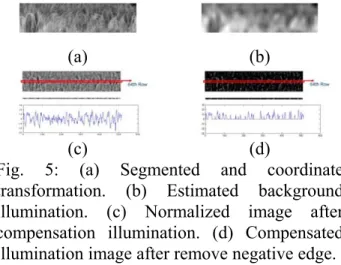
The normalized iris is easily affected by the non-uniform illumination and may have low contrast. The final step of the IIP module is to perform image enhancement in order to obtain a well-distributed texture image. The enhancement algorithm used mean mask from the normalized iris image to compensate for the non-uniform illumination (see Fig. 5(b)). In these images, we can find many special textures in the iris zone (nucleus, collarette, radius, etc.). They are always brighter than the other zone. The 64th row iris signal is shown in Fig. 5(c). It includes many dark parts in which we are not interested, because we can see the collarette which is always brighter than the other region in iris zone. In order to obtain better collarette signal, we remove negative edge for iris images (see Fig. 5(d)).
(a) (b)
(c) (d) Fig. 5: (a) Segmented and coordinate
transformation. (b) Estimated background illumination. (c) Normalized image after compensation illumination. (d) Compensated illumination image after remove negative edge.
3. FEATURE EXTRACTION 3.1. Characteristics of Collarette
The iris is divided into two major regions: The pupillary zone and the ciliary zone. The pupillary zone is the inner region which edge forms the boundary of the pupil and the ciliary zone is the rest of the iris that extends to its origin at the ciliary body. The collarette is the region of the iris separating the pupillary portion from the ciliary portion. It is typically defined as the region where the sphincter muscle and dilator muscle overlap (see Fig. 6(a)) [1]. It is easy to trace the collarette from most of human iris (see Fig. 1 and Fig. 6(b)).
Some human iris areas are smooth or iris images are out of focus. Those images are difficult to detect collarette like Fig. 6(c). Therefore we use the statistic idea that can trace the collarette.
(a)
(b) (c) Fig. 6: Anatomy of the human iris. (a) The
structure of the iris seen in a frontal sector. The visual appearance of the human iris derives from its anatomical structure. (b) Collarette is easy to be detected. (c) The iris area is smooth.
3.2. Feature Extraction Using Collarette Detection The positive edge structures in iris images are often the most important features for pattern recognition. We use easy and fast algorithm to trace the collarette for enhancing iris images. We have carefully observed the collarette on iris images, which appears it is uninterrupted. After normalized, we assume that the collarette is a continuous line and its width is usually between 3 to 9 pixels (see Fig. 7). It can be described in the following algorithm:
Input Image: Iris image was enhanced by IIP
module I(128×512).
Input Parameters: SR is the search range in iris
image, and CW is collarette’s width in iris image.
Output: The sequence of collarette Icol(1×512).
Step 1: Reducing Noise.
Use low-pass filter to reduce Gaussian noise.
) (lowpass filter I
IH= ∗
Step 2: Find the initial value on column
for input iris image.
1
col
I 1st
1
col
I is maximum of the mean of the
collarette width. ) ) 1 , ( ( max arg 2 ) 1 ( 2 ) 1 ( 1 CW i I i I CW i CW i H i col
∑
+ − − − = =Where i is an index on 1st column (1~128).
Step 3: Find the next value on using image
energy in next column. col
I
Calculate the energy of the collarette width from search range.
∑
= = − + − − = − − jSR jSR c jSR H C jSR colj j col j col jSR j c I c I SR I to SR I c ) , ( max arg 2 ) 1 ( 2 ) 1 ( ( 1) ) 1 (Where j is an index of other column (2~512).
Step 4: Error compensation for excluding search
range.
We compensate the energy excluding search range. ⎪ ⎩ ⎪ ⎨ ⎧ + = < = = − = > =
∑
−∑
= + = 1 , 1 , 1 1 , 1 ) , ( ) , ( 128 1 1 1 colj colj colj colj colj colj c k c k I I r I I r I I r j k I j k I r jSR jSRwhere k is an index of column (1~128) and r is ratio of up part energy to down part energy.
th
j
Step 5: Repeat Step 3 to Step 4 until j reaches to
512, and record Icolj.
Fig. 7: The width of collarette.
Finally, we get the sequences of collarette and show the iris images in Fig. 8.
(a) (b) Fig. 8: (a) The collarette for same class. (b) The
collarette for different classes.
3.3. Feature Encoding Based On Collarette
We get one-dimensional sequence after record . It is resulted from tracing collarette from iris image. Lastly, we use Delta Modulation (DM) and Gradient Modulation (GM) methods to code the collarette sequence.
colj
I
Delta modulation (DM or Δ-modulation) and gradient modulation (GM) are an analog-to-digital and digital-to-analog signal conversion technique used for transmission of voice information where quality is not of primary concern. Gradient modulation (GM) only detects the gradient of signal.
3.4. Pattern Recognition Module
In this module, the feature code vector extracted from the claimant iris image is compared against those of the enrolled feature code vectors in an iris database we created. Here for simplicity, we adopt the mean vector as the prototype of each pattern class in the enrollment phase and utilize the minimum distance classifier to check the approach in the recognition phase [13].
4. EXPERIMENTAL RESULTS
To evaluate the performance of the proposed human iris recognition system, we implemented and tested the proposed schemes on the UBIRIS iris image database [10], built by University of Beira, Soft Computing and Image Analysis Group. The database comprises 1,205 iris images captured from 241 different eyes (hence, 241
classes). Each original iris image has the resolution of 800×600 in RGB format.
In a verification system, the performance can be measured in terms of three different factors: (1) False Acceptance Rate (FAR), (2) False Rejection Rate (FRR) and (3) Equal Error Rate (EER). Finally, the relationships between recognition rates and parameters are tested in our experiments.
4.1. Results of Image Pre-Processing
We check the accuracy of the boundaries (including pupil, iris, and lower eyelid) subjectively. The proposed system obtains the success rate of 87.22% (1,051 images) from 1,205 images in the experiments for the pre-processing module. Table 1: shows the summary of the causes of failure of image pre-processing.
Among those 1,051 images obtained successfully from the image pre-processing module, we select 975 images (195 classes) out of them for testing (enrollment and recognition). We train the system by selecting 3 images as the training images set for each person from the authorized users in the enrollment phase.
Table 1: Analysis of causes of failure for the image pre-processing module.
Causes of Failure # of Data Ratio (%) (1) Non-uniform illumination 45 29.22 (2) Occlusion by eyelids or eyelashes 73 47.4 (3) Closed eye 11 7.14
(4) Affected by iris texture 22 14.29
(5) etc. 3 1.59
Total 154 100
4.2. Results of the DM and GM
In this experiment, we test the recognition performance for the DM and GM. To obtain a threshold separating FRR and from FAR, we perform two tests, one is for false rejection test and the other is for false acceptance rate test. For
the case of FRR, we can obtain the distribution of non-matching distance between the unknown classes and the registered classes. For the case of FAR, we also obtain the distribution of non-matching between the unknown classes for impostors and the registered classes. Fig. 9(a) shows the distributions of the above two experiments for DM. In these figures, the x-axis and y-axis indicate the degree of distance and the amount of data.
Fig. 9(b) shows the plots of the variation of FRR and FAR according to the distribution of non-matching distance by selecting a proper distance threshold. When we set the threshold to 12.5083 for DM, the system obtains the recognition performance of about EER=1.9098%. The performances of DM are better then performances of GM in our system.
Although, these results can be improved, the algorithm is simple, fast and code lengths are very short. The Daugman’s system [4] has almost perfect performance, but the system’s code lengths are 2,048 bits (256 bytes). The proposed system only needs, at most, 512 bits (64 bytes). Since the code length is shorter than others’, next procedure for the pattern recognition module would be completed in short-term. Table 2 shows the results of relationship between recognition rate and code length.
7 8 9 10 11 12 13 14 15 16 17 0 0.5 1 1.5 2 Distance D en sity ( % ) same-eye different-eye 7 8 9 10 11 12 13 14 15 16 17 0 10 20 30 40 50 60 70 80 90 100 Threshold Er ro r r ate %
EER = 1.9098% (while Threshold = 12.5083) FRR FAR
Fig. 9: (a) the distribution of non-matching distance, (b) variation of FRR and FAR.
Table 2: Relationship between recognition rates and code lengths.
Feature codes DM GM 512 bits 1.9098 4.1968 256 bits 2.3853 4.2589 EER (%) 128 bits 3.6517 6.6186 64 bits 6.4018 10.3555 32 bits 11.3909 16.2585 16 bits 19.6225 26.3080 4.3. Results of the Parameters
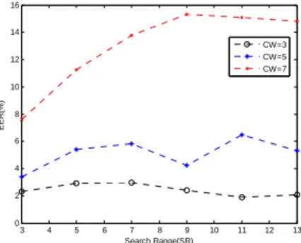
In our system, the IFE module need to input parameters, such as SR and . Parameters have effect on recognition rate. In this experiment, we change the parameters and observe the relationship between recognition rate and different parameters with DM (see Fig. 10). The best result can detect in our system. In this system, the parameters SR and , respectively, using 3 and 11. The system has best performance that up to 98.09%. CW CW 3 4 5 6 7 8 9 10 11 12 13 0 2 4 6 8 10 12 14 16 Search Range(SR) EER (% ) CW=3 CW=5 CW=7
Fig. 10: Relationship between recognition rate and different parameters.
5. CONCLUSION
In this paper, a novel human iris recognition based on structural feature, such as collarette, has been proposed. The good performance of recognition rate reveals that the structure-based approach has high potential. In From the experimental result, it is shown that the proposed iris recognition technique is suitable for the environment in low security level and high speed security system.
6. REFERENCES
[1] R. P. Wildes, “Iris recognition: an emerging
biometric technology,” Proceedings of the IEEE, vol. 85, no. 9, pp. 1348-1363, Sep. 1997.
[2] L. Flom and A. Safir, “Iris recognition
[3] R. P. Broussard, L. R. Kennell, D. L. Soldan
and R. W. Ives, ”Using artificial neural networks and feature saliency techniques for improved iris segmentation,” International Joint Conf. on Neural Networks, pp. 1283-1288, Aug. 2007.
[4] J. G. Daugman, “High confidence visual
recognition of persons by a test of statistical independence,” IEEE Trans. on Pattern Analysis and Machine Intelligence, vol. 15, no. 11, pp. 1148-1161, Nov. 1993.
[5] K. Bae, S. Noh and J. Kim, “Iris feature
extraction using independent component analysis,” Inf. Conf. Audio and Video-Based biometric Person Authentication, pp. 838-844, 2003.
[6] V. conti, G. Milici, F. Sorbello and S.
Vitabile, “A novel iris recognition system based on micro-features,” Automatic Identification Advanced Technologies, pp. 253-258, June 2007.
[7] K. Roy and P. Bhattacharya, “Collarette area
localization and asymmetrical support vector machines for efficient iris recognition,” International Conf. on Image Analysis and Processing (ICIAP), pp. 3-8, Sept. 2007.
[8] K. Roy and P. Bhattacharya, ”Optimal
features subset selection and classification for iris recognition,” EURASIP Journal on Image and Video Processing, Vol. 2008, Article ID 743103, 20 pages, 2008.
[9] H. Sung, J. Lim, J. Park and Y. Lee, “Iris
recognition using collarette Boundary Localization,” Proc. of Int. Conf. on Pattern Recognition, vol. 4, pp. 857-860, 2004
[10] H. Proenc and L. A. Alexandre, Ubiris Iris
Image Database, http://iris.di.ubi.pt.
[11] A. Poursaberi and B. N. Araabi, “A novel iris
recognition system using morphological edge detector and wavelet phase features,” ICGST International Journal on Graphics, Vision and Image Processing (GVIP), vol. 5, no. 6, pp. 9-15, Jun. 2005.
[12] R.-H. Huang, W.-S. Chen, L. Hsieh, S.-H.
Chang,“ Personal authentication using human iris recognition based on 3D
co-occurrence matrix,” 2008 21th IPPR Conference on Computer Vision, Graphics and Image Processing (CVGIP'2008), Yilan, Aug. 24-26, 2008.
[13] R. C. Gonzalez and R. E. Woods, Digital
Image Processing, 2nd Edition, Prentice-Hall, New Jersey, 2002.