Dual Mode Control of a System with Friction
Shih-Jung Huang, Jia-Yush Yen,
Member, IEEE,and Shui-Shong Lu
Abstract—The stick-slip friction system is known to exhibit very
different macro and microscopic behaviors. For large movements, the system exhibits the familiar stick-slip friction characteristics; and for very fine movements, the elastic deformation seems to prevail. While there have been tremendous efforts to understand the stick-slip friction mechanism, most people would agree that the complexity of the friction characteristics prevents the estab-lishment of a simple mathematical model. Thus, the controller design cannot be solely dependent on a friction model. In this paper, a robust controller is developed so that it achieves ultimate
boundedness in both the macro and micro motion regions. As a
result, the controller is capable of controlling the system across the macro movement range and achieves precision positioning in the micro motion resolution. Comparisons with the existing controllers also show that the proposed controller easily achieves a better performance.
Index Terms—Lyapunov methods, mechanical factors, position
control, robustness, servosystems.
I. INTRODUCTION
T
HE stick-slip friction system is known to exhibit very different macro and microscopic behavior [1]. From the macroscopic point of view, the system is treated as stationary within the static friction region. As the applied force grows strong enough to break the stick friction, the friction force will suddenly drop to a velocity dependent slip-friction. The microscopic behavior, on the other hand, treats the very small movements within the static friction region. As the applied force increases, the system actually undergoes a very small movement; and the movement is almost proportional to the applied force. This movement can be the result of the microscopic deformation of the bonding between the contacting surfaces, and can represent a detectable error when the requirement on system accuracy is high.The stick-slip friction system has been the focus of many research interests. Several popular friction models are available in the literature [1]–[6]. Among these models, the Bristle model by Haessig and Friedland [1] captures the most detailed physical phenomenon. The reset integrator model by Haessig and Friedland [1], and the Karnopp model [2] do not capture so much details as bristle model, but they are easier to implement for the computer simulation. There are other models that have detailed representations for the frictional force behavior [3], [4]; however, their applications are limited to specific situations. There are also many research interests in the area Manuscript received March 12, 1997; revised April 10, 1998. Recom-mended by Associate Editor, R. Ortega. This work was supported by the National Science Council, Taiwan, R.O.C., under Project NSC86-2212-E-002-032.
The authors are with the Department of Mechanical Engineering, National Taiwan University, Taipei, Taiwan 10617, R.O.C.
Publisher Item Identifier S 1063-6536(99)03273-X.
of control of the friction systems [3], [6], [7]–[16]. Basi-cally, most of these investigations employed on-line friction identification and then tried to compensate the effect by an opposing force. For the positioning control in the stick friction region, more complicated control such as sliding mode control [10], or two-degrees-of-freedom control [9] was used. Few studies reported the analytical results of direct stick-slip friction compensation [9], [11]. These works are also based on the cancellation of the nonlinear friction force. There is one attempt to control the system with micro and macro modes using MRAC technique [17]. The work used separate linear friction models for the two friction modes, and had to resolve to separate controllers each operates only in its own range. The possible reasons for the very few research results on dual mode control may be due to: 1) the difficulty in measuring the macro range motion with nanometer accuracy and 2) the difficulty in defining the switching between the dynamic modes.
In this paper, we investigated the precision control of the stick-slip friction system that moves across the macro dynamic range and settles within the micro dynamic resolution. A Karnopp type stick-slip friction model describes the macro dynamic behavior of the system, and a linear friction model describes the microscopic dynamics that takes into account the small movement as well as the very slight sliding behavior. The compensator is an extension of the robust controller proposed by Corless and Leitmann [18], [19]. It is shown that the same control achieves ultimate boundedness [19] in both the macro and micro dynamic regions. Even though it is impossible to precisely describe the switching between the macro and micro dynamics, the proposed robust controller still provides robust stabilizing control across the two ranges. Computer simulation of the control performance within the micro dynamic range is presented. Experimental results shows that the controller is capable of moving the system across a macro dynamic range and achieves microscopic control accuracy. Experiments are also carried out on some of the existing compensators. The comparisons clearly illustrate the advantage of the proposed control.
II. SYSTEM DESCRIPTION
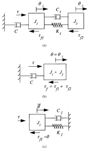
A stage mechanism for the servo system with friction effect was considered in this paper. For the 2-mass system in Fig. 1(a), let and represent the transmission compliance and the damping coefficient between the two lumped inertia, and . The driver exerts a commanded force at point , which is the system input, and is the position of which is the system output. There is a damper acting directly on the inertia , and and are the stick-slip frictions of
and , respectively. 1063–6536/99$10.00 1999 IEEE
(a)
(b)
(c)
Fig. 1. (a) Linear 2–mass system. (b) Macro dynamic mode model. (c) Micro dynamic mode model.
A. Macro Dynamic Mode
As described in Section I, when the applied force is strong enough to break the static friction, the servo system output does not restore to the original position, and the system is defined to be in a “macro dynamic mode.” The movement in this case is relatively large, and the compliance effect is negligible. The system can thus be treated as one lumped system as shown in Fig. 1(b), and the state equations can be written as
(1) where and are the position and velocity of the lumped
inertia, respectively, and
are system parameters, is the applied input, and represents the friction force.
In this mode of operation, Karnopp model [6] is sufficient to describe the friction force. Thus, the friction force can be described by
(2) where
for
for (3)
The stick friction, , in (2) is represented by for
for
for .
(4)
The positive and negative limits, and can be different.
The stick friction, , is in effect when and
the magnitude of the applied force is less than the stick force limits. The value of is set to be a small positive number only in the simulation to ensure that the numerical integration algorithm remains stable.
The slip friction is given by
(5) where is a step function. The function is the slip friction for positive velocities, and is the slip friction for negative velocities. and may not be equal. B. Micro Dynamic Mode
Before the lumped inertia commences macro motion, if the applied force is insufficient to overcome the stick friction, there is a small deflection caused by system compliance, and the deflection is almost proportional to the applied force [17]. This movement arises from two sources: a very small elastic deformation of the friction contacts, and a slight structural deformation. If the applied force is removed suddenly, the output will have a damped oscillation and finally resume the original position. Both movements are observed in the experiments. This mode of behavior is defined as the “micro dynamic mode.” The equivalent model of system is shown in Fig. 1(c). The inertia is treated as stationary during the
action and the friction is neglected. is the
damping coefficient, is the stiffness, and
is the output displacement, respectively. The dynamic behavior in this system can be represented by
(6)
where , , and , and
assuming that the deflection and velocity due to the compliance
effect are and where is the position of
the lumped inertia, and is the equilibrium point of the restoring mode.
III. CONTROLLER DESIGN
The position controller must ensure that the system response will ultimately reach and stay within a sufficiently small neighborhood of the zero state. In this paper, an extension of the robust nonlinear controller proposed in [18] and [19] will be derived to ensure uniform ultimate boundedness of the system trajectory. The uniform ultimate boundedness is achieved for both the macro and micro dynamic ranges. The experimental results in the following sections indicate that the controller is capable of controlling the system across the macro dynamic range and achieves microscopic control resolution. Since the trajectory converges according to the controller
specification, the size of the limiting set would define the control resolution.
A. State Equations
Define a set of unified state variables, , , , and system output, , for both the macro and micro-dynamic modes as
(7) (8)
(9) In (8), is an augmented state for integration control action,
and are the position and the velocity, respectively. The model for the macro mode dynamics in (1) can be described by a state equation of the form
(10) where
(11) and
(12) The model for the micro dynamic mode in (6) can be described by a state equation of the form
(13) where
(14)
For the macro-dynamic mode, the pair ( , ) in (10) is controllable. Therefore, an appropriate state feedback can
be found such that matrix is a Hurwitz matrix.
From Lyapunov stability theorem, there exists a symmetric positive definite matrix , such that the Lyapunov matrix equation
(15) has a corresponding unique solution for , and is positive definite.
B. The Robust Controller
The controller design is an extension to the robust controller in [17] with
(16) where
(17)
is the state feedback matrix such that is
Hurwitz, and
(18) where is the positive definite solution of the Lyapunov matrix equation, (15), and the scalar function is given by (19)
where , , and . The term is a design
parameter useful for overcoming the uncertain effect caused by friction uncertainty and mode uncertainty.
The complete model of the system contains great uncertainty because information about the friction, , and the switching between macro and the micro modes are not com-plete; it is only known that their structure is “cone bounded” as defined in the following assumptions.
Assumption 1: There exist finite positive constants, and , such that
(20) Assumption 2: There exists a finite positive constant , such that (21) as shown in (22)–(24) (22) (23) and (24) Consider ellipsoids constant (25)
one can define as the smallest ellipsoid containing
ball , where . is the smallest
ellipsoid containing ball , where . The
ellipsoids are ellipsoids with , and is the
Definition—Uniform Boundedness: Given a solution :
, , say of (10) and (13), it is
uniformly bounded if there is a positive constant , possibly dependent on but not on , such that
for all .
Definition—Uniform Ultimate Boundedness: Given a
solu-tion : , , it is uniformly
ultimately bounded with respect to set if there is a
nonneg-ative constant , possibly dependent on and
but not on , such that for all .
Select
(26) as a Lyapunov function for the closed-loop system.
Theorem 1: Under Assumption 1, the trajectories of the macro dynamic mode system in (10) subject to the controller (16) with (15), and in addition, with
(27)
is uniformly bounded with , and is ultimately
bounded with respect to , with for
for .
Proof: Select Lyapunov function (26) for the closed-loop system. The derivative of is given by
(28) Notice that
(29) subject to (15) and (20), one has
(30) where denotes the spectral radius.
From (30), there exists , such that ,
, with
(31) Let
and are defined in (27). With the argument in [19], one concludes the proof.
Theorem 2: Under Assumption 2, the trajectories of the micro dynamic mode system in (13) subject to controller (16) with (15), and in addition, with
(32)
is uniformly bounded with , and is ultimately
bounded with respect to , with for
for .
Proof: Select the same Lyapunov function (26) for the closed-loop system. The derivative of is given by
(33) Subject to (15), (21), (22), (24), and (30), one has
(34)
From (34), there exists , such that ,
where
(35) Let
and is defined in (27). Again, with the argument in [19], one concludes the proof.
From (31) and (35), smaller value of produces smaller
ellipsoids and . If one chooses to be
smaller than the most conservative micro dynamic region, the control system will enter the micro dynamic region in finite time. If one chooses to be small enough, then one achieves stable precision control with resolution bounded by .
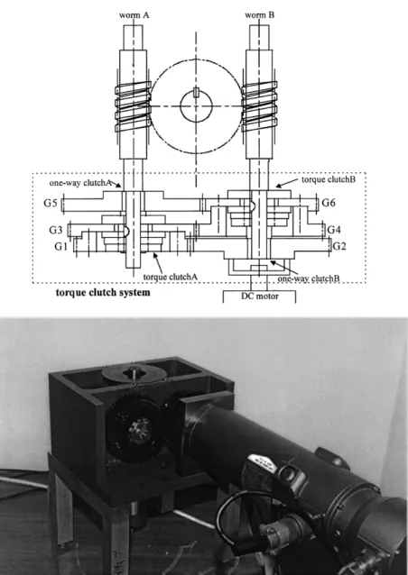
IV. EXPERIMENTALSETUP ANDSYSTEMIDENTIFICATION The test system as shown in Fig. 2 is referred to as a traction type drive device (TTDD) [19], [20]. The TTDD is an antibacklash twin worm index system. It is composed of two worms and a torque clutch system. The torque clutch system is combined with two one-way-clutches, two torque clutches and six gears to achieve a backlashless and self-retaining operation.
Fig. 2. Traction type drive device (TTDD).
The system can eliminate the backlash between the worm and the worm gear, and its basic structure is a rotational analogy of the system in Fig. 1. Due to its design, the backlash problem in the TTDD index can be neglected. However, friction becomes significant due to the torque clutch system.
Fig. 3 shows the experimental setup that consists of a TTDD index, a personal computer, a servomotor, the motor driver and a transducer for position measurement. The PC reads the pulses from the decoder and sends the torque command through the DAC to the DC motor driver that drives a BALDOR SD45-20-A1-A13 servo motor. The driver saturation is 1.24 N-m. The position measurement uses a Canon K.1 super high-resolution encoder. The encoder produces 81 000 sine-wave/rev and achieves arc-s resolution. The encoder measures the worm wheel angle.
Referring to Fig. 2. When the applied torque is strong enough the move the worm wheel, say in the counterclockwise direction. The worm wheel rotates, and one-way-clutch gets lock up to drive worm , and worm in turn drives the worm wheel to act as the load worm. In this case, worm
Fig. 3. Experiment setup.
is driven by the worm wheel and is the control worm. As the worm wheel undergoes clockwise rotation, worm and worm exchange roles. In both situations, the dynamic behavior can be treated with the macro dynamic mode model, and the state equations are shown in (1). System identification
(a)
(b)
Fig. 4. Experimental results for right triangular wave form response. (a) Force input. (b) Position output.
by fitting the acceleration response of the system with various torque commands shows that the system inertia is 3.635 10 m kg, and the viscous friction could be neglected. The
parameters in (1) are , and m kg , and
the parameters in the Karnopp model, (2)–(4), are
Nm (the stick friction), Nm (the slip friction
in the counterclockwise direction), Nm (the
slip friction in the clockwise direction), and the zero-region is rad/s.
In case when the applied torque is less than the stick friction, the situation is different. Suppose the applied torque is in the counterclockwise direction, worm is locked up by the torque clutch; however, worms and still undergo movements in the submicrometer range. The worm wheel will rotate only within arc-s depending on the bearing materials. If the applied torque is released, the output will oscillate and eventually restore to the original position. This phenomenon is similar to the Dahl effect, but with different mechanism. The Dahl effect is caused by the deflection of the bristles between the contact surfaces, while in this case the movements are caused by the deflection of the worms.
Figs. 4 and 5 show the experimental response of a right triangular wave input whose magnitude is less than the stick friction. It is seen that the dynamic behavior demonstrates clear second-order system characteristics. System identifica-tion based upon the ARMAX model shows that the parameters
in (6) are Nm/arc-s, s ,
s , and m kg . The simulation results based on
these parameters are also shown in Fig. 5.
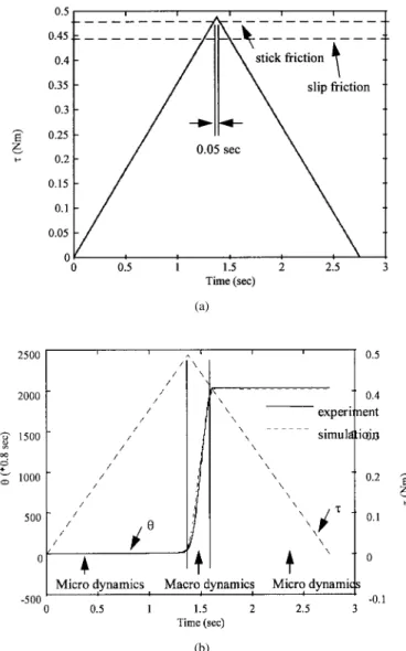
Fig. 6 shows the experimental response of a triangular shape force input with its peak exceeding the stick friction by about 0.02 Nm at duration of 0.05 s. Comparing Figs. 4 and 6, it can be seen that the deflection from the compliance effect is about 6 arc-s. However, Fig. 6 shows that the worm wheel moves about 1600 arc-s, exceeding the macro dynamic mode range
(a)
(b)
Fig. 5. Experimental and simulation results for right triangular wave form response. (a) Complete wave form response. (b) The detailed response.
and there is no oscillation. Therefore, it is adequate to say that the compliance effect is negligible under macro dynamic motion.
V. SIMULATION ANDEXPERIMENTAL RESULTS For comparison purpose, three kinds of controllers are in-troduced: the adaptive pulse width control (APWC) introduced in [12], the robust nonlinear stick-slip friction compensation (RNSFC) in [11], and the proportional and derivative (PD) controller [15]. The position command is 6 encoder pulses (6
0.8 4.8 arc-s).
APWC was proposed for a precise point-to-point positioning system in the presence of stiction and Coulomb friction. It is used when the motion stops short due to stiction and a positioning error remains. The control logic is based on single pulse inputs with the pulse width updated by an adaptation law. The pulse sequence continues until the motion comes to a stop with zero error. In this experiment, the pulse height is 0.566 N-m, and MRAC algorithm [12] is used. The experimental and simulation results are shown in Figs. 7(a) and 8(a), with the position response in Fig. 7 and the input response in Fig. 8.
(a)
(b)
Fig. 6. Experimental and simulation results for right triangular wave form response. (a) Force input. (b) Position output.
It is very difficult to bring the system response into a suitable range near the desired position.
A PD control is simple and easy to implement, and when applied to the system with friction, the state trajectories converge to the desired point with a bounded steady-state error. In order to make the desired point a unique equilibrium point, the RNSFC [11] method introduces an additional nonlinear compensation force so that the mass will move continuously toward the set point. The RNSFC is essentially a bang-bang force near the desired point. In this experiment
N-m/arc-s, N-m-s/arc-s, arc-s,
and arc-s are selected for the test system. The experimental and simulation results are shown in Figs. 7(b) and 8(b). Again, it seems that the closed-loop system becomes unstable in very high-resolution applications.
When a PD control is applied to the system under the influence of stick-slip friction, the radius of a set of multiple equilibrium points and the proportional gain are in inverse proportion. Thus, high feedback gains are not only good for the transient response but also useful for obtaining a smaller steady-state error. Unfortunately, high gains introduce
(a)
(b)
(c)
Fig. 7. The performances of different controllers. (a) The output of APWC. (b) The output of RNFSC. (c) The output of PD control.
stability problem from the system uncertainty and the digi-tal discretization implementation. In this case, to overcome the stick friction, the proportional gain must be larger than
0.117 N-m/arc-s, therefore, N-m/arc-s, and
N-m-s/arc-s are selected. The results are shown in Figs. 7(c) and 8(c). From the simulation results, it is seen that large proportional gain produces a small steady-state error. However, it is found to be unstable in the experiment when system uncertainty exists. After some trial and error, it was found that the proportional gain must be less than 8.84 10 N-m/arc-s in order to ensure response with no oscillations. Thus, PD controller alone can not satisfy the precision control specifications. From these results, it is found that the controllers all have stability problem because they are designed for the macro-scale stick-slip friction system without the micro-scale compliance effect.
Now lets turn to the proposed controller (16). Select poles
at 100 with 63 660, 2000, 127.3,
2, 0.5, and 10 . The fact that
means that the augmented state is not of concern. Since the controller is designed for positioning servo, is chosen to be larger than . The position commands are two, four, and six encoder pulses, respectively, and the results are shown in Fig. 9. Notably, the “step” behavior of the path is caused by the encoder resolution. As found in Fig. 9, an improved performance is obtained. The system reaches the desired target in about one second.
(a)
(b)
(c)
Fig. 8. The performances of different controllers. (a) The input of APWC. (b) The input of RNFSC. (c) The input of PD control.
(a)
(b)
Fig. 9. The performance of the proposed controller. (a) Position output. (b) Force input.
In addition, Fig. 10 shows the situation when the position command is set to 1000 pulses so that the system moves across the macro dynamic range. Select poles at 20 with
63 660, 2000, 127.3, 0.2, 0.05, and
10 in (16). It is seen that there is no overshoot observed and the control system achieves precision control with one encoder pulse accuracy within 1 s. The single controller is
(a)
(b)
(c)
Fig. 10. The performance of the proposed controller for long range seek (1000 pulses) command. (a) Position output. (b) Force input. (c) The detailed output of (a).
capable of moving the system across the macro dynamics range and achieves micro positioning accuracy with very good performance.
VI. CONCLUSIONS
A single robust controller is proposed in this paper for the control of a friction system with dual dynamic modes. The controller is shown to achieve uniform ultimate boundedness in both the micro and the macro dynamic ranges. Since there is only one controller, the system is capable to move across the macro dynamic range and settles with micro dynamics accuracy. Simulations and experiments are then carried out to examine the controller performance. Different controllers are compared. The results showed that the proposed controller is relatively simple to implement and its performance compares favorably over the other controllers.
REFERENCES
[1] D. A. Hassig and B. Friedland, “On the modeling and simulation of friction,” Trans. ASME J. Dynamic Syst., Measurement, Contr., vol. 113, pp. 354–362, 1991.
[2] D. Karnopp, “Computer simulation of stick-slip friction in mechanical dynamic systems,” Trans. ASME J. Dynamic Syst., Measurement, Contr., vol. 107, pp. 100–103, 1985.
[3] S. E. Mentzeloplou and B. Friedland, “Experimental evaluation of friction estimation and compensation techniques,” in 1994 Amer. Contr. Conf., Baltimore, MD, 1994, vol. 3, pp. 3132–3136.
[4] B. Armstrong, Control of Machines with Friction. Boston, MA: Kluwer, 1991.
[5] C. Canudas, H. Olsson, K. J. Astrom, and P. Lischinsky, “A new model for control of systems with friction,” IEEE Trans. Automat. Contr., vol. 40, no. 3, pp. 419–425, 1995.
[6] S. M. Phillips and K. R. Ballou, “Friction modeling and compensation for an industrial robot,” J. Robot. Syst., vol. 10, no. 7, pp. 947–971, 1993.
[7] Y. Yoshida and M. Tanaka, “Position control of a flexible arm using a dither signal,” JSME Int. J., Series C, vol. 36, no. 1, 1993.
[8] S. Cetinkunt, W. L. Yu, and A. Donmez, “Friction characterization experiments on a single point diamond turning machine tool,” Int. J. Mach. Tools Manufact., vol. 34, no. 1, pp. 19–32, 1994.
[9] E. D. Tung and M. Tomizuka, “Feedforward tracking controller design based on the identification of low frequency dynamics,” Trans. ASME, vol. 115, Sept. 1993.
[10] L. Guzzella and A. H. Glattfelder, “Positioning of stick-slip systems-comparison of a conventional and a variable-structure controller design,” in Proc. 1992 ACC, 1992, vol. Wp13, pp. 1277–1281.
[11] S. C. Southward, C. J. Radcliffe, and C. T. MacCluer, “Robust non-linear stick-slip friction compensation,” Trans. ASME J. Dynamic Syst., Measurement, Contr., vol. 113, pp. 639–645, Dec. 1991.
[12] S. Yang and M. Tomizuka, “Adaptive pulse width control for precise positioning under the influence of stiction and Coulomb friction,” Trans. ASME J. Dynam. Syst., Measurement, Contr., vol. 110, pp. 221–227, Sept. 1988.
[13] C. Canudas, “Robust control for servo-mechanisms under inexact fric-tion compensafric-tion,” Automatica, vol. 29, no. 3, pp. 757–761, 1993. [14] C. Canudas, K. J. Astrom, and K. Braun, “Adaptive friction
compen-sation in DC motor drives,” IEEE J. Robot. Automat., vol. RA-3, pp. 681–685, Dec. 1987.
[15] P. E. Dupont, “Avoiding stick-slip through PD control,” IEEE Trans. Automat. Contr., vol. 39, May 1994.
[16] S. J. Huang, J. Y. Yen, and S. S. Lu, “Stability of PDF controller with stick-slip friction drive device,” Trans. ASME J. Dynamic Syst., Measurement, Contr., vol. 119, pp. 486–490, 1997.
[17] P. I. Ro and P. I. Hubbel, “Model reference adaptive control of dual-mode micro/macro dynamics of ball screws for nanometer motion,” Trans. ASME J. Dynamic Syst., Measurement, Contr., vol. 115, pp. 103–108, 1993.
[18] M. J. Corless and G. Leitmann, “Continuous state feedback guaranteeing uniform ultimate boundedness for uncertain dynamic systems,” IEEE Trans. Automat. Contr., vol. AC-26, pp. 1139–1144, Oct. 1981. [19] G. Leitmann, “On the efficacy of nonlinear control in uncertain linear
systems,” ASME J. Dynamic Syst., Measurement, Contr., vol. 102, pp. 95–102, June 1981.
[20] T. H. Yang, “Double acting type dynamic back spacing removed driving system,” U.S. Patent 5 265 488, 1993.
[21] S. J. Huang, J. Y. Yen, and S. S. Lu, “A new compensator for servo systems with position dependent friction,” Trans. ASME J. Dynamic Syst., Measurement, Contr., 1995.
[22] S. J. Huang, J. Y. Yen, C. C. Ou, and S. S. Lu, “Combination of TTDD and PDF control for backlashless operation” Bull. College Eng., NTU, no. 66, pp. 1–11, Feb. 1996.
Shi-Jung Huang was born in Changhua, Taiwan.
He received the B.S. degree from National Chunghsin University, Taiwan, in 1990. He received the M.S. and Ph.D. degrees from National Taiwan University, Taiwan, in 1992 and 1997, respectively. He is currently serving as a Second Lieutenant in the Chinese army. His main research interests lie in the areas of servo control for high precision position systems and servo design for machine tool systems.
Jia-Yush Yen (M’87) was born in Taipei, Taiwan.
He received the B.S. degree in power mechani-cal engineering from National Tsinghua University, Hsinchu, Taiwan, in 1980, and the M.S. degree from the University of Minnesota, Minneapolis, in 1983. In 1989, he received the Ph.D. degree in mechanical engineering from the University of California, Berkeley.
During his study at Berkeley, he received the IBM Graduate Fellowship in 1984–1985. Since 1989, he has been with National Taiwan University, Taipei, Taiwan, where he is currently a Professor of Mechanical Engineering. His research interests are in the areas of modeling and control of electromechanical systems, especially in precision control of computer peripherals and precision measurement systems.
Dr. Yen served as the treasurer of the Control System Chapter in the IEEE Taipei Section in 1992. He also served as consultant for many companies including the Industrial Technology Research Institute, Taiwan, and C Sun MFG. LTD., Taiwan. He is a member of the ASME.
Shui-Shong Lu received the B.S. degree from the
Department of Mechanical Engineering at National Taiwan University in 1965. He obtained the M.S. degree from the Department of Mechanical and Aerospace Engineering at the University of Michi-gan in 1972.
He has been with the Department of Mechanical Engineering at National Taiwan University since 1975. His major research interests are in manufac-turing automation and machine tool control.