國立交通大學
光電工程學系碩士班
碩士論文
短硫鏈分子對殼核硒化鎘/硫化鋅量子點光學性
質之研究
The Effect of Short-Chain Thiol Capping Layer on Optical
Properties of CdSe/ZnS Quantum Dot
研究生 : 許安佳
指導教授 : 安惠榮 教授
短硫鏈分子對殼核硒化鎘/硫化鋅量子點光學性質之研究
The Effect of Short-Chain Thiol Capping Layer on Optical
Properties of CdSe/ZnS Quantum Dot
研究生 : 許安佳 Student : An-Chia Hsu
指導教授 : 安惠榮 教授 Advisor : Prof.
Hyeyoung Ahn
國立交通大學
光電工程學系碩士班
碩士論文
A Thesis
Submitted to Department of Photonics and Institute of Electro-Optical Engineering
College of Electrical Engineering National Chiao Tung University in partial Fulfillment of the Requirements
for the Degree of Master of Science
in
Institute of Electro-Optical Engineering June 2012
Hsinchu, Taiwan, Republic of China
I
The Effect of Short-Chain Thiol Capping Layer on Optical Properties of
CdSe/ZnS Quantum Dot
Student: An-Chia Hsu Advisor: Dr.
Hyeyoung Ahn
Institute of Electro-Optical Engineering
National Chiao Tung University
ABSTRACT
The optical property analysis of short-chain thiol-containing molecules capping on CdSe/ZnS quantum dots (QDs) is reported. The electronic and optical properties of QDs are closely related with the highly surface-to-volume ratio and their surface electronic structure. Here we used core/shell QDs with some thiol molecules including β-Mercaptoethanol(BME), 3-Mercaptopropionic acid (MPA), and 1-propanethiol(NPM) to examine the effect of QD surface-thiol interaction of defect sites in short (immediately) and long (24 hr.) aging time. A comprehensive study of ultrafast spectroscopy, up conversion fluorescence, and temperature-dependent photoluminescence was used to clarify the function of thiols on QDs surface. We found the thiol molecules interact with QD only by weak coordination-type bonds through the sulfur lone-pair electrons. The thiol molecules can passivate the surface of QDs by preventing core electron from defect sites on the surface thus enhance PL intensity. While the strong covalent-type bonds are formed as thiol turn to thiolate through the long time incubation, new hole traps would be produced thus PL intensity quench. Thiol-containing molecules under investigation show different performance, which attribute to anti-oxidation, dissociation ability and second-order oxygen of the thiols.
II
Finally, we found that the surface passivation occurs as long as the QDs are surrounded with negative charges since thiol-/-dithiol molecules have sulfur lone-pair electrons. That is the main reason why thiol-molecules usually apply to exchange ligands on the QDs surface.
III
短硫鏈分子對殼核硒化鎘/硫化鋅量子點光學性質之研究
研究生 : 許安佳 指導教授 : 安惠榮博士
光電工程學系碩士班
國立交通大學
摘要
本論文主要藉由由光譜及光學量測,討論含硫基的短硫鏈分子對殼核硒化 鎘/硫化鋅量子點表面的影響和效用。由於量子點的表面對體積的比例極高,因 此量子點的表面電子分佈結構會決定其物理性質及光學性質。此篇論文,我們使 用一些硫醇分子,包括 β-巰基乙醇 (BME) ,3 - 巰基丙酸(MPA)和 1 - 丙硫醇(NPM)去測試分子和殼核量子點表面缺陷的交互作用。其中分成兩個 研究的時間點 : 加入硫醇分子立即量測,以及加入分子後,過 24 小時再量測。 我們主要只用超快吸收光譜、上轉換螢光光譜、溫度相關光致發光光譜和穩態螢 光光譜來釐清硫醇分子對量子點的作用和機制。由實驗結果,可以知道硫醇分子 (thiol) 先由硫基孤對電子對 (sulfur lone-pair) 靠近量子點表面,以微弱的配位鍵 形式 (coordination-type) 靠在量子點表面並減少表面缺陷,使量子點的表面鈍化 (surface passivation),螢光強度增強 (PL enhancement) . 長時間後,硫醇分子會 轉為硫醇基(thiolate),分子改由較強的共價鍵形式 (covalent-type) 鍵結在量子點 表面,但同時也產生新的缺陷,致使電洞由核內轉移出來,使螢光減弱 (PL quench)。此篇使用的硫醇分子對量子點有不同的影響,可能是抗氧化力、硫醇 分子解離能力,或者是否有其餘孤對電子對作用等因素。最後,我們發現只要量 子點表面附近有足夠的電子雲,就能使量子點表面鈍化。這是硫醇分子常被用來 進行量子點配位體交換 (ligand exchange) 的主要原因。
IV
Acknowledgement
這兩年碩士班匆匆就這樣過去了,剛進實驗室,連雷射工作原理都不懂,到 現在架光路、找訊號、配樣品,樣樣輕鬆自如。這樣的成果,不斷失敗、再努力 才能做到的。這兩年,湯朝暉老師提供了良好的實驗環境和資源、充分的自由度, 讓我可以隨心所欲進行感興趣的實驗。安惠榮老師在每周一次的會議上,一次又 一次的修正我的研究方向。於平博士手把手帶領我做實驗,鉅細靡遺的將他的專 業知識、經驗傳授給我,為我找到研究的方向。他們是我能順利完成研究畢業的 最大功臣,真的非常感激。實驗室人才濟濟,文小明博士對各種光學系統都有深 厚了解,扮演了我最好的求救對象;院繼祖博士研究量子點多年,每每有相關問 題就會向他請教;鄭信民博士和李弘貿博士熟悉半導體材料合成相關技術,和他 們討論獲益良多。戴伯澤博士和我只短短相處 4 個月,但卻帶領我走入超快雷射 領域,教導我其基本知識。期望這些給予我幫助的博士後們,能在未來找到一份 心儀的研究工作。熱血的國晏、可愛的維尼,兩位學長常常陪我做實驗,老是麻 煩你們我也很不好意思,還是只能一句感謝。高音頻昀睿、布丁狗賢真、帥氣黃 婕、籃球姐 Fish,你們的陪伴讓實驗室的氣氛輕鬆自在,充滿了笑聲。安老師 實驗室的誌彰、賈哥、小至、晏銘學長撐起了碩一時的會議,讓我愉快的度過碩 一的歡樂時光。陪伴了我兩年的好夥伴們:美麗的紀瑩、誠懇的育昇、幽默的東 東,和我一起度過修課、做實驗、會議上被責備的日子,謝謝,也祝福你們未來 都有光明的前程。夏天火氣大的宇傑、重訓室魔人的厚升、安老師實驗室的珉澤、 邦賢、修禾、可揚,實驗室就交給你們囉!希望你們的實驗也都能順利。當然, 一定要感謝我的家人,這兩年是你們的支持和鼓勵,我才能完成我的碩士學位。 在我鬧脾氣、耍任性時,你們的關懷和包容,現在回想起來真的很感動。最後, 謹將這篇論文獻給我的父母,生養我、栽培我,是我心靈上和經濟上的支柱。謝 謝你們。V
Table of Contents
ABSTRACT ... I
Acknowledgement ... IV
Table of Contents ... V
List of Tables ... VII
List of Figures ... VIII
Chapter 1 Introduction ... 1
1-1 Semiconductor Quantum Dots ... 1
1-2 Motivation and literature review ... 3
1-3 Layout of thesis ... 9
Chapter 2 Semiconductor Quantum Dots (QDs) and Organic
molecules ... 11
2-1 Quantum confinement in Semiconductor QDs ... 11
2-2 Structure properties of QDs ... 15
2-2.1 Surface of QDs ... 15
2-2.2 Shell passivation ... 17
2-3 Optical properties of QDs ... 19
2-4 Organic molecules ... 22
Chapter 3 Experiment methods and Apparatus ... 23
3-1 Transient absorption two color pump-probe measurement ... 23
3-1.1 Wavelength tunability and optical parametric amplifiers . 25
3-1.2 Experimental system of pump probe setup ... 28
3-2 Temperature dependent PL measurement ... 30
3-3 Sample preparing ... 33
VI
4-1 Transient absorption ... 35
4-2 Steady-state fluorescence ... 39
4-3 Time resolved photoluminescence ... 43
4-4 Temperature dependent fluorescence ... 45
4-4-1 Fluorescence intensity ... 45
4-4-2 Energy gap variation ... 51
4-4-3 Band width of fluorescence ... 58
Chapter 5 Recommendation for Further Work and Summary ... 62
5-1 Electronic coupling in CdSe/CdS film ... 62
5-2 Summary... 67
VII
List of Tables
Table 2-1. Showing the thiols under investigation with chemical formula
and pK
a. ... 22
Table 4-1. Show the double exponential function fitting parameters of
Figure 4-2. The last row indicates the average decay
lifetime. ... 38
Table 4-2. Shows the activation energy of QDs and with thiols extracted
from fluorescence intensity fitting curve in figure 4-7. ... 50
Table 4-3. Fit parameters of the energy gap variation in QDs temperature
dependent fluorescence measurement. It was fit using
equation 4-6. ... 55
Table 4-4. Parameters used in the fit of the photoluminescence FWHM
as a function of temperature by equation 4-7 ... 61
Table 5-1. The peak position and band width of pure QDs and DTT
VIII
List of Figures
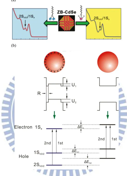
Figure 1-1.Ou Chen et al. exhibit surface-functionalization-dependent
excitonic absorption (a) Show that the transition energy and
extinction coefficient of the E
2(2S
h3/21S
e) excitonic band of
these nanocrystals can be strongly modified by their surface
ligands as well as ligand-associated surface atomic arrangement.
(b) Scheme of ligand effects on the electronic structure of a
CdSe Nanocrystal [4]. ... 2
Figure 1-2. (a) Typical intensity time trace of CdSe/ZnS single-molecule
QDs in TN buffer (upper panel) and in BME solution (lower
panel). (b) Showing blinking behavior of single-molecule QDs
reverse immediately as different solution delivered via a flow
system [12]. ... 4
Figure 1-3. (a) Effect of BME concentration and time on PL QYs of
CdSe/ZnS QDs in pH-neutral conditions. QDs concentration
is 0.02 μM, with BME maximum 8 order higher than it [11].
... 5
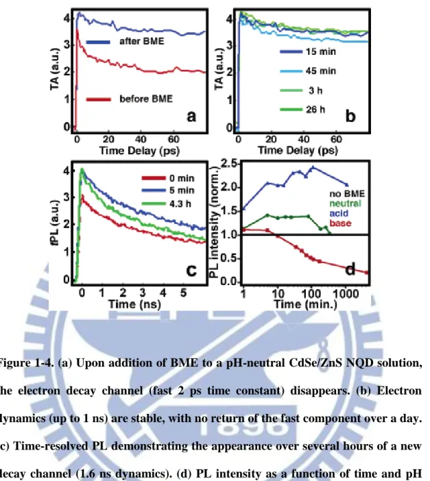
Figure 1-4. (a) Upon addition of BME to a pH-neutral CdSe/ZnS NQD
solution, the electron decay channel (fast 2 ps time constant)
disappears. (b) Electron dynamics (up to 1 ns) are stable,
with no return of the fast component over a day. (c)
Time-resolved PL demonstrating the appearance over
several hours of a new decay channel (1.6 ns dynamics). (d)
PL intensity as a function of time and pH [11]. ... 6
IX
pH values with different BME concentrations. The top two
plots measured immediately after BME addition (A) at pH
=7, (B) at pH = 9. The middle plots measured 4 hr
incubation (C) at pH = 7, (D) at pH = 9. (E) QDs solubilized
with BME compared with MPA QDs alone. (F) Samples
deaerated with nitrogen flush [13] . ... 8
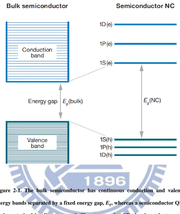
Figure 2-1. The bulk semiconductor has continuous conduction and
valence energy bands separated by a fixed energy gap, E
g,
whereas a semiconductor QDs is characterized by discrete
atomic-like states and a QD size-dependent energy gap. The
QD energy structures are shown for the model case of a
two-band semiconductor, which has a single parabolic
conduction band and a single parabolic valence band [19].
... 13
Figure 2-2. (a) Tunability of QDs nanocrystal. (b) Absorption and
emission spectra of four CdSe/ZnS QDs. The blue line
indicates the 488nm line of an argon ion laser, which can be
used to efficiently excite all four types of QDs
simultaneously. (c) The colorful PL spectrum [17, 18]. ... 14
Figure 2-3. Showing the absorption and fluorescence spectra for
electron-rich and cation-rich QDs situation [21]. ... 16
Figure 2-4. Chemical structure of the CdSe semiconductor QDs (a)
Bare CdSe QDs. (b) Core/shell QDs surrounded by ZnS or
CdS. (c) Commercial CdSe/ZnS core/shell QDs further
coated with polymer. ... 18
X
Figure 2-5. Schematic diagrams showing on/off light emission
(blinking) in core/shell QDs (upper), and suppression of
blinking in giant-shell and gradient alloy nanocrystals
(lower). ... 21
Figure 2-6. Explain the blinking phenomena which is based on
non-radiative Auger process. ... 21
Figure 3-1. The simplified diagram to produce SHG and THG. The
first nonlinear crystal produce SHG signal (400nm), and
interacted with fundamental pulse in the second nonlinear
crystal, reproducing THG signal (266nm). Dichroic mirrors
are added to extract the specified frequency. ... 25
Figure 3-2. Principle of OPA for extending the wavelengths through
nonlinear interaction. ... 27
Figure 3-3. (a) Two color transient absorption pump-probe
measurement setup. (b) The real photo of pump-probe setup.
... 29
Figure 3-4. (a) Simply show the temperature dependent fluorescence
experimental setup. (b) The real photo of the system. ... 32
Figure 3-5. (a) The absorption and (b) the fluorescence spectra of
CdSe/ZnS core/shell QDs used in this study. The B1 feature
(first absorption peak) is around 550nm and the PL peak is
around 565nm at room temperature. ... 34
Figure 4-1. Transient absorption traces at the 1P
eto 1S
efor the
CdSe/ZnS QDs in aqueous phase taken with different pump
laser powers (shown in the figure). ... 37
XI
Figure 4-2. Transient absorption spectra for CdSe/ZnS QDs with
different short chain thiol-containing molecules at 24 hours
aged. ... 38
Figure 4-3. Steady-state fluorescence spectra of CdSe/ZnS QD with
three different BME/QD molar concentration ratios vs. time.
... 41
Figure 4-4. Steady-state fluorescence spectra of CdSe/ZnS QD with
three short chain thiols (5 order concentration ratios) vs.
time. ... 42
Figure 4-5. Time-resolved photoluminescence spectra of CdSe/ZnS QD
with three different BME/QD molar concentrations ratios
and measured immediately and 24 hr incubation. ... 44
Figure 4-6. The first plot is the temperature dependent fluorescence of
pure QDs. The lower 6 figures show the PL with short chain
thiols: BME, MPA, and NPM at 10 min and 24 hours at left
and right side, respectively. ... 47
Figure 4-7. Arrhenius plot of fluorescence intensity for the edge-band
of QDs with thiols. Evidently, pure QDs (black line) and
BME, MPA, and NPM with 10 min and 24 hours (color line)
incubation have large variation. ... 49
Figure 4-8. The energy gap extracted from PL curve fitted with single
Gaussian as a function of temperature. All thiols: (a) BME
(b) MPA (NPM) measured for immediately and 24 hr.
incubation ... 53
XII
QCSE separates the electron and hole wave functions and
therefore decreases the first exciton energy (red shift). ... 56
Figure 4-9(b). Scheme of surface ligand induced hole transferred and
trapped on the surface as covalent-type bonds was formed.
Therefore, electron and hole separate and the energy gap
red shift as case one. ... 57
Figure 4-10. FWHM bandwidth (dots) as a function of temperature
and fit by equation 4-7 (solid lines) of QDs with (a)
BME-capped (b) MPA-capped (c) NPM-capped. ... 60
Figure 5-1. Showing the formula of dithiothreitol (DTT). ... 63
Figure 5-2. Absorbance of liquid (solid line) and solid (dotted line) for
CdSe/CdS QDs (E
g= 2.35eV) in citrate (black) and in DTT
(blue). ... 64
Figure 5-3. The schematic diagram shows a dithol molecule DTT
connect to two QDs enhanced QDs coupling. ... 65
Figure 5-4. (a)Transient absorption spectra at low pump intensity
<N
abs= 0.5> and various probe wavelengths near the 1S
h-
1S
etransition for a QD / DTT film. (b) Contour plot of the
same data for the QD / DTT film. The black line in (b)
denotes the ground state absorption maximum. ... 66
Figure 5-5. Schematic diagram of thiols and QD surface interaction.
... 68
Figure 5-6. Schematic diagram of QDs surrounded by sulfur
lone-pairs and suppress blinking by preventing core
electrons eject to the defect sites of surface. ... 69
1
Chapter 1 Introduction
1-1 Semiconductor Quantum Dots
Colloidal semiconductor nanocrystals (NCs) or quantum dots (QDs) possess superior luminescence properties, high oscillator strength, photostability, broad absorption and narrow emission spectra, and thus attract a lot of research attention as promising materials for various application including bio-imaging, bio-labeling and coding, FRET-based sensors, and as for microscopy, nanophotonics, and optoelectronic devices [1]. A substantial amount of work has focused on the measurement of properties in CdSe/ZnS core shell QDs, primarily due to the relative ease in synthesizing sample (well developed for II-VI NCs) in the strong confinement regime ( r < αB = 5.6nm ) with narrow size dispersion and increased absorption
coefficient [2].
However, the restrict size of QDs cause large surface-to-volume ratio dictates their electronic and optical properties are dominated by the surface electronic structure, particularly band-gap electronic states [3]. Defects on the QDs surface such as unpassivated dangling bonds, adatoms, kinks, and vacancies often form shallow or deep trap states of electrons or holes make broad electronic states. These dominate their optical characteristics such as quantum yields (QY), photobleaching, blinking behaviors and Auger recombination. To date, a number of methods have been developed to passivate and control the surface of colloidal QDs. The surface modification can control the surface defects, micro-structural morphology and surface electronic density distribution for optimization of optical properties [4, 5]. Thus, an appropriate chemical treatment of the QD surface can have extensive application. For example, slowing down the electron cooling rate by capping ligands exchange is important for the solar cell application [6-9].
2
(a)
(b)
Figure 1-1.Ou Chen et al. exhibit surface-functionalization-dependent excitonic absorption (a) Show that the transition energy and extinction coefficient of the E2
(2Sh3/21Se) excitonic band of these nanocrystals can be strongly modified by their
surface ligands as well as ligand-associated surface atomic arrangement. (b) Scheme of ligand effects on the electronic structure of a CdSe Nanocrystal [4].
3
1-2 Motivation and literature review
Capping by the polymers or inorganic shell layers with higher band gap or molecule/atomic ligands exchange has been proved to be effective method for surface passivation and further confinement of charged carriers, therefore leading to a high luminescence efficiency [10, 11]. Thiol molecules are widely used in surface modification of QDs as well as metallic nanoparticles. Also, the optical properties of QDs are usually altered after the transform from thiol to thiolate whose chain lengths are relatively short. However, this process is complex and material dependent and has not been fully elucidated. Thiol-contained small molecules, beta-mercaptoethanol (BME), flush in pH-neutral aqueous solution can nearly completely suppress the blinking of single CdSe/ZnS QD was first discovered by Taekjip Ha and coworkers [12]. They have concluded these short chain thiols are highly dependent on the concentration, rather than number of thiol groups per molecule. It is surprising that the BME does not permanently change to show the quantum dot properties because the blinking behavior reappears immediately after replacing the buffer shown in Figure 1-2. The response attributed to thiol moiety, a potent electron donor, that could donate electrons to the surface electron traps renders them incapable of accepting electrons from the dot.
4
Figure 1-2. (a) Typical intensity time trace of CdSe/ZnS single-molecule QDs in TN buffer (upper panel) and in BME solution (lower panel). (b) Showing blinking behavior of single-molecule QDs reverse immediately as different solution delivered via a flow system [12].
5
Besides, Klimov et al. studied the PL efficiency and carrier dynamics as functions of thiol concentration, aging time, and pH to confirm the effect of thiols on QDs photophysics [11]. The continuous wave (CW) PL was used to characterize QYs shown in Figure 1-3, as a combination of time-resolved transient-absorption (TA) in 1Se and PL (t-PL) measurements, was used to monitor dynamics of photoexcited
electrons and holes shown in Figure 1-4. Where the TA is only sensitive to changes in electron dynamics and t-PL is sensitive to both electron and hole dynamics. They found the thiol (in pH-neutral and acidic conditions) can provide surface passivation of QDs and enhance their quantum yields, while the thiolate (in basic conditions) plays as the hole traps and quench the PL. As Ha’s work, it demonstrates strong concentration dependence.
Figure 1-3. (a) Effect of BME concentration and time on PL QYs of CdSe/ZnS QDs in pH-neutral conditions. QDs concentration is 0.02 μM, with BME maximum 8 order higher than it [11].
6
Figure 1-4. (a) Upon addition of BME to a pH-neutral CdSe/ZnS NQD solution, the electron decay channel (fast 2 ps time constant) disappears. (b) Electron dynamics (up to 1 ns) are stable, with no return of the fast component over a day. (c) Time-resolved PL demonstrating the appearance over several hours of a new decay channel (1.6 ns dynamics). (d) PL intensity as a function of time and pH [11].
7
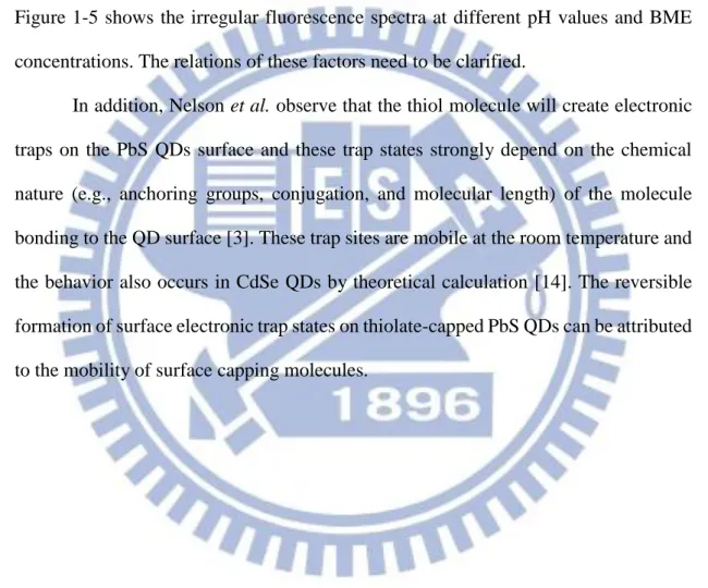
Recently, the higher concentrations of BME will increase the radiative recombination lifetime in QDs due to elimination of oxygen in solution has been demonstrated by Nadeau et al. [13]. The luminescence lifetime decays were measured by time-correlated single photon counting (TCSPS) and fit to a model of radiative recombination and trapping. It confirms the BME antioxidant effects and the complicated processes involved concentration, pH, aging time, and QDs materials. Figure 1-5 shows the irregular fluorescence spectra at different pH values and BME concentrations. The relations of these factors need to be clarified.
In addition, Nelson et al. observe that the thiol molecule will create electronic traps on the PbS QDs surface and these trap states strongly depend on the chemical nature (e.g., anchoring groups, conjugation, and molecular length) of the molecule bonding to the QD surface [3]. These trap sites are mobile at the room temperature and the behavior also occurs in CdSe QDs by theoretical calculation [14]. The reversible formation of surface electronic trap states on thiolate-capped PbS QDs can be attributed to the mobility of surface capping molecules.
8
Figure 1-5. Steady-state emission spectrum for CdTe QDs at different pH values with different BME concentrations. The top two plots measured immediately after BME addition (A) at pH =7, (B) at pH = 9. The middle plots measured 4 hr incubation (C) at pH = 7, (D) at pH = 9. (E) QDs solubilized with BME compared with MPA QDs alone. (F) Samples deaerated with nitrogen flush [13] .
9
1-3 Layout of thesis
The surface-dependent optical properties of colloidal quantum dots have been extensively studied in the past two decades. This advance has led to the preparation of a variety of high-quality colloidal nanocrystals with composition of II-VI, III-VI, and IV-VI semiconductors. The CdSe/ZnS core/shell colloidal QDs under investigation were purchased from Invitrogen Canada Inc. To our best knowledge, the QDs were widely used in many single-particle experiments and the function of short chain thiol-containing molecules yet to be clarified. So far, there is no ensemble ultrafast spectroscopy and temperature dependent PL data combined to understand the effect of surface ligand on structure and optical properties of QDs. Ultrafast spectroscopy provides a suitable means to investigate dynamical processes. Temperature dependent fluorescence experiments further study the surface modification influence including band gap, surface trap site and activation energy.
In this study, we used QD sample with different thiol-containing molecules to examine the effect of QD surface-thiol interaction on defect sites immediately and long aging time (24 hours). The thesis is organized as follows. The first chapter is a briefly introduction to colloidal semiconductor quantum dots (QDs) and related research review carrying on the motivation of this study. Chapter 2 presents a basic knowledge of semiconductor quantum dots structures and optical properties. The thiol-containing short chain molecules used in this study were also depicted in this chapter.
The description of the measurement system including transient absorption pump-probe technique and temperature dependent system setup are described in Chapter 3. We discuss the fundamental principles and the detailed experimental setups and sample used in our experiments. Besides, the real photos of these experiment systems were also shown in this chapter.
10
CdSe/ZnS core/shell quantum dots with short chain thiol molecules. We applied up-conversion photoluminescence and pump-probe transient absorption to detect the carrier dynamics on various time scales and discuss the physical meaning of the spectroscopy. The results were also confirmed by temperature dependent PL experiments. To identify the variety of thiol-molecules and QDs interaction, the steady state fluorescence vs. time was used. A summary and suggestions for future work were briefly described in chapter 5.
11
Chapter 2 Semiconductor Quantum Dots (QDs) and Organic
molecules
2-1 Quantum confinement in Semiconductor QDs
Usually, a natural length scale of electronic excitations in macroscopic, bulk semiconductors is given by the exciton Bohr radius, αB, which is determined by the
strength of the electron-hole (e-h) Coulomb interaction. In ultrasmall NCs with sizes comparable with or smaller than αB, the dimensions of the nanoparticle but not the
strength of the e-h Coulomb coupling define the spatial extent of the e-h pair state and hence the size of the NC exciton.The quantum dots (QDs), one of the central materials in nanoscience, is a semiconductor crystal with a physical size in the nano-order scale (~1-10 nm). The size of semiconductor QDs must within the Bohr radius. It is often called an “artificial atom” because researchers can create nanostructures which yield properties similar to those of real atoms. The key feature of these inorganic materials is that they are physically intermediate between the limit of molecules and bulk solid. Being in this regime, the quantum dot is one of the canonical systems of nanoscience [15]. At nanoscale dimensions, the normal collective electronic properties of the solid become severely disordered and the electrons tend to follow “particle in a box” model, to account for approximated band structure. It represents a class of quasi-zero-dimensional objects in which carrier motion is restricted in all three directions. Bulk crystalline structure is preserved in NCs; however, due to three-dimensional (3D) quantum confinement NCs have atomic-like discrete energy spectra that are strongly size dependent [16]. If a QD is irradiated by light with photon energy (hν) higher than bandgap (Eg), an electron will be excited from valence band to
conduction band. The bound state of the electron-hole pair is called an “exciton”, which can be used to study the relationship between the particle size and bandgap
12
energy of QDs. Equation 2-1 shows the dimension of particles decreases as the energy increases. By using the quantum confinement effects, it is possible to tune the energy bandgap. Therefore, the emission color could be changed over the whole visible range by varying the QD size, as shown in Figure 2-2(a) [17]. Moreover, the QD emission spectrum is symmetric in line shape and narrow in peak width. The absorption of QDs has an increase in probability at higher energies and a broadband and continuous absorption spectrum as presented in Figure 2-2 (b) [18].
Eq. (2-1)
Where Eg, QDs and Eg, b are the bandgap energies of the bulk solid and quantum dot,
respectively. R is the radius of QDs, me is the effective mass of the electron in the solid,
еis elementary charge of the electron, h is Planck’s constant, the mh is the effective
13
Figure 2-1. The bulk semiconductor has continuous conduction and valence energy bands separated by a fixed energy gap, Eg, whereas a semiconductor QDs is characterized by discrete atomic-like states and a QD size-dependent energy gap. The QD energy structures are shown for the model case of a two-band semiconductor, which has a single parabolic conduction band and a single parabolic valence band [19].
14
(c)
Figure 2-2. (a) Tunability of QDs nanocrystal. (b) Absorption and emission spectra of four CdSe/ZnS QDs. The blue line indicates the 488nm line of an argon ion laser, which can be used to efficiently excite all four types of QDs simultaneously. (c) The colorful PL spectrum [17, 18].
15
2-2 Structure properties of QDs
2-2.1 Surface of QDs
The dependence of optical properties on particle size is largely a result of the internal structure of the nanocrystal. However, as the crystal get much smaller like quantum dots, the number of atoms on the surface increases, which can also impact the optical properties. The atoms on the surface of a crystal facet are incompletely bonded within the crystal lattice, thus disrupting the crystalline periodicity and leaving one or more “dangling orbital” on each atom pointed outward from the crystal. If these surface energy states are within the QDs bandgap, they can trap charge carriers at the surface, thereby reducing the overlap between the electron and hole, increasing the probability of nonradiative decay events. In fact, most semiconductor QDs are suspended in solution and covered with organic ligands. Thereby, the dangling bonds on the exposed facets are “passivated” by bonding with atoms or molecules, minimizing intra bandgap surface states and reducing surface atomic reconstruction. For colloidal QDs suspensions, molecules with polar end groups and hydrophilic polymers could absorb to positively charged QDs by their negatively charged properties [20].
The surface trap state could significantly modulate the fluorescence. The colloidal QDs often show two fluorescence emission bands: one at the band edge and another at lower energy resulting from recombination at intra band gap defect sites on the surface. Figure 2-3 demonstrates the surface properties dependent fluorescence [21]. The existence of trap states of QDs may lead to low fluorescence quantum yield, broad fluorescence, and blinking because of charge recombination pathway. In addition, defects on the surface of QDs functioned as temporary surface traps for an electron or hole, which can result in nonradiative relaxation and reduce quantum yield [17].
16
Figure 2-3. Showing the absorption and fluorescence spectra for electron-rich and cation-rich QDs situation [21].
17
2-2.2 Shell passivation
For practical light-emitting applications, it is advantageous to coat semiconductor QDs with a shell in order to stabilize and maximize fluorescence. This not only passivates the surface bonds but also buries the semiconductor in a potential energy well, concentrating the charge carriers in the nanocrystal core, away from the surface [15, 17, 22]. Thereby, surface defect states and trap sites will have a diminished impact on the fluorescence efficiency and fewer environmental factors will influence the emission intensity. For colloid QDs, the normal progress of capping a shell to surround CdSe QDs is CdSe/CdS or CdSe/ZnS core/shell structure so that have efficient and stable fluorescence. Wider band gap CdS and ZnS shells not only electronically insulate the cores, but S2- has a much lower oxidation potential than Se2-, resulting in a higher threshold to photooxidative degradation and surface defect formation.
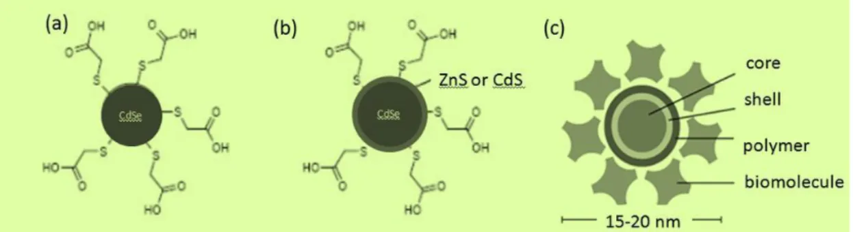
Recently, commercially available QDs are further coated with proprietary polymer and protein layers to render them biologically compatible. The compositions of three commonly used QDs are compared in Figure 2-4[invitrogen.com]. For bare QDs, solubilization is accomplished by self-assembly of an alkanethiol. The SH bonds connected to the semiconductor directly and the leaving carboxylate group is free to interact with aqueous solution. Core/shell QDs are overlaid with a 1-2nm thick layer as mentioned before. The solubilization is similar to bare QDs and the free carboxylates can be covalently bonded to proteins or other organic molecules of interest. Commercially available CdSe/ ZnS core/shell QDs further coated with polymers and the overall diameter is 2-to 3-fold. This kind of QDs is the investigation goal in this thesis.
18
Figure 2-4. Chemical structure of the CdSe semiconductor QDs (a) Bare CdSe QDs. (b) Core/shell QDs surrounded by ZnS or CdS. (c) Commercial CdSe/ZnS core/shell QDs further coated with polymer.
19
2-3 Optical properties of QDs
We have already mentioned lots of these advantages of semiconductor QDs, many of these applications suffer from yet another common property of QDs: intermittent fluorescence known as blinking [23]. This phenomenon is observed as the turning “on” and “off” of fluorescence emission under continuous excitation of QDs. The distribution of “on” and “off” duration has been found to follow inverse power law statistics and various models have been suggested to explain the mechanism of QD blinking [24-28]. Although the exact mechanism underlying this behavior is not yet entirely clear, there is a consensus regarding the effect of charge on the emission state of QDs [22].
A canonical picture for describing QDs blinking phenonmena is based on the Auger model, whereby fluofluorescence intermittency is caused by fluctuations in net charge inside or around the QDs [17, 23, 27]. Specifically, if photoexcitation results in an electron-hole pair, called neutral light state(or so called “on” state), there is a finite probability of either the electron or hole migrating to traps at the surface, leaving a delocalized charge in the nanocrystal core. Subsequent photoexcitation of a second electron-hole pair in the charged dot leads to transient trion formation, which can decay via nonradiative Auger processes much faster than the intrinsic radiative rate. The dark state (or called “off”) is generally attributed to the formation of such situation [29, 30]. This results in a transient photophysical state of low quantum yield, that can recover (i.e., “blink”) by reentry of charge from the trap state into the nanocrystal [31]. Such fluorescence blinking behavior depends on a variety of experimental conditions such as the thickness of the passivating inorganic shell, excitation intensity, and temperature [32, 33].
Thus, the existence of photoluminescence ‘on’ and ‘off’ periods significantly limits the number of photons that can be detected in a given time period and also makes
20
the photon arrival times from a single nanocrystal highly unpredictable. Blinking can also reduce the brightness in ensemble imaging via signal saturation [12]. Several reports have shown a correlation between the ensemble quantum yield and number of dark particles, with highly efficient batches showing fewer dark particles and a high probability of bright states for blinking particles [34, 35].
21
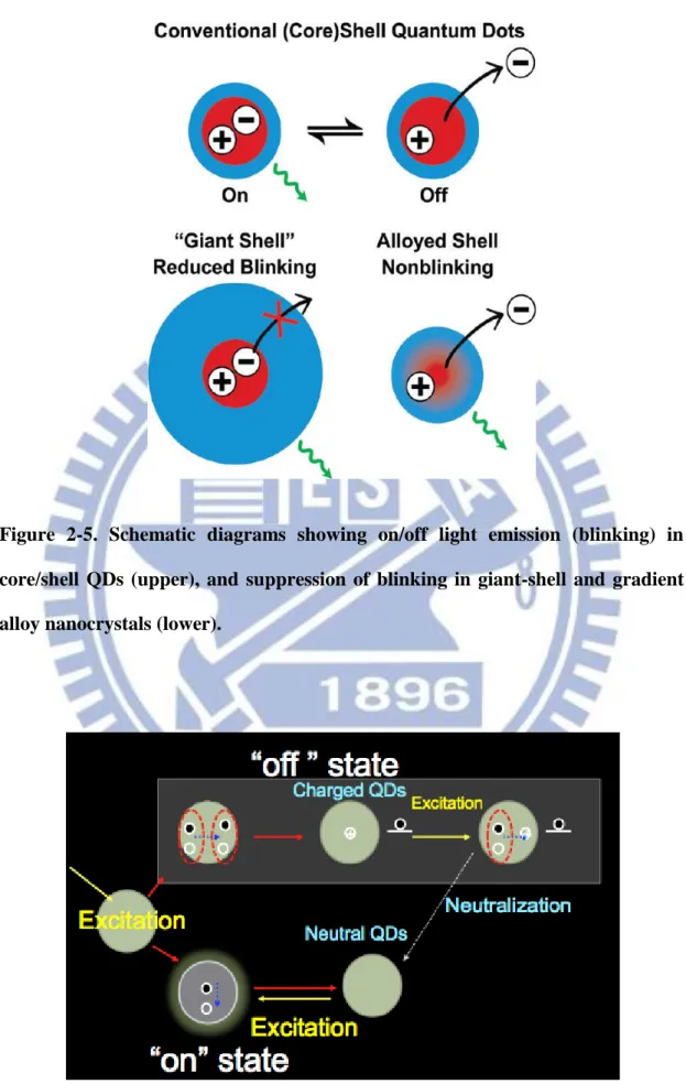
Figure 2-5. Schematic diagrams showing on/off light emission (blinking) in core/shell QDs (upper), and suppression of blinking in giant-shell and gradient alloy nanocrystals (lower).
Figure 2-6. Explain the blinking phenomena which is based on non-radiative Auger process.
22
2-4 Organic molecules
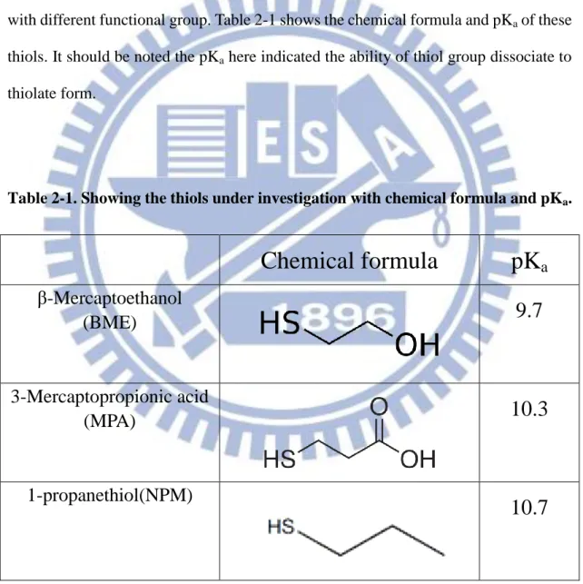
Organic molecules have been proved to play a significant role for the properties of the inorganic semiconductor QDs, and thiol-containing short chain molecules could suppress blinking behavior of single QDs. Here we choose some organic molecules accord with our experiments. That are β-Mercaptoethanol(BME), 3-Mercaptopropionic acid (MPA), and 1-propanethiol(NPM). Where BME has been studied for a long time, and it will be a good bridge to other research. MPA and NPM are similar to BME, only with different functional group. Table 2-1 shows the chemical formula and pKa of these
thiols. It should be noted the pKa here indicated the ability of thiol group dissociate to
thiolate form.
Table 2-1. Showing the thiols under investigation with chemical formula and pKa.
Chemical formula
pK
aβ-Mercaptoethanol
(BME)
9.7
3-Mercaptopropionic acid
(MPA)
10.3
1-propanethiol(NPM)
10.7
23
Chapter 3 Experiment methods and Apparatus
3-1 Transient absorption two color pump-probe measurement
In Semiconductor QDs, some physical mechanisms influence the photoinduced carrier dynamics. Several measurements have been used to investigate it. However, femtosecond laser pump-probe system has been shown to be the most powerful tool to read the temporal and spectral dynamics of the carriers. The laser pulse width can achieve femtoseconds, and it’s short enough to measure scattering or relaxation processes in QDs. The semiconductor QDs under investigation is excited by the pump pulse, the charge carriers will transit from valence band to conduction band, then relax back to valance band through various relaxation processes. Another weaker laser pulse, called probe pulse, will reach the sample with suitably delayed respect to the pump pulse by introducing an optical delay in its path. The probe pulse laser detected the transient photo-absorption (TA) signal in a continuous time domain.
Normally, the probe power is much weaker than the pump power, and the spot size on the sample is smaller than the pump to ensure measuring a uniform photoexcited density. The data is expressed in the form of the normalized differential transmission given by ΔT / T0
Eq. (3-1)
Where ΔT(t) = T(t) – T0 is the change in transmission induced by the pump, T and T0 are
the transmission of the probe in the presence and absence of the pump, respectively. The resulting signal is proportional to the sum of electron and hole distributions at the probe photon energy and therefore has the potential to separately measure electron and hole dynamics in semiconductor QDs. This contrasts with other ultrafast spectroscopic
24
techniques such as TRPL, in which the measured signal is proportional to the product of the electron and hole distributions, preventing separate measurements of electron and hole dynamics [2].
In order to obtain a flexible system, a non-degenerate (pump and probe at different wavelengths) measurement over a broad spectral range is required. Below we will show the experiment setup in detail.
25
3-1.1 Wavelength tunability and optical parametric amplifiers
Second harmonic generation (SHG) is a simple nonlinear laser technique to generate sum frequencies. Two laser pulse have interactions in nonlinear crystals such as BBO (β-barium borate), LBO (lithium triborate), KTP (KTiOPO4). Fulfilled the phase-matching condition, as equation shows below:
ω3 = ω1 + ω2 ( ω3 = ω1 - ω2)
κ3 = κ1 +κ2
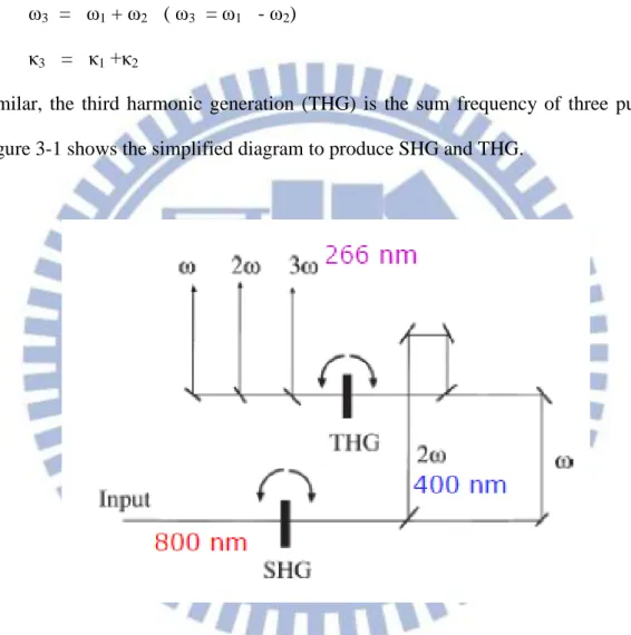
Similar, the third harmonic generation (THG) is the sum frequency of three pulses. Figure 3-1 shows the simplified diagram to produce SHG and THG.
Figure 3-1. The simplified diagram to produce SHG and THG. The first nonlinear crystal produce SHG signal (400nm), and interacted with fundamental pulse in the second nonlinear crystal, reproducing THG signal (266nm). Dichroic mirrors are added to extract the specified frequency.
26
In our system, a laser pulse pass (800nm) through focal lens focused on nonlinear b-barium borate (BBO) crystal with a large χ(2), generating a double frequency pulse (400nm). It’s take 40-50% conversion efficiency for 800 nm to 400 nm. Usually, we choose a sufficiently thin nonlinear crystal to reduce the group velocity dispersion (1mm). This 400nm pulse laser acted as the pump beam.
Optical parameter amplifiers (OPA), as illustrated in Figure 3-2, show the principle of the OPA for extending the wavelengths. Firstly, 800 nm ultrashort pulses can be easily obtained as the fundamental, and 400 nm and 266 nm pulses can be obtained by nonlinear second harmonic generation (SHG 400 nm) and third harmonic generation (THG 266 nm), respectively. A white-light continuum pulse with ultrashort width is generated as a seed by a focused pulse (800 nm) passing through a sapphire plate. Pumped by the fundamental, the OPA oscillates and emits both signal and idler beams with perpendicular polarizations and tunable near infrared wavelengths. Then the signal and idler can mix with the fundamental to generate visible wavelengths through sum frequency generation (SFG). The second harmonic of the signal or idler can also mix with the fundamental to generate visible and ultraviolet output. Thus, the OPA system, through nonlinear techniques, can produce ultrashort pulses with wavelengths extending from the near infrared to the ultraviolet.
This wide range pulse laser is used as the probe beam source for its flexible wavelength. We use a commercial OPA system pumped by the Ti:sapphire regenerative amplifier laser (TOPAS-C, Spectra Physics). It is a two stage parametric amplifier of white-light continuum. Briefly, there are some blocks including: pump beam delivery and splitting optics, white light continuum generator, a pre-amplifier or first amplification stage, a signal beam expander-collimator and a power amplifier or second amplification stage. We use a personal computer to control translation stage and rotation stages so that allow for a fast and precise optimization of positions of certain
27
optics when tuning the output wavelength of TOPAS-C. We use 550nm laser because of the B1 of QDs under investigation.
Figure 3-2. Principle of OPA for extending the wavelengths through nonlinear interaction.
28
3-1.2 Experimental system of pump probe setup
The transient absorption (TA) pump probe system setup is shown in Figure 3-3. It is based on a Ti:Sapphire amplified laser (Spitfire, Spectra Physics) with maximum output about 1mJ, 1kHz repetition rate, and central wavelength of 800nm. The output of the laser was split by a 90-10 beamspliter, with the higher power portion transmitted into OPA as probe beam and lower power portion being frequency doubled in a 1mm BBO crystal as pump beam. The pump beam was modulated at 100Hz by an optical chirp. To avoid coherent interference and isolate two pulses, the calcite polarizer and half-wave plate pair is added to two pulses ensuring the polarizations of pump and probe beam are perpendicular to each other. The pump and probe beams were made collinear and focused at the sample with convex lens. We monitored the absorption signal with a silicon photodiode module (New focus 2001), the output of which was fed into a lock-in amplifier (Stanford Research Systems, SR830).
The intensities of the pump and probe beams were controlled by a combination of neutral density filters, polarizers, and half-wave plates. The ratio of the pump probe power is about 60:1. The relative delay between the pump and beams was controlled with a stepper motor-driven translation stage. Pump beam size is about 110μm/diameter after SHG with confocal lenses. The time resolution of our instrument is estimated to be 0.2ps (Gaussian FWHM). This is broader than the transform-limited pulse width of the Ti:Sapphire oscillator, mainly due to dispersion through the focusing objective [36, 37].
29
(a)
(b)
Figure 3-3. (a) Two color transient absorption pump-probe measurement setup. (b) The real photo of pump-probe setup.
30
3-2 Temperature dependent PL measurement
A detailed study of the QDs photophysics with a particular attention to nonradiative processes is not only interesting for fundamental physics, but it is also relevant to the exploitation of nanocrystals in practical applications. To date, several relaxation processes have been proposed to explain the photophysics of CdSe QDs, including the thermally activated exciton transition from dark to bright states and carriers surface localization in trap states [38]. As the result, a key aspect for understanding the fluorescence behavior is through studies of the radiative and non-radiative processes, which govern the temporal decay and the quantum yield of the fluorescence. Such investigation can be obtained through examination of the temperature dependence of fluorescence. It has been shown that at room temperature the main nonradiative process in CdSe/ZnS core/shell QDs is thermal escape, assisted by multiple longitudinal optical (LO) phonons absorption, while at low temperature evidence for carrier trapping at surface defects was found [39]. Despite these results, the role and the chemical origin of the surface defect states in the radiative and nonradiative relaxation in nanocrystals has not been clarified completely [40, 41].
The temperature dependent experimental setup was shown as Figure 3-4. A 406 nm CW laser with a power of 50 mW was used as an excitation source, and was attenuated using a neutral density filter with an optical density of 1.5 in order to avoid extra irradiation effects during the measurements. The excitation beam was spatially limited by an iris and unfocused. The excitation density on the surface is estimated to be 50mW/cm2. Fluorescence was collected into a MicroHR spectrometer (HORIBA Jobin Yvon) with a 1200 per mm grating and recorded by a cooled CCD (SynapseTM CCD). The spectral resolution of the system is around 0.5 nm. The sample was installed in a cryostat (ST500) in vacuum with controllable temperature between 77 and 450 K when using liquid nitrogen. For each sample, we perform PL
31
measurements in the temperature range from 77K to 300K (room temperature) in steps of 20K.
32
(a)
(b)
Figure 3-4. (a) Simply show the temperature dependent fluorescence experimental setup. (b) The real photo of the system.
33
3-3 Sample preparing
The CdSe/Zns core/shell QDs with polymer layer surrounded was purchased from Invitrogen Canada Inc. The Absorption and fluorescence spectra of QDs show in Figure 3-4. The short chain thiols including β-Mercaptoethanol(BME), 3-Mercaptopropionic acid (MPA), and 1-propanethiol(NPM). All these thiols (20mM) were added to the QD (0.2μM) in aqueous phase so that the molar ratio of thiol/QD is 105. The pH value of QD solution is 8.3. For transient absorption measurement and steady-state fluorescence measurement, the samples were placed in 3 mm quartz cell with absorbance about 0.3-0.4. However, for temperature dependent fluorescence measurement, the film samples were fabricated by conventional drop casting onto the glass substrates evaporated under vacuum ensuring the aging time short enough. The long aging time (24 hours incubation) sample is the same case.
34 400 450 500 550 600 650 700 0.0 0.2 0.4 0.6 0.8 1.0
(a)
In
te
n
si
ty (
a
.u
.)
wavelength (nm)
Absorption_QD565nm 450 500 550 600 650 0.0 0.2 0.4 0.6 0.8 1.0(b)
In
te
n
si
ty (
a
.u
.)
wavelength (nm)
PL_QD565nmFigure 3-5. (a) The absorption and (b) the fluorescence spectra of CdSe/ZnS core/shell QDs used in this study. The B1 feature (first absorption peak) is around 550nm and the PL peak is around 565nm at room temperature.
35
Chapter 4 Results and discussion
4-1 Transient absorption
The transient absorption spectroscopy is a convenient tool for probing the charge recombination dynamics of semiconductor QDs. The absorption traces pumped at 400nm and probed at 565nm (first excitonic peak) are presented in Figure 4-1. Previous ultrafast studies of semiconductor QDs have shown that the transient absorption signals are strongest near the band edge [16]. The signal level in the measurements is ΔI/I ~ 10-4
-10-5 so that we can be readily detected. The bleaching recovery at the first excitonic peak has been employed to monitor the influence of surface modification as well as interfacial electron transfer processes. The time resolved absorption traces are fit by double exponential function: a fast one on the order of several tens of picoseconds, followed by a much longer one on the order of nanosecond. Mainly, the fast decay observed in the transient absorption signal was represented by variety of possible processes: electron-phonon coupling, charged carrier trapping or Auger recombination [42]. To confirm the photo-physics of this CdSe/ZnS core/shell QDs, we performed intensity dependent measurements [37]. If Auger recombination is a significant effect, we would expect that both the time constant and the relative amplitude of the fast decay depend on pump intensity [16, 42]. The higher pump power will correspond to shorter lifetime. Figure 4-1 shows transient absorption traces recorded at different pump intensities from QD in aqueous phase. The fast time constant does not depend on the pump intensity, for the range of power 0.03-0.24μJ/pulse (<N0> =0.5-4). These results are not consistent with Auger
recombination.
The above discussion implies that the fast decay for the CdSe/ZnS QDs arises from either trapping of charge carriers into defect states, presumable at the surface of
36
the QDs, or from electron-phonon coupling [2]. However, the electron-phonon coupling time constant for CdSe/ZnS QDs is usually in sub-ps. Thus, the electron-phonon coupling process should be complete within the time of the pump pulse in our experiments and cannot be responsible for this fast exponential decay. Therefore, the transient absorption trace in Figures 4-1 is assigned to charge carrier trapping at surface states in the CdSe/ZnS QDs. Figure 4-2 shows the enhancement in degree of surface passivation by thiols lead to slower dynamics of the single e-hole pair state, indicating that short-chain thiols affect the defect state at QD surface. Since the transient absorption trace take approximately 1hour to collect, we only perform the TA data of QD aged with thiols for 24hr. Double exponential function fitting result shown in table 4-1 for Figure 4-2. The average lifetime is calculated as
Eq. (4-1)
The average lifetime of original pure QDs is about 1.6 ns, lower than other thiol-containing QDs from 1.8 ns to 2.8 ns. It should be noted MPA show strongest surface passivation, where NPM only has little enhancement. In this experiment, we can only obtain electron dynamics (1Pe to 1Se) yet nothing with hole dynamics.
37
Figure 4-1. Transient absorption traces at the 1Pe to 1Se for the CdSe/ZnS QDs in
aqueous phase taken with different pump laser powers (shown in the figure).
-100 0 100 200 300 400 500 600 700 800 0.00000 0.00004 0.00008 0.00012 0.00016
time delay (ps)
240W 120W 60W 30W 6W38 -100 0 100 200 300 400 500 600 700 800 0.0 0.2 0.4 0.6 0.8 1.0
T/T
Delay time (ps)
CdSe/ZnS QDs BME MPA NPMFigure 4-2. Transient absorption spectra for CdSe/ZnS QDs with different short chain thiol-containing molecules at 24 hours aged.
Table 4-1. Show the double exponential function fitting parameters of Figure 4-2. The last row indicates the average decay lifetime.
H2O BME MPA
NPM
A
1 0.29169 0.26747 0.26603 0.31439τ
1(ps)
36.96271 36.57142 37.22371 33.17446A
2 0.64578 0.66737 0.63467 0.60236τ
2(ps)
2307.994 3380.936 3964.77 2790.90439
4-2 Steady-state fluorescence
The photoluminescence (PL) spectra were recorded by JASCO fluorescent FT-6300 at room temperature, operating at 400nm as the excitation source. Here we used 3 different molar ratio of thiol/QD ~ 105, 106, and 107. The ratio 105 could cause blinking suppression of single QDs, while QDs direct quench the PL at ratio ~107 observed in Jeong’s experiment [11]. Since BME have been studied for a long time, this thiol was used in our thiol / QD molar concentration ratio experiment. Figure 4-3 shows the steady-state fluorescence spectra of three BME/QD concentration ratios vs. aging time.
Obviously, comparing to pure QDs, other three lines show different trends. BME/QD concentration ratio ~105 enhances PL vs. time while BME/QD ratio ~106 enhances PL as soon as BME added, then quench PL slowly. However, the BME/QD ratio ~107 quench directly. These three trends suggest the interaction of thiols capping on QDs surface.
The BME/QD 105 ratio shows PL enhancement, which could related to surface passivation via electrons donation to a surface trap state. Here, the BME interact with QD only by weaker coordination-type bonds through the sulfur lone-pair electrons. It would prevent the core electrons eject to the defect sites on the surface. At this ratio, BME will maintain thiol form, and keep blinking suppression thus PL keep the enhancement. At BME/QD ratio ~106, BME shows higher PL enhancement compare to 105, but slowly quench which indicate a stronger covalent-type bonds was formed for long time incubation. Thiol form transfer to thiolate form and the new hole trap sites would be produced and PL decreased. At this BME/QD concentration ratio (106), we could clearly see the competition of two mechanisms.
At highest BME concentration, BME is 7 order higher than QDs, BME thiol form transfer to thiolate immediately, and PL steady decreased. That means the thiolate
40
and QDs bound soon and loses the ability to suppress blinking. From these results, we could confirm the critical concentration of thiol/thiolate or coordination-type bonds /covalent-type bonds conversion and successfully combined to aging time.
Following we checked the differences of three thiol-containing molecules with QDs. Figure 4-4 shows the steady-state fluorescence spectra of three thiols with QDs vs. aging time. The thiol / QD molar concentration ratio is 105. Compared to pure QDs (black line), thiols all enhance the PL intensities in the short time. However, after long incubation, these short chain thiols exhibit different performances. BME keeps PL enhancement as mentioned; MPA starts to quench merely 10 minute incubation; and NPM only with little variation (green line almost overlaps with black line). Figure 4-4 hints about these thiols have different experiment results in this study.
41 0.1 1 10 120 160 200 240 280 320 360
P
L i
nte
ns
ity (
a.u
.)
Time (hr.)
BME_6 order BME_7 order H2O BME_5 orderFigure 4-3. Steady-state fluorescence spectra of CdSe/ZnS QD with three different BME/QD molar concentration ratios vs. time.
42 5 10 15 20 25 30 200 250 300 350 400 450
PL (5 order)
PL inten
si
ty
(
a.u.)
Time (hr.)
H2O
BME
MPA
NPM
Figure 4-4. Steady-state fluorescence spectra of CdSe/ZnS QD with three short chain thiols (5 order concentration ratios) vs. time.
43
4-3 Time resolved photoluminescence
Transient absorption spectrum only used to study electrons dynamics. To monitor dynamics of photoexcited holes, the time-resolved photoluminescence (t-PL) measurement was used [11]. Here we used up-conversion technique to measure PL lifetime in several ns time scale. In the previous section, we studied three different BME/QD molar concentration ratiosPL spectrum to confirm the relation of aging time and concentration. Now, the same condition (BME concentration and incubation time) was applied to further gain insight into the mechanism of PL increase/subsequent decrease/decrease directly. The experiment result was shown in Figure 4-5.
Compared to pure QDs (black line), 5 order and 6 order concentration BME have an increase in PL amplitude immediately. After 24 hours incubation, 6 order BME quenched and decay faster than pure QDs while 5 order BME only has little decrease, but its lifetime still longer than pure QDs. Finally we measured 7 order concentration of BME and obtained the shortest PL lifetime as expected. The amplitude enhancement/subsequent quench/quench directly of different concentration are well consistent with steady-state PL spectrum. An initial PL increase can be explained as a reduction in the number of electron traps and subsequent PL decline as formation of hole traps. The direct observation of electron trap passivation and its correlation with enhanced PL is unique in terms of connecting a specific thiol-QD interaction with a positive impact on QD PL.
44
Figure 4-5. Time-resolved photoluminescence spectra of CdSe/ZnS QD with three different BME/QD molar concentrations ratios and measured immediately and 24 hr incubation. 0 500 1000 1500 2000 1
PL lifetime
0min_BME_5order 0min_BME_6order H2O 24hr_BME_7order 24hr_BME_6order 24hr_BME_5orderP
L
in
ten
sit
y
(a.
u.
)
Delay time (ps)
45
4-4 Temperature dependent fluorescence
4-4-1 Fluorescence intensity
In the QDs and these thiols aging time line, we measure the temperature dependent PL at short time (10min) and long time (24hr). The temperature dependent fluoresceence spectra of CdSe/ZnS and short chain thiol-capped QD film as a function of temperature from 77K to 300K, as shown in Figure 4-6. As the temperature increases, the PL spectra show a red-shift of the peak energy, increasing broadening and decreasing intensity. It is noteworthy that all the fluorescence properties are reversible in this temperature-dependent measurement.
These measurements, especially at low temperature, are important for revealing the influence of the thiol group on the PL properties, because PL measurements at low temperatures are sensitive to defects or localized states. Figure 4-6 (b), (c), and (d) shows the temperature dependence PL spectra of QDs with thiols. The defect-related PL band with a large Stokes shift of ~ 0.47 eV is dominant at low temperatures, while the relative intensity of the band-edge PL increases with increasing temperature. There is no obvious change at defect-related PL band as soon as these thiols added (10min). However, 24hr later, the QDs defect intensity decrease with BME and MPA.
46 500 550 600 650 700 750 800 0 4000 8000 12000 16000
(a)
H 2O P L (a .u .) wavelength (nm) 77K 100K 120K 140K 160K 180K 200K 220K 240K 260K 280K 300K 500 550 600 650 700 750 800 0 5000 10000 15000 20000 25000 30000 35000 (b) BME / 10 min P L (a .u .) wavelength (nm) 77K 100K 120K 140K 160K 180K 200K 220K 240K 260K 280K 300K 500 550 600 650 700 750 800 0 5000 10000 15000 20000 25000 30000 35000 (b) BME / 24hr P L (a .u .) wavelength (nm) 77K 100K 120K 140K 160K 180K 200K 220K 240K 260K 280K 300K 500 550 600 650 700 750 800 0 10000 20000 30000 40000 50000 (c) MPA / 10 min P L (a .u .) wavelength (nm) 77K 100K 120K 140K 160K 180K 200K 220K 240K 260K 280K 300K 500 550 600 650 700 750 800 0 5000 10000 15000 20000 (c) MPA / 24 hr P L (a .u .) wavelength (nm) 77K 100K 120K 140K 160K 180K 200K 220K 240K 260K 280K 300K47 500 550 600 650 700 750 800 0 5000 10000 15000 20000 25000 30000 35000 (d) NPM / 10 min P L (a .u .) wavelength (nm) 77K 100K 120K 140K 160K 180K 200K 220K 240K 260K 280K 300K 500 550 600 650 700 750 800 0 2000 4000 6000 8000 10000 (d) NPM / 24 hr P L (a .u .) wavelength (nm) 77K 100K 120K 140K 160K 180K 200K 220K 240K 260K 280K 300K
Figure 4-6. The first plot is the temperature dependent fluorescence of pure QDs. The lower 6 figures show the PL with short chain thiols: BME, MPA, and NPM at 10 min and 24 hours at left and right side, respectively.
48
Basically, some possible processes resulting in excited electron relaxations in the QDs including radiative relaxation, Auger nonradiative scattering, thermally activated trapping in surface and/ or defect/impurity states. In our experiments, the excitation density was very low and thus Auger scattering could be ruled out. Therefore, the nonradiative relaxation is most likely due to thermal activation of nonradiative trapping, which are often observed in semiconductor bulk, quantum dots and core/shell structure quantum dots [43].
At low temperatures, the non-radiative channel is not thermally activated so that the excited electrons can radiatively relax and emit photons. Once the temperature is increased, the nonradiative channels are thermally activated, such as trapping by surface/defect/ionized impurity states, as expressed below:
Eq. (4-2)
Where Ea is the activation energy and KB is Boltzmann’s constant. The quantum
efficiency can be expressed as:
Eq. (4-3)
Where R and NR are radiative and nonradiative lifetimes, respectively.From equation
4-2 and 4-3, the nonradiative lifetime decreases with and increasing temperature, which result in a decreasing in the quantum efficiency and fluorescence intensity.
To further study the fluorescence spectra, a single Gaussian function was used to fit the band-edge PL peak. Figure 4-7 is the Arrhenius plot of the QDs with thiols fluorescence intensity from Gaussian function fitting. These fluorescence intensity
49
(arbitrary unit) vs. reciprocal temperature points (1/K) were fit using equation shown below,
Eq. (4-4)
The activation energy suggests the probable barrier of excited electron relaxes through nonradiative process. The activation energies of QDs and with thiols were extracted shown in table 4-2.
Figure 4-7. Arrhenius plot of fluorescence intensity for the edge-band of QDs with thiols. Evidently, pure QDs (black line) and BME, MPA, and NPM with 10 min and 24 hours (color line) incubation have large variation.
0.002 0.004 0.006 0.008 0.010 0.012 0.014 0.0 0.2 0.4 0.6 0.8 1.0

![Figure 2-3. Showing the absorption and fluorescence spectra for electron-rich and cation-rich QDs situation [21]](https://thumb-ap.123doks.com/thumbv2/9libinfo/8621747.191583/30.892.133.756.119.908/figure-showing-absorption-fluorescence-spectra-electron-cation-situation.webp)