Contributed Paper
Manuscript received April 15, 2009 0098 3063/09/$20.00 © 2009 IEEE
Low Complexity Synchronization Design
of an OFDM Receiver for DVB-T/H
Ting-Chen Wei, Wei-Chang Liu, Chi-Yao Tseng and Shyh-Jye Jou
Abstract —In this paper, an OFDM baseband receiver for DVB-T/H is presented. The receiver contains four synchronizations, an OFDM symbol synchronization, a carrier synchronization, a sampling clock synchronization and a scattered pilots synchronization. This paper proposes several novel designs to reduce the synchronization latency and hardware complexity. The carrier and clock synchronization loops are fully digitalized schemes. The scattered pilots synchronization adopts a two stages scheme to reduce the detection latency. In addition, the pre-filling scheme reduces the latency of channel estimation. The design result shows that the equivalent gate count is about 810K gates including 102.8KB memory 1.
Index Terms —OFDM, Synchronization, DVB
I. INTRODUCTION
Digital video broadcasting terrestrial and handheld (DVB-T/H) [1], [2] are proposed by European Telecommunications Standards Institute (ETSI) to transmit digital TV signal. The DVB-T/H standard adopts orthogonal frequency division multiplexing (OFDM). In the DVB-T/H, there are three symbol lengths, 2048 (2K Mode), 4096(4K Mode) and 8192 (8K Mode) and four guard interval (GI) lengths which are used for with different channel. Besides, continual pilots, scattered pilots and transmission parameter signaling (TPS) pilots are inserted in the frequency domain. The continual pilots have fixed position, the scattered pilots change their position every OFDM symbols and the TPS is used to transmit system parameters. The data subcarriers can use several different constellation schemes like, quadrature phase-shift keying (QPSK), 16 quadrature amplitude modulation (QAM) and 64QAM.
In a DVB-T/H system, there are four required synchronization (sync.) for the receiver, such as the OFDM symbol sync., the carrier sync., the clock sync., and the scatter pilot sync. The OFDM symbol synchronization [3] usually uses the repeated signals of the cyclic prefix. The carrier frequency offset (CFO) and sampling clock offset (SCO) can be estimated in the frequency domain [4]-[6]. With the improvement of the digital signals processing, the
1This work is supported by National Science Council, CIC and MediaTek
of Taiwan, under grant number NSC 95-2220-E-009-008.
T. C. Wei, W. C. Liu and S. J. Jou are with the Department of Electronics Engineering, National Chiao Tung University, Hsinchu City, Taiwan 300.
C. Y. Tseng is with Department of Electrical Engineering, National Central University, Taoyuan County, Taiwan 300
compensation of SCO is translated into the digital domain [7], [8] to relax the specifications of the analog device. In the DVB-T/H system, the scatter pilot synchronization typically uses the TPS to detect the scatter pilot mode. To reduce the detection latency, two fast scatter pilot synchronizations are reported in [9], [10].
In our previous work, a jointed Mode/GI/symbol detection scheme has been proposed in [3]. In this work, several novel schemes are proposed to reduce the hardware complexity and synchronization latency. First, a phase predictive scheme is proposed to reduce the operations of the phase accumulator in the numerically controlled oscillator (NCO) and interpolator controller. Then, a differential encoding of pilots position is used to reduce the required memory storage. Second, a two stages scattered pilot synchronization scheme is proposed to reduce the detection latency and hardware complexity. Finally, a scattered pilots pre-filling scheme reduces the latency of channel estimation.
This paper is organized as follows: In Section II, the baseband receiver block diagram and the demodulation flow are introduced. Section III focuses on the carrier and clock synchronization. Section IV shows the two stages scatter pilot synchronization scheme and the scattered pilots pre-filling scheme. Performance and hardware implementation results are shown in Section V. Finally, Section VI is the conclusions of this paper.
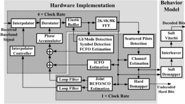
II. RECEIVER ARCHITECTURE AND DEMODULATION FLOW Fig.1 shows the block diagram of the DVB-T/H baseband receiver. In the receiver, the Mode/GI/Symbol detection [3], the carrier synchronization, the sampling clock synchronization and the channel estimation (inner receiver) are designed and implemented into gate level. The soft demapper, the interleaver, and the soft Viterbi decoder (outer receiver) are behavior models which are used to measure the receiver performance. The hardware implementation contains two clock rate domains. One is 4X clock rate and the other is 1X clock rate. The derotator, the interpolator and the 2K/4K/8K multimode FFT operate at 4X clock rate. On the other hand, the Mode/GI/Symbol detection, the channel estimation, the integer CFO (ICFO) estimation and the jointed SCO and residual CFO (RCFO) estimation [4]-[6] work at 1X clock rate.
The demodulation flow has two stages: the acquisition stage and the tracking stage. In the acquisition stage, the receiver detects the transmission Mode and the GI length, finds the OFDM symbol boundary, compensates the fractional
CFO (FCFO) and estimates ICFO. Then, the demodulation flow enters into the tracking stage. In the tracking stage, the receiver tracks SCO and RCFO. After getting into the steady state, the receiver detects the scattered pilot mode, does channel estimation [11], equalization and demaps the constellation into bits stream.
Fig. 1. The DVB-T/H receiver architecture III. CFO AND SCOSYNCHRONIZATION A. CFO and SCO Compensation
This work adopts a cubic Lagrange interpolator [7], [8], [12] to compensate SCO. The mathematic descriptions of the interpolation are shown in [7], [8]. The cubic Lagrange interpolator uses four samples to construct a required sample. When the required timing exceeds the valid range, the interpolator controller requires to change the sample set. This work sets the valid range within ±0.5 sample [13]. The valid range, [-0.5, 0.5) is efficient for hardware implementation. The comparator of the interpolator controller can only examine the first two bits instead of a whole word comparison to reduce the power consumption. The CFO compensation is composed of a derotator and a sinusoidal value generator. This work uses the coordinate rotational digital computer (CORDIC) [14] based derotator [15]. The conventional derotator needs a complex multiplier and the sinusoidal value generator requires hardware for implementation. A CORDIC-based derotator combines them to reduce hardware complexity.
B. Phase Prediction
The samples within the GI period can be dropped after finding the OFDM symbol boundary. Hence, the interpolator and the derotator can stop working for power saving. However, the phase accumulators (ACC) of the NCO and the interpolator controller must keep working within the GI period for phase continuity. Our previous work proposed a phase prediction scheme [16]. The frequency offsets are estimated once at each OFDM symbol, so the estimated frequency offset is a constant within an OFDM symbol. Then, the estimated frequency offset multiplied by the GI length is the total phase offset of GI. As a result, the total phase offset during GI is also a constant. With this scheme, the NCO and the interpolator controller can stop working within the GI period; then, it predicts and compensates the total phase of the GI
period at the beginning of the next OFDM symbol. Moreover, because the GI length of DVB-T/H is a power-of-two number, the multiplication of the phase prediction can be replaced with the shifting operation for area saving. Fig.2 is the simulation waveforms of the phase prediction scheme. It shows that this scheme can keep the phase continuity and reduces 3%-20% operations of phase accumulators for different GI lengths.
Fig. 2. Phase prediction of the phase accumulators C. Architecture of Jointed RCFO and SCO
This work adopts a three steps method for the carrier frequency synchronization [4]-[6]. The CFO is composed of FCFO and ICFO in an OFDM system. At the symbol boundary detection, the result of the delay correlation is also used for estimating FCFO. ICFO is estimated in frequency domain by using pilots. However, the FCFO estimation cannot calculate perfectly. A residual CFO (RCFO) still remains. Hence, a jointed RCFO and SCO estimation [4]-[6] in the frequency domain is used to keep tracking RCFO and SCO at every OFDM symbol before convergence.
The architecture of the jointed RCFO and SCO estimation is also shown in Fig.3. The ‘tan-1’ module calculates the angle of
a complex number and this module adopts the CORDIC algorithm. To smooth the RCFO and SCO estimation, the loop filters [17] are added into the synchronization loops. The coefficients of the loop filters are designed as power-of-twos; therefore, the multipliers can be replaced with wire-shifting.
Fig. 3. Architecture of jointed RCFO and SCO estimation D. Differential Encoding
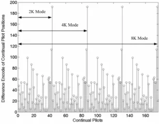
The jointed RCFO and SCO estimation [4]-[6] requires the continual pilot positions to distinguish pilot subcarriers from data subcarriers. Our previous work proposes a differential encoding method for recording the continual pilot positions [16]. The distribution of the differential encoding positions is periodic as shown in Fig.4; hence, the receiver only requires to record one period of the distribution. The storage cost of the original method is 2301 (177 × 13) bits; in contrast, the storage cost of
the differential encoding method is 360 (45 × 8) bits. However, the length of ROM must be a power-of-two. Hence, the implemented storage size becomes 512 (64 × 8) and is reduced by 77%. The design overhead is an accumulator and a control unit to accumulate the difference values.
Fig. 4. Difference encoding of continual pilot position E. Simulation Results
Fig.5 (a) shows the simulated register transfer level (RTL) output SNR for different FCFOs (in subcarrier spacing). Another simulation for different SCOs (in ppm) relative to 1X sample rate is shown in Fig.5 (b). The simulation results show the receiver can keep tracking under different frequency offsets. Besides, Fig.5 shows that the upper bound performance of the receiver is about 33 dB in output SNR.
Fig. 5. Output SNR of difference FCFOs and SCOs
IV. SCATTED PILOTS SYNCHRONIZATION A. Fast Scattered Pilots Synchronization
The position of scattered pilots is recorded in TPS pilots. To decrease the detection latency, two fast scattered pilot synchronization (SPS) algorithms are reported in [9], [10]. One is Power-Based (PB) algorithm shown in (1) [9], [10] and the other is Correlation-Based (CB) algorithm shown in (2) [9], [10]: ( ) ( ) ⎪⎭ ⎪ ⎬ ⎫ + × + × ⎪⎩ ⎪ ⎨ ⎧ + × + =
∑
= 4 mod * 0 mod4 3 4 12 , ( ) 3 4 12 , ( max arg max k p n SC k p n SC SP p p k PB (1) ( ) ( ) ⎪⎭ ⎪ ⎬ ⎫ + × + − × ⎪⎩ ⎪ ⎨ ⎧ + × + =∑
= 4 mod * 0 mod4 3 4 12 , 4 ( ) 3 4 12 , ( max arg max k p n SC k p n SC SP p p k CB (2)Where SC(n,m) is the mth sub-carrier of the nth symbol, k is the possible scatter pilots mode and SP is the estimated scatter pilots mode. Both algorithms use the boosted power [1], [2] of the transmitted scatter pilots. The summation of correlation of the scatter pilots is usually larger than that of the data subcarriers. Therefore, the PB and CB algorithm can distinguish the scattered pilots from the data subcarriers.
B. Hardware Complexity of SPS
The PB algorithm requires two real multipliers and one real adder to correlate with the conjugate of itself, one adder to do summation and four register groups to store the correlation results of the possible scattered pilot location. On the other hand, due to the complex number operations of the CB algorithm, it requires a complex multiplier (three real multipliers and five real adders [18]). Moreover, double register groups are required for recording the real part and the imagine part of the correlation result. Besides, an absolute value unit (two real multipliers and one adder) is required. Furthermore, an extra storage element is required to store the possible subcarriers of the pervious symbol. For example, the CB algorithm requires a 2272 words memory to store the scattered pilots. The hardware complexities of PB and CB algorithm are shown in Table I.
TABLEI
HARDWARE COMPLEXITY OF PB AND CBALGORITHM
Real multiplier Real adder Register group Memory Latency (symbols) PB 2 2 4 0 1 CB 5 8 8 words 2272 5
C. Proposed Two stages Fast Scattered Pilots Sync. Our previous work proposes a two stages SPS scheme [19] to improve the reliability. The two stages scheme is illustrated in Fig.6. This scheme operates SPS twice. The first SPS is used to detect the scattered pilot mode of the current symbol and the second one is used to ensure the prediction of the first one. If the detected scattered pilot mode from the second SPS is not the same as the predicted mode from the first one, the system will think that an error happened and redo the two stages SPS scheme. The first and second SPS can either the PB algorithm or the CB algorithm. Table II lists different combinations and their synchronization time. Because the CB algorithm requires pervious symbol, the detection latency is long. Therefore, if the CB algorithm is used in the two stages algorithms, the detection latency will also be long. Besides, when an error happened, the latency of the two stages PB-PB algorithm which redoes once still has smaller latency than the CB algorithm.
Fig. 6. State diagram of the two stages SPS TABLEII
SYNCHRONIZATION TIME OF COMBINATIONS ( UNIT : OFDM SYMBOL) PB CB PB-PB PB-PB PB- PB-CB CB-PB CB-CB No
Error 1 5 2 3 5 6 6
An
Error N/A N/A 4 6 10 12 12
D. Simulation Results
A performance comparison of the original SPS and the two stages SPS scheme is shown in Fig 7. In addition, a three-stage PB-PB-PB SPS scheme is carried out in the simulation. In the simulation result, the single stage CB has better performance than the single stage PB and the two stages PB-PB; however, the detection latency of the single stage CB is much longer (five OFDM symbols). Moreover, the performance of the three-stage PB-PB-PB is close to the single stage CB. By considering the detection latency, error penalty and hardware complexity, this work adopts the two stages PB-PB for the scatter pilot synchronization. The latency of the two stages PB-PB SPS algorithm is four OFDM symbols when an error happened. In hardware implementation, it requires two real multipliers, two real adders and four register groups; besides, it does not require memory storage to record the pervious data.
Fig. 7. Performance of the two stages and three stages SPS scheme
E. Scattered Pilots Pre-Filling Scheme
For the purpose to reduce the latency of the channel estimation, our previous work proposes a channel estimation (CE) storage pre-filling scheme [19]. Fig.8 illustrates this pre-filling scheme. The scattered pilots pre-filling scheme stores the four possible scattered pilots groups at the first SPS. When doing the second SPS, this scheme uses the prediction SP mode from the first SPS to store the subcarriers of the successive OFDM symbol. If the second SPS is the same as the prediction from the first SPS, the pre-filled subcarriers are supposed to be the scattered pilots. If they are not equal, the SPS will restart and the pre-filled subcarriers will be ignored. By using the pre-filling scheme, the latency of channel estimation can reduce one OFDM symbol time.
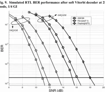
Fig. 8. Illustration of the scatter pilot pre-filling scheme V. SYSTEM PERFORMANCE AND DESIGN RESULTS A simulation environment is build to verify the performance and functionality of the receiver. The channel models use Ricean (F1) and Rayleigh (P1) channel provided in the DVB-T/H standard [1], [2]. As shown in Fig.1, the baseband receiver is designed with Verilog hardware description language in RTL and synthesized to gate level implementation. According to the DVB-T/H standard, the required bit error rate (BER) after Viterbi decoder is 2 × 10⁻⁴. Fig.9 and Fig.10 shows that the BER performance results which can achieve the required BER.
The synthesis result of the DVB-T/H receiver shows the equivalent gate counts is about 810K gates (including Memory). The total memory requirement of this receiver is 102.8KB (99KB SRAM and 3.8KB ROM). Among the memory requirement, 76KB SRAM and 3.7KB ROM are for the 2K/4K/8K FFT, 21KB SRAM is for the channel estimation and the Mode/GI/Symbol detection, and 2KB SRAM and 0.1KB ROM are for synchronizations. The summary of the design result is shown in Table III.
TABLEIII
SYNTHESIS RESULTS OF THE RECEIVER
Equivalent Gate Count Required Memory Bits FFT 500K (62%) 79.7KB Mode/GI/Symbol Detection & CE 223K (28%) 21KB CFO/SCO Estimation 57K (7%) 2.1KB CFO/SCO
Compensation & others 30K (3%) 0
Total 810K 102.8KB
Fig. 9. Simulated RTL BER performance after soft Viterbi decoder at 2K mode, 1/4 GI
Fig. 10. Simulated RTL BER performance after soft Viterbi decoder at 8K mode, 1/4 GI
VI. CONCLUSION
This paper shows the architecture of an OFDM baseband receiver for DVB-T/H. The receiver integrates a Mode/GI/Symbol detection, a multimode FFT, a channel estimation, a carrier frequency synchronization loop, a sampling clock synchronization
loop and a two stages scattered pilots synchronization. When there is no input noise, the output SNR of the receiver is about 33dB. A novel phase predictive scheme reduces 3%~20% operations of phase accumulators for different GI lengths. The differential encoding scheme reduces the required storage size by 77%. The proposed PB-PB two stages scatter pilots synchronization scheme has smaller latency and hardware complexity. Moreover, if extreme low error rate is required, the performance of the PB-PB-PB three stages scheme is close to that of the CB algorithm. Furthermore, the scattered pilots pre-filling scheme reduces the latency of the channel estimation by one OFDM symbol time. The synthesis results show that the equivalent gate count of the DVB-T/H receiver is about 810K gates including 102.8 KB memory.
REFERENCES
[1] ETSI, “Digital Video Broadcasting (DVB); Framing Structure, Channel Coding and Modulation for Digital Terrestrial Television, European Telecommunication Standard EN 300 744 V1.5, Nov. 2004.
[2] ETSI, “Digital Video Broadcasting (DVB); Transmission System for Handheld Terminals (DVB-H),” European Telecommunication Standard EN 302 304 V1.1.1 Nov. 2004.
[3] T. C. Wei, W. C Liu and S. J. Jou, "A jointed mode detection and symbol detection scheme for DVB-T," IEEE Trans. Consumer Electronics, vol. 54, no. 2, pp.336–341, May 2008
[4] M. Speth, S. A. Fechtel, G. Fock and H. Meyr, “Optimum receiver design for wireless broadband systems using OFDM—part I ,” IEEE Trans. Commun., vol. 47, no. 11, pp. 1668–1677, Nov. 1999.
[5] M. Speth, S. Fechtel, G. Fock and H. Meyr, “Optimum receiver design for OFDM-based broadband transmission part II: A case study,” IEEE Trans. Commun., vol. 49, no. 4, pp. 571–578, Apr. 2001.
[6] S. A. Fechtel, "OFDM carrier and sampling frequency synchronization and its performance on stationary and mobile channels," IEEE Trans. Consumer Electronics, vol. 46, no. 3, pp.438–441, Aug. 2000
[7] F. M. Gardner, “Interpolation in digital modems-part I: Fundamentals,” IEEE Trans. Commun., vol. 41, no. 3, pp. 501–507, Mar. 1993.
[8] L. Erup, F. M. Gardner and R.A. Harris, “Interpolation in digital modems-part II: Implementation and performance,” IEEE Trans. Commun., vol. 41, no. 6, pp. 998–1008, June 1993.
[9] L. Schwoerer, J. Vesma, "Fast scattered pilot synchronization for DVB-T and DVB-H," in Proc. 8th International OFDM Workshop, Hamburg, Germany, Sept. 2003.
[10] L. Schwoerer, “Fast pilot synchronization schemes for DVB-H,” in Proc. 4th International Multi-Conference Wireless and Optical Communications, Canada, July 2004, pp.420–424
[11] T. A. Lin, C. Y. Lee, “Predictive equalizer design for DVB-T system,” in Proc. ISCAS 2005, vol. 2, May 2005, pp. 940–943.
[12] C. W. Farrow, “A continuously variable digital delay element” in Proc. ISCAS 1988, June, 1988, pp. 2641–2645.
[13] T. P. Wang, T. D. Chiueh, "A low-complexity fractional delay all-pass filter design for time-domain interpolation," in Proc. IEEE VLSI-DAT 2007, April 2007, pp.1-4
[14] J. E. Volder, “The CORDIC trigonometric computing technique,” IRE Trans. Electron. Computers, vol. C-8, pp. 330–334, Sept. 1959.
[15] Y. Ahn, S. Nahm and W. Sung, “VLSI design of a CORDIC-based derotator,” in Proc. ISCAS 1998, May 1998, pp. 449–452.
[16] C. Y. Tseng, T.C. Wei, W.C. Liu and S. J. Jou, “Low power and power aware design for DVB-T/H baseband inner receiver,” in Proc. IEEE VLSI-DAT 2007, Apr. 2007, pp. 1–4.
[17] J. S. Wu, M. L. Liou, H. P. Ma and T. D. Chiueh, “A 2.6-V, 44-MHz all-digital QPSK direct-sequence spread-spectrum transceiver IC,” IEEE JSSC, vol. 32, no. 10, Oct 1997, pp.1499–1510
[18] A.Wenzler and E. Luder, “New structures for complex multipliers and their noise analysis,” in Proc. ISCAS 1995, vol. 2, May 1995, pp. 1432–1435. [19] W.C. Liu T.C. Wei, and S. J. Jou, “Two-stage scattered pilot
synchronization with channel estimation scattered pilots pre-filling for DVB-T/H, ” in Proc. IEEE VLSI-DAT 2007, Apr. 2007, pp. 1–4.
Ting-Chen Wei received the BS in electrical engineering from the National Central University at Taiwan in 2003 and the MS in electrical engineering from National Central University in 2005. He is currently a PhD candidate in the department of electronics engineering at National Chiao Tung University.
Wei-Chang Liu received the BS in electrical engineering from the National Central University at Taiwan in 2004 and the MS in electronics engineering from National Chiao Tung University in 2006. He is currently a PhD student in the department of electronics engineering at National Chiao Tung University.
Chi-Yao Tseng was born in Taiwan in 1982. He received his B.S. degree from the Department of Electrical Engineering, Tatung University in 2004 and M.S. degree from the Department of Electrical Engineering, National Central University in 2006. He joined ELAN Microelectronics Corp., Hsinchu, Taiwan, in 2006.
Shyh-Jye Jou received his B. S. degree in Electrical Engineering from National Chen Kung University in 1982, and M. S. and Ph.D. degrees in Electronics from National Chiao Tung University in 1984 and 1988, respectively.
He joined Electrical Engineering Department of National Central University, Chung-Li, Taiwan, from 1990 to 2004 and became a Professor in 1997. Since 2004, he has been Professor of Electronics Engineering Department of National Chiao Tung University and became the Chairman from 2006. He was a visiting research Associate Professor in the Coordinated Science Laboratory at University of Illinois, Urbana-Champaign during 1993-1994 academic years. In the summer of 2001, he was a visiting research consultant in the Communication Circuits and Systems Research Laboratory of Agere Systems, USA. He served on the technical program committees in CICC, A-SSCC, ICCD, ISCAS, ASP-DAC, VLSI-DAT and other international conferences. His research interests include design and analysis of high speed, low power mixed-signal integrated circuits, and communication integrated circuits and systems.