Red Fluorenes as the Efficient Host Emitter for Non-Doped Red
Organic Light-Emitting Diodes
Chih-Long Chiang,
a.bMin-Fei Wu,
bChing-Fong Shu,*
aand Chin-Ti Chen*
b aDepartment of the Applied Chemistry, National Chiao Tung University, Hsinchu, Taiwan
30035
b
Institute of Chemistry, Academia Sinica, Taipei, Taiwan 11529
ABSTRACT
Crystallinic red fluorophores based on donor-acceptor substituted spirofluorene, i.e., PhSPDCV show strong fluorescence in solution (Φf ~ 70 %) as well as in solid state (Φf > 30 %). Non-doped red OLEDs
fabricated with PhSPDCV exhibit authentic red (CIE, x = 0.65, y = 0.35) electroluminescence with brightness over 12,000 cd m-2 (or > 600 cd m-2 at 20 mA cm-2) and remarkable external quantum efficiency as high as 3.6%. On the other hand, the bis-substituted derivatives of spirofluorene BisPhSPDCV show relatively weak fluorescence both in solution (Φf < 20 %) and in solid state (Φf < 10 %). Although saturated red
electroluminescence (CIE, x = 0.65, y = 0.34) is also observed, non-doped red OLED containing
BisPhSPDCV performs much worse than PhSPDCV OLEDs. Both PhSPDCV and BisPhSPDCV are not
amorphous forming loosely packed crystallinic materials in solid state with no intimate π-π interaction.
Keywords: Red, non-doped, organic light-emitting diode, fluorene, spiro.
1. INTRODUCTION
Doping the emissive materials in a host matrix has been a practical method in improving the performances of organic light-emitting diodes (OLEDs) since the convincing demonstration by Tang et al of Kodak.1 Particularly, this powerful method has be most beneficial for the red emissive OLEDs because of the concentration-quenching nature of most red emissive materials in solid state.2 However, problems associate with the doping method have emerged recently. For red OLED with a reasonable performance, the doping level of the red dopant has to be limited to a small number of weight percent, and the number as low as a fraction of one weight percent is not uncommon.1,2 Furthermore, ideal doping level is usually within a narrow concentration range of the dopant. A bathochromic fluorescence shift up to 75 nm dependent on dopant concentration has been reported on the pyran-type dopant.3,4
*
With sensitive emission variation and the need of strict control on doping level, doping is unlikely to be a favored approach in the mass production of OLED, which requires high consistency on product quality. We and others have recently showed that several judiciously designed red fluorophores can be applied in the fabrication of bright and efficient red OLEDs as non-doped host- emitting materials.5-10 From the experimental evidences, it has been stressed that the non-crystallinity or amorphous glass state is one of the critical factors that make red-emitting materials applicable to non-doped red OLEDs.
Br a2 b c Br Br a1 b c Br Br Br N N N Ph Ph Ph Ph Ph O O O Ph O O O N N N Ph Ph Ph Ph Ph Ph CN NC CN NC NC CN Br PhSPDCV BisPhSPDCV
Scheme 1. Reagents and conditions: a1) n-BuLi, THF, -78 oC, then DMF, RT, 3 h, 7; a2) TiCl4, dichloromethyl methyl ether, CH2Cl2, RT, 12 h; b) diphenylamine, Cs2CO3, Pd(OAc)2, P(t-Bu)3, toluene, 120 oC, 8 h; c) malononitrile, basic Al2O3, toluene, 70 oC, 16 h.
Here in this paper, we report two unusual red fluorophores based on donor-acceptor substituted spirofluorenes, namely PhSPDCV (Scheme 1). The new red fluorophores are crystallinic instead of amorphous but they show strong red fluorescence in solid state. Moreover, the performance of non-doped red OLEDs fabricated with these spirofluorenes could be very good with the brightness and efficiency surpassing any previous known non-doped red OLEDs. In sharp contrast, non-doped Red OLED fabricated with BisPhSPDCV, a bis-substituted version of PhSPDCV, show much inferior performance to PhSPDCV OLEDs.
2. RESULTS AND DISCUSSION
Devices were fabricated by sequential thermal vacuum deposition of different material. The substrate was an indium-tin-oxide (ITO) coated glass with a sheet resistance of <50 Ω/sq. The thickness of each deposited layer was determined by quartz thickness monitor. The cathode of Mg0.9Ag0.1 alloy was deposited
(50 nm) by coevaporation and followed by a thick layer of silver capping layer. Details of EL characterization of each device have been described before.11
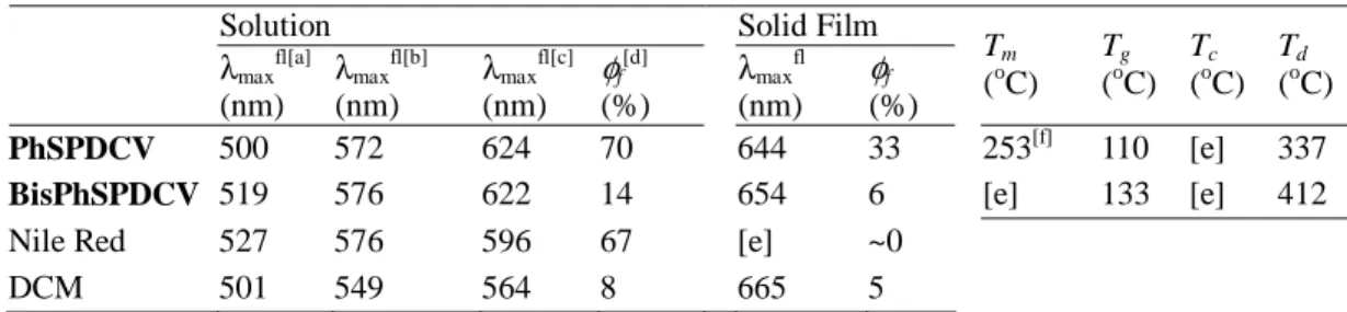
Table 1. Optical and thermal properties of red emitting PhSPDCV, BisPHSPDCV, Nile red, and DCM
Solution Solid Film
λmaxfl[a] (nm) λmaxfl[b] (nm) λmaxfl[c] (nm) φf[d] (%) λmaxfl (nm) φf (%) Tm (oC) Tg (oC) Tc (oC) Td (oC) PhSPDCV 500 572 624 70 644 33 253[f] 110 [e] 337
BisPhSPDCV 519 576 622 14 654 6 [e] 133 [e] 412
Nile Red 527 576 596 67 [e] ~0
DCM 501 549 564 8 665 5
[a] In hexanes. [b] In 1,4-dioxane. [c] In chloroform. [d] in 1,4-dioxane. [e] Not observed. [f] Only observed for the sample in the first heating scan.
Both PhSPDCV and BisPhSPDCV emit green (in hexanes), or yellow-orange (in 1,4-dioxane) to red (in chloroform or acetonitrile) fluorescence in solution highly depending on the solvent polarity (Table 1). This solvatochromic behavior is consistent with the charge-transfer characteristic of the donor-acceptor substituted red emitting fluorenes, and it is similar to that of Nile Red and DCM. However, in solid state, both spirofluorene derivatives show red fluorescence with λmaxfl > 640 nm (see Table 1), satisfying the
requirement for red OLEDs. In solution (1,4-dioxane), PhSPDCV exhibits intense fluorescence (solution fluorescence quantum yield φf is 70%), comparable with classical red fluorophore Nile Red (φf is 67%) but
much stronger than red laser dye DCM (φf is 8%) (Table 1). Conversely, they are all much brighter red
fluorophores compared with the dull Nile Red or DCM in solid state. The measurement of semi-crystallinic solid films indicated the solid film fluorescence quantum yields of red emitting spirofluorene PhSPDCV is 33% (Table 1), which are far higher than ~0% and 5% of Nile Red and DCM, respectively. This should be attributed to the anti-aggregation molecular design of the red emitting fluorenes. Therefore, unlike the red dopant of Nile Red or DCM, PhSPDCV are perfectly suitable as the red host emitters in the fabrication of non-doped red OLEDs. BisSPDCV can be considered as the dimmer version of PhSPDCV. However, it is very different from PhSPDCV in terms of fluorescence quantum yields. Surprisingly low solution fluorescence quantum yield of 14% was determined for BisSPDCV. We surmise that it is probably due to the dipolar coupling interaction that leads to emission quenching between two fluorophore moieties. If this is the case, it will be very intriguing to ask that how could it be possible that the dipolar coupling between two fluorophores moieties that are orthogonally aligned? This is worth of further experimental investigation.
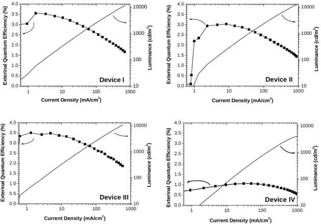
Device I shows the high electroluminance (L) of 11400 cd m-2 and external quantum efficiency (ηEXT)
of 3.6%, which is quite consistent with the high fluorescence quantum yield of PhSPDCV in solid state (Table 1). The performances of the red OLEDs can be further enhanced by the adjustment of the layer
thickness, such as the narrowing of the hole-transporting layer (NPB) and hole-blocking layer (BCP) as those in devices II.. The maximum luminance can be boosted over 12000 cd m-2 in device II with the same red chromaticity but in sacrifice of some efficiency. The lost efficiency can be mostly recovered by the widening the host-emitting layer (PhSPDCV) as well as the hole-blocking layer (BCP) shown in device III. It is noteworthy that the devices I-III all show reasonable stable efficiency (ηEXT) with only modest decay in
the low current density (I) range of 1-20 mA cm-2 (Figure 2), which is a satisfactory performance matching the need for active-matrix-driven devices. Particularly, device III exhibited relatively stable ηEXT (decrease
from 3.5 to 3.3%) in the current density up to 15-20 mA cm-2.
Table 2. Characteristics of OLEDs containing PhSPDCV or BisPhSPDCV.
Devices[a] Max. Luminance (cd m-2) Luminance, Efficiency, Voltage (cd m-2, %, V)[b] Max. Efficiency (%, cd A-1, lm W-1) λmaxel (nm) CIE 1931 Chromaticity (x, y) PhSPDCV I 11380 615, 3.2, 8.1 3.6, 3.5, 1.8 638 0.65, 0.35 PhSPDCV II 12410 557, 2.9, 7.3 3.0, 2.9, 1.4 636 0.65, 0.35 PhSPDCV III 10640 622, 3.2, 7.9 3.5, 3.4, 1.6 636 0.65, 0.35 BisPhSPDCV IV 2160 154, 1.0, 8.7 1.1, 0.8, 0.4 650 0.65, 0.34
[a] Device I: ITO/NPB(10 nm)/ PhSPDCV (40nm)/BCP (20 nm)/Alq3(30 nm)/Mg:Ag; Device II: ITO/NPB(5 nm)/
PhSPDCV (40 nm)/BCP (10 nm)/Alq3(30 nm)/Mg:Ag; Device III: ITO/NPB(10 nm)/ PhSPDCV (50nm)/BCP
(15nm)/Alq3(30 nm)/Mg:Ag; Device IV: ITO/NPB(10 nm)/ BisPhSPDCV (40 nm)/BCP (10nm)/Alq3(30 nm)/Mg:Ag.
[b] At current density of 20 mA cm-2 0.0 0.1 0.2 0.3 0.4 0.5 0.6 0.7 0.8 0.0 0.1 0.2 0.3 0.4 0.5 0.6 0.7 0.8 0.9 CIE 10 nm spacing CRT Device I Device II Device III Device IV 480 nm 520 nm 560 nm 600 nm Y X 300 400 500 600 700 800 900 0.0 0.2 0.4 0.6 0.8 1.0 Device I Device II Device III Device IV E L In te n s it y ( A .U .) Wavelength (nm)
Figure 1 CIE 1931 chromaticity diagram (left) and EL spectra (right) of device I-IV containing PhSPDCV and BisSPDCV, respectively.
1 10 100 1000 0.0 0.5 1.0 1.5 2.0 2.5 3.0 3.5 4.0 Device I 10 100 1000 10000
Current Density (mA/cm2)
E x te ri n a l Q u an tu m Ef fi ci en cy ( % ) Lum in a n c e ( c d/ m 2 ) 1 10 100 1000 0.0 0.5 1.0 1.5 2.0 2.5 3.0 3.5 4.0
Current Density (mA/cm2)
E x te ri n a l Q u a n tu m E ffi c ie n c y (% ) 10 100 1000 10000 Device II Lu m ina nc e ( c d /m 2 ) 1 10 100 1000 0.0 0.5 1.0 1.5 2.0 2.5 3.0 3.5 4.0
Current Density (mA/cm2)
E x te ri n a l Q u a n tu m E ffi c ie n c y (% ) 10 100 1000 10000 Device III Lu m ina n c e ( c d/ m 2) 1 10 100 1000 0.0 0.5 1.0 1.5 2.0 2.5 3.0 3.5 4.0 Device IV
Current Density (mA/cm2)
E x te ri n a l Q u a n tum E ffi c ie n c y (% ) 10 100 1000 10000 Lum in a n c e ( c d/ m 2)
Figure 2 EL intensity-external quantum efficiency-current density (L-ηEXT-I) characteristics of devices I-IV
This is the first demonstration that the stable efficiency can be achieved for host-emitting, non-doped, red OLEDs, which usually show sharp decay of EL efficiency even at medium range of current density or driving voltage.[6,7] It seems that the stability of device EL efficiency can be adjusted by the thickness of hole-transporting NPB or hole-blocking BCP in conjunction with the red light-emitting layers. It has been reported recently that the thickness of the NPB and BCP layers is critical for the red EL stability.10 Nevertheless, to our best knowledge, these devices exhibit some of the very best performances observed for fluorophore-based red OLEDs, either dopant or non-doped devices.12
Device IV shows relatively poor performance in all aspects. The device reaches maximum brightness of 2160 cd/m2 and peak external quantum efficiency of 1.1 %. Either one is significantly worse than that of Device I-III. We are quite surprised at the first glance of the results. However, this can be mainly attributed to the low fluorescence quantum yield of BisSPDCV in either solution or solid state (Table 1).
The crystal molecular structuresof PhSPDCV and BisSPDCV (Figure 3) reveal the unique non-planar molecular structure. Molecule wise, both fluorene parts of the spirofluorene moieties are essentially planar
as expected. While the dicyanovinyl acceptor is only slightly twisted (dihedral angle ~30o and ~15o for
PhSPDCV and BisSPDCV, respectively) from the coplanar conformation with the fluorene ring, the two
phenyl rings are twisted in large angle (~ 60o for both PhSPDCV and BisSPDCV) to the planar fluorene ring causing a distinct bulge, in addition to the rigid and bulky spiro-annulation PhSPDCV. Both structural features of arylamino bulge and orthogonal spiro-annulation are essential in preventing PhSPDCV molecule from close packing and hence severe fluorescence quenching.
Figure 3. X-ray determined molecular structure of PhSPDCV(left) and BisSPDCV (right).
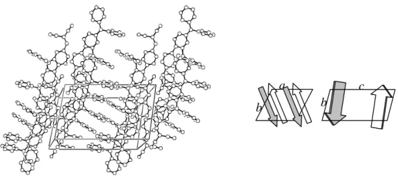
Figure 4. X-ray determined crystal packing diagram (left) of PhSPDCV with the removal of all hydrogen atoms for
clarity. The b-axis and c-axis are the vertical and the longest one, respectively. The sketch diagram on the right depicts the crystal packing of PhSPDCV. The arrows indicate the direction from arylamino to dicyanovinyl substituent.
b
c
b
b c
N C
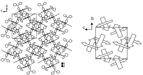
Figure 5. X-ray determined crystal packing diagram of BisPhSPDCV viewing from a-axis. All of the hydrogen atoms
are removed for clarity. The sketch diagram is shown on the right with the arrows indicating the direction from the arylamino to dicyanovinyl substituents.
Crystal packing wise, the crystal of PhSPDCV is composed of antiparallel arrays of each molecule approximately along b-axis of the unit cell (Figure 4). Each head-to-tail aligned repeating fluorene molecule in the crystal of PhSPDCV has an about 4~5 Å (about the half distance of a-axis) vertical displacement along the normal of the fluorene ring, which can be attributed to the intrusion of bulgy phenyl moieties in crystal packing. Such 4~5 Å separation makes vertical plane-to-plane π-π interaction between fluorene rings out of the reach in both crystals. In addition to several weak van der Waals non-π interactions, the weak dipole-dipole interactions in long distance appear to be the major force in holding the crystal packing together and causing the fluorescence quenching. On the other hand, the molecules of
BisPhSPDCV are packed in rather different fashion from that of PhSPDCV (Figure 5). Viewing from the a-axis of the crystal, the packing structure can be considered as the composition of pair wise BisPhSPDCV.
Whereas one half of each molecules is aligned head (diphenylamino group) to tail (dicyanovinyl group) forming a zigzag array along b-axis, the other half of each orthogonal spirofluorene moiety is distantly (> 6 Å) parallel to one and the other of adjacent molecules forming dimmer-like segregate structures. The crystal is loosely packed allowing room for accommodation of solvent molecules toluene (not shown in Figure 5) severely disordered in the crystal packing structure. Excluding the contact with solvent molecules, the closest van der Waals contact (3.75 Å) is between C24 of the fluorine moiety and C41 of diphenylamino
c b
moiety of adjacent molecules of BisPhSPDCV. This is not a π -π interaction, since the two π-systems are not parallel to each other. Furthermore, the π-systems are both laterally and axially displaced in a view perpendicular to the plane of the central ring. Accordingly, like the crystal packing of PhSPDCV, there is no close contact, particularly π -π interaction, found for the crystal of BisPhSPDCV. Therefore, we can conclude that the weak electroluminescence and hence low efficiency of BisPhSPDCV-based OLED is mainly due to the low fluorescence quantum yield of the molecules.
ACKNOWLEDGMENT This research was supported by National Science Council of Taiwan.
REFERENCES
1. C. W. Tang, S. A. VanSlyke, C. H. Chen, J. Appl. Phys. 1989, 65, 3610. 2. C.-T. Chen, Chem. Mater. 2004, 16, in press.
3. J. Kido, K. Hongawa, K. Okuyama, K. Nagai, Appl. Phys. Lett. 1994, 64, 815.
4. V. Bulovic, A. Shoustikov, M. A. Baldo, E. Bose, V. G. Kozlov, M. E. Thompson, S. R. Forrest, Chem.
Phys. Lett. 1998, 287, 455.
5. K. R. J. Thomas, J. T. Lin, Y. -T. Tao, C. -H. Chuen, Adv. Mater. 2002, 14, 822. 6. W. -C. Wu, H. -C. Yeh, L. -H. Chan, C. -T. Chen, Adv. Mater. 2002, 14, 1072. 7. H. -C. Yeh, S. -J. Yeh, C. -T. Chen, Chem. Commun. 2003, 2632.
8. T. -H. Huang, J. T. Lin, Y. -T. Tao, C. -H. Chuen, Chem. Mater. 2003, 15, 4584.
9. K. R. J.Thomas, J. T. Lin, M. Velusamy, Y. -T. Tao, C. -H. Chuen, Adv. Funct. Mater. 2004, 14, 83. 10. H. -C. Yeh, L. -H. Chan, C. -T. Chen, J. Mater. Chem. 2004, 14, 1293.
11. L. -H. Chan, R. -H. Lee, C. -F. Hsieh, H. -C. Yeh, C. -T. Chen, J. Am. Chem. Soc. 2002, 124, 6469. 12. T. -H. Liu, C. -Y.; C. H. Chen, Appl. Phys. Lett. 2003, 83, 5241.