Playback Dispatch and Fault Recovery
for a Clustered Video System with Multiple Servers
ING-JYE SHYU ejshue@dscs2.csie.nctu.edu.tw
SHIUH-PYNG SHIEH ssp@csie.nctu.edu.tw
Department of Computer Science and Information Engineering, National Chiao Tung University, Hsinchu, 30010, Taiwan, R.O.C.
Abstract. Recent technology advances have made multimedia on-demand services feasible. One of the chal-lenges is to provide fault-tolerant capability at system level for a practical video-on-demand system. The main concern on providing fault recovery is to minimize the consumption of system resources on the surviving servers in the event of server failure. In order to reduce the overhead on recovery, we present three schemes for recovering faulty playbacks through channel merging and sharing techniques on the surviving servers. Furthermore, to evenly distribute the recovery load among the surviving servers, we propose a balanced dispatch policy that ensures load balancing in both the normal server conditions and the presence of a server failure.
Keywords: fault tolerance, fault recovery, distributed multimedia systems, video-on-demand systems
1. Introduction
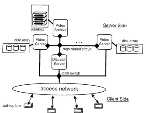
Video-on-demand (VOD) applications have recently received much attention from the telecommunications, entertainment and computer industries [3–5]. However, to provide VOD service demands high computing power and network bandwidth. Thus in this paper we propose an architecture which clusters a set of video servers for providing VOD services, as shown in figure 1. The VOD system consists of a dispatch server, a video archive and multiple cooperative video servers, which are connected by a high-speed circuit. The client requests/receives video data through the set-top-box. Each video server equips with a disk array which caches the most recent videos requested by the clients. The video archive is the repository of all videos. Viewer requests are first transmitted to the dispatch server via access networks and then dispatched to appropriate video servers for obtaining playback services. The video server retrieves the desired video either from its disk array or from the archive server.
The design of clustering a set of video servers is to provide fault-tolerant capability. For commercial VOD applications, fault tolerance is one of the most important issues. The common approach to providing fault tolerance uses redundancy, that is, organizing the redundant components as either active replication or primary backup units [1, 2, 7, 9, 10, 13]. In the primary backup scheme, the backup server is idle in the normal state and becomes active when the primary server fails. The drawback of this scheme is low utilization of the backup server. As for the active replication scheme, all servers work in parallel. When one of the servers fails, the workload on the failed server are transferred to the surviving servers. However, the workload transferred will overload some of the surviving servers if the
Figure 1. The architecture of a clustered n-server video system.
workload are not evenly distributed. Thus, to provide an effective fault-tolerant methodology under the consideration of minimizing the recovery overhead is the key focus of this paper. To cope with these problems, we propose three recovery schemes which reduces the recovery overhead while recovering the failed playbacks in the surviving video server.
To maintain workload and recovery load balancing among the video servers is the next key issue. T.D.C. Little and D. Venkatesh describe a probabilistic placement method that distributes videos to multiple disks [11]. Y. Wang et al. present some heuristic algorithms to place video files over the storage systems [15]. The IVSDNA prototype primarily de-scribes network design methodologies for a scalable, fault-tolerant interactive video system [16]. All these papers use different methodology to distribute the workload to different system components. In this paper, we focus on design of the dispatch policy to control the distribution of video playbacks to meet both the balance and reliability requirements.
We will also discuss how to dispatch the viewers’ playback requests such that the workload and recovery load are evenly distributed among the servers under normal condition as well as stress conditions (server failure or disk-array failure). In Section 2, we will present three recovery schemes, which are classified by the consumption of system resources, and a selection algorithm which instructs the surviving server to perform recovery by allocating the fewer system resources. Section 3 will present a dispatch policy to achieve even workload among the video servers under normal conditions, and even recovery load distribution in the presence of server failure. In Section 4, simulations are conducted to demonstrate the
effectiveness of the proposed schemes and policies. Section 5 concludes this paper and gives the future work.
2. Playback recovery
In this section three distributed playback-recovery schemes are presented, which are de-signed for the playback systems with clustered video servers. Accordingly, we propose a recovery selection algorithm for determining the best recovery scheme which exhausts the fewer resources in the surviving servers.
2.1. Notation and definitions
For clarity, we give some notations and definitions. A channel is defined as a set of system resources for providing a video playback, including a network stream to transfer video data to viewers, a disk I/O stream to read video data from the storage to system buffers, and intermediate buffers for caching video data between the network stream and the disk I/O stream. We assume that a video object is composed of a series of frames, and an I/O stream reads the frames from the storage to the buffers before delivering them to the viewers. Let
PMdenote the total number of frames in a video object. The current frame position read by an I/O stream of a channel C is denoted by Pc(C), of which the value ranges from 0 to PM. The network equipment allows the various viewers to share a channel for watching the same video. This capability is called multicasting [2, 6, 16]. Based on the multicasting mechanism, we can dynamically alter the progress speed of playbacks to enable different channels being merged or shared to improve resource utilization [8]. The playback speeds of a channel are classified as SMIN, SMAXand SNORMAL. Videos are usually played at SNORMAL speed, which is about 30 frames per second. SMAXis 5% faster than SNORMALand SMINis 5% slower than SNORMAL(There is an ample evidence indicating that effective display rates within±5% of SNORMALare not perceivable by viewers [8]). Let gap time G(C1, C2) be the distance in terms of frames between two I/O streams C1and C2. The channel in the failed server is specially called failed channel, denoted by CF.
2.2. Recovery schemes
Due to hardware limitation, the number of the channels a video server can support is limited. Therefore, a recovery scheme should consume as few channels during recovery as possible. Once all channels have been consumed for recovery, the server will not be able to provide additional playbacks for viewers during the recovery period. Thus we propose three recovery schemes which have different system resource requirements for recovery. In the system normal condition, the clustered video servers exchange and monitor the active/failure events through the internal high-speed channel. When detecting the failure of one of the video servers, the following recovery schemes are adopted by the surviving servers to recover the failed playbacks.
2.2.1. Recovery by allocation (RBA) scheme. This scheme is the most general method.
It allocates new channels, called the recovery channels, on the surviving servers and uses these channels to replace the failed channels in the failed video server. The recovery channel re-reads the same video object from the frame which the failed channel was reading, and then delivers it to the original viewers. Thus all viewers originally served by the failed channel can continue watching their video from the interrupted frame onward. This scheme achieves a fast response to server failures but requires new channel resource to perform playback recovery.
2.2.2. Recovery by merging (RBM) scheme. This scheme progressively merges channels
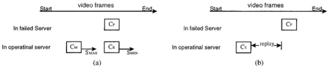
that are serving the same video object. As in the RBA scheme, a recovery channel CR is allocated to recover from the failed playbacks. Moreover, if a channel CM, located on the same server as CR, plays the same object as CF but was activated after CF, CM and CR can be progressively merged by altering their playback speeds from CR to SMINand CMto
SMAX, as shown in figure 2(a). After merging, the playback rate is readjusted to SNORMAL, and a channel can be released because the viewers served by CRand CMnow share a single channel through multicasting. The purpose of the merging process is to reduce the holding time of the allocated channel CR. The merging position of these two channels in terms of frames, denoted by Pm(CR, CM), is derived by Eq. (1), which states that the I/O streams of
CR and CM will meet at frame Pm. The feasibility of the merging process is evaluated in Eq. (2) under the constraint that the merging process must be completed before the playback is over.
(Pm(CR, CM) − Pc(CR))/SMIN= (Pm(CR, CM) − Pc(CM))/SMAX. (1)
Pm(CR, CM) ≤ PM (2)
The difference between RBM and RBA is the reduced holding time for the recovery channel. To minimize the channel holding time, it is important to select the right server to allocate the recovery channel. The selection criteria is that the server chosen must have a channel
CM which was activated after CF and has a minimal gap time with CR, (i.e., G(CR, CM) is minimal). In the next section, we present a dispatch policy which enables the server to select a failed playback to perform recovery.
2.2.3. Recovery by sharing (RBS) scheme. This scheme directly uses an existing channel
to provide playback for the failed channel. If the viewers can accept a period of repetition prior to continuation of the interrupted video, the playback may be directly recovered by a channel CS currently running after frame position Pc(CF), which satisfies the condition
G(CF, CS) ≤ TR, where TR is the maximal replay length that viewers can tolerate, as shown in figure 2(b). The advantage of this scheme is that it does not require resources on the recovery server because the recovery uses an existing playback channel to perform recovery. However, in the scheme, viewers incur replays of(Pc(CF) − Pc(CS))/SNORMAL seconds. The selection of CSalso has a significant effect on the replay length. Therefore, a surviving server with a channel CSthat has a minimal G(CF, CS) is preferred.
2.3. Recovery scheme selection
The RBS scheme uses fewer resources while performing recovery, but it requires the ex-istence of a channel playing the same object within the TR. The RBM scheme allocates a temporary channel to provide playback, but releases it after playback is merged with another existing channel. Compared with RBS and RBM, RBA is more interactive because the re-covery does not require an existing playback. However, RBA consumes a channel until the playback is complete and thus incurs the most overhead on the server. Considering the min-imization of the recovery overhead, the RBS scheme is the best preferable while selecting, followed by the RBM scheme, and then the RBA scheme. A Recovery-Scheme-Selection algorithm is presented in short below which is based on these selection principles. Algorithm. Recovery-Scheme-Selection Algorithm
Input: CF= the failed playback.
TR= the replay length that viewers can tolerate.
Begin
if∃ CSsuch that Pc(CS) ≤ Pc(CF) and G(CS, CF) is the smallest onethen
{
ifG(CS, CF) ≤ TRthen RBS is applied.
else ifa free channel is availablethen {
ifRBM is feasible (i.e., Eqs. (1) and (2) hold)then
RBM is applied. else RBA is applied. } else {
unable to perform recovery.
} }
else ifa free channel is availablethen { RBA is applied. } else {
unable to perform recovery.
} End
When the server has not enough resources to provide recovery, the server signals the viewers a failure on server and asks the viewers to re-subscribe the video again.
As the event of a server failure is detected, the surviving servers run this algorithm to select an appropriate scheme for each failed channel. However, in a distributed environment a decision problem arises: determining the server with the channel nearest the failed one is difficult. This problem may be solved by dispatching playback requests in a pre-determined sequences. This enables us to determine where the nearest channel locates. In the next section, we propose a dispatch policy that pre-determine the dispatch sequence of each video to the video servers and thus the policy achieves workload and recovery load balancing. 3. Balancing workload and recovery load
Viewer requests for obtaining playbacks are dispatched by the dispatch server to video servers. The dispatch server plays an important role to control the workload balancing among the video servers. In this section, we propose a special dispatch sequence for the dispatch server, thus workload balancing are achieved under the normal state and the failure of a server.
3.1. Playback request dispatch
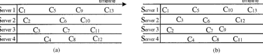
A server’s load can be characterized by the number of the active channels it has at any given time. The number of active channels is determined by the number of playback re-quests dispatched to that server. Thus, the dispatch policy used by the dispatch server will determine the degree of workload balance among video servers. The common dispatch policy balances load with a round-robin dispatch policy. For an n-server video system, the round-robin dispatch policy sequentially dispatches incoming requests to video servers to order playbacks. If the video server to which a request has been dispatched runs out of free channels, the request is queued in the dispatch server until a channel on that video server becomes available, even though other video servers may have free channels. Thus, the numbers of channels in use by all video servers will be the same. If in the meantime another request arrives also asking for the same object as the pending request, these two requests will be serviced together by dispatching both to a common channel later (through multicasting). The example in figure 3(a) shows requests being dispatched to four servers in this round-robin manner. These servers in turn allocate channels to provide playbacks.
Figure 3. (a) The round-robin dispatch policy; (b) The balanced dispatch policy.
This figure shows the time each channel is created. Consequently, the playback workload is evenly distributed among all servers.
Unfortunately, the round-robin dispatch policy leads to unbalanced load distributions when the recovery schemes are used to recover from a server failure. According to the recovery schemes, the channels nearest the failed channels are chosen to perform playback recovery in order to reduce the holding time or replay length. With the round-robin dis-patch policy, the nearest channels are all located on the same server. As the example in figure 3(a) shows, if server 2 fails, the channels in server 3 are the nearest ones to the failed channels. That is, if server 3’s channels are used to recover from the server 2’s interrupted playbacks, the recovery overhead, including the holding time of the temporary channels (for the RBM scheme) and the amounts of video replays to viewers (for the RBS scheme), will be minimized. However, it also leads to unbalanced distribution of the recovery load. Therefore, although the round-robin dispatch policy can balance workload distribution, it unfairly distributes recovery load to some dedicated server (if server i fails, all the recovery load fall on server i+ 1).
3.2. The proposed balanced dispatch policy
In order to avoid unbalanced recovery-load distributions, we propose a policy, called the
balanced dispatch policy, which uses a specially designed sequence to control the dispatch
of a viewer’s request to one of the video servers. The special sequence are called the
Balanced n-Cyclic code (BnC code). The BnC code is a cyclic sequence of the format
{G1, G2, . . . , Gn−1}, where each segment Gi is composed of n distinct numbers from 1 to n, and a cycle has n× (n − 1) numbers in total. This code guarantees an important property: for any two continuous numbers in any two segments, i.e., Gk = (. . . eiei+1. . .) and Gl = (. . . ejej+1. . .), if ei = ej, then ei+16= ej+1, where 1≤ l, k ≤ n − 1 and l 6= k. We have given a formal definition of the BnC code and proved that finding a BnC code for a given n is an NP-complete problem [14]. In Appendix A.1 we present an efficient heuristic algorithm to generate BnC codes for a large n.
An example of the B4C code is{1, 3, 2, 4, 1, 2, 3, 4, 3, 1, 4, 2}, which is used as a sequence to control playback dispatch, where G1 = 1, 3, 2, 4, G2 = 1, 2, 3, 4 and G3 = 3, 1, 4, 2. That is, requests are dispatched to servers according to the server order: 1, 3, 2, 4, 1, 2, 3, 4, 3, 1, 4, 2, and loops to the beginning, as shown in figure 3(b). Thus, according to this dispatch sequence, channels are evenly allocated among servers. Furthermore, in the event of a failure, no matter which server fails, the recovery load can be also fairly distributed to
the surviving servers by BnC inherent property. For example, assuming server 2 fails, the playbacks on C3, C6and C12are recovered by C4, C7and C13(the nearest channels) which are located respectively at servers 4, 3 and 1 when the RBM or RBS scheme is applied. If these two schemes cannot be applied due to condition mismatches, the RBA scheme is performed instead also by servers 4, 3 and 1. In this way, the balanced dispatch policy can effectively balance workload and recovery load among video servers in both normal conditions and fault recovery.
3.3. The recovery load balancing for multiple videos
Single-video balancing involves channels playing the same video object on various video servers. When a server fails, the surviving servers can easily determine which failed channels it should recover for through the information of the pre-determined dispatch sequence, and these servers adopt a lower cost recovery scheme according to the Recovery-Scheme-Selection algorithm described in Section 2.3.
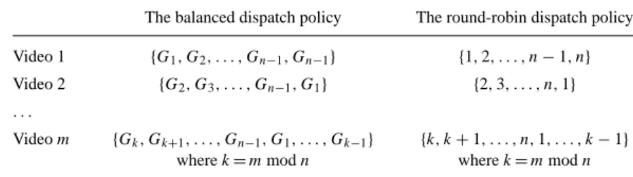
To support playing multiple videos simultaneously is also dealt with the same manner. We assign the same BnC code to each video as its dispatch sequence. According to the characteristics of the BnC code, channels for playing the same video object will be in balancing states with the point of long-term view. However, because of the usage of the same BnC code, a short-term unbalance of the system workload will occur at the beginning of the system startup. In order to eliminate the initial unbalanced situation, we present a shifted dispatch sequence as follows to balance both workload and recovery load for the case of supporting multiple video objects. Assume that a video system with m videos supported, these m video objects are sorted according to their popularity (as determined by request arrival rates) [12] in the first. Each video is assigned the same BnC code as its dispatch sequence, but each sequence has a different starting position. The starting position of the object k’s dispatch sequence is shifted right by n numbers from the starting position of object k− 1. Similarly, for the round-robin dispatch policy, the starting position of the object k’s dispatch sequence is shifted right by one number from the starting position of object k−1. Table 1 lists the shifted dispatch sequences for both policies. For the dispatch sequence without the shift is called the non-shifted dispatch sequence as compared with the shifted dispatch sequence. In the simulation of Section 4, we compare the effects of the shift and non-shift dispatch sequences.
Table 1. The shifted dispatch sequences for m video objects.
The balanced dispatch policy The round-robin dispatch policy Video 1 {G1, G2, . . . , Gn−1, Gn−1} {1, 2, . . . , n − 1, n}
Video 2 {G2, G3, . . . , Gn−1, G1} {2, 3, . . . , n, 1} . . .
Video m {Gk, Gk+1, . . . , Gn−1, G1, . . . , Gk−1} {k, k + 1, . . . , n, 1, . . . , k − 1}
4. Performance evaluation
Two sets of simulations are conducted in this section. The first one concerns with the effects of various recovery schemes. The second one simulates the variation of the balance degree of the workload and recovery load among video servers over the course of a week.
4.1. Simulation model and parameters
In our simulation, the number of video objects, m, is set to twenty. The movie length is fixed at 1.5 h. In the normal condition, the video playback speed SNORMALis 30 frames per second (fps). While applying merging operation, SMINand SMAXare adjusted to 28 and 32 fps respectively. The arrival distribution of viewer requests coming to the dispatch server is a Poisson process characterized by the mean inter-arrival time (MIAT). The probability of an arrival request for a specific object is determined by the object’s access frequency. The access frequencies of all the video objects in our simulation are characterized by a
Zipf ’s distribution with the parameter 0.1386 (In a Zipf distribution, if the objects are sorted
according to the access frequency, then the access frequency for the i th object is given by fi = c/i(i−θ), whereθ is the parameter for the distribution and c is the normalization constant [10, 17]. The assignment of 0.1386 toθ implies that 80% of the viewers ask for 20% of the objects, and the remaining 20% of the requests are for 80% of the objects. This phenomena is called the 80-20 rule. This rule makes the design of a video system more realistic by exploring the different popularity between popular videos and unpopular videos).
Requests for objects are thus dispatched to the proper video servers by the dispatch server according to each object’s dispatch sequence, and the access frequency determines which video object the dispatched request asks for. In our simulation, if we do not apparently indicate the number of video servers involved in the simulation, the video system was assumed to be consisted of six video servers. Each object was assigned a shifted B6C code as its dispatch sequence for the balanced dispatch policy (the B6C code is listed in Appendix A.2). As for the round-robin dispatch policy, each object’s dispatch sequence was determined according to the sequence listed at the right side of Table 1.
4.2. Comparison of various recovery schemes
In the first set of simulations, the dispatch server uses the balanced dispatch policy to dispatch each request. When a server failed, each video server invokes the Recovery- Scheme-Selection algorithm to pick suitable recovery schemes for the failed playbacks. MIAT herein is set to 60 s and TR5 min. The period of a server failure sampled in this simulation is set to an hour during the course of a week. That is, at every hour, assume a server fails and the percentage of the recovery schemes used by the surviving servers is counted. This value of the percentage is denoted as recoverability. The mean recoverability is calculated by averaging all the recoverability sampled for every hour during the course of a week. This value reflects the feasibility of each proposed recovery scheme. Table 2 shows the respective mean recoverability for different combination of the server number (N ) from
Table 2. The effects of the recovery schemes.a
For N= 4 and D values of: For N= 5 and D values of: For N= 6 and D values of:
1 2 3 4 1 2 3 4 5 1 2 3 4 5 6
RBS 35.0 32.6 35.3 35.0 33.7 34.8 33.8 36.2 34.4 34.9 33.2 35.7 34.3 35.4 33.7 RBM 20.0 20.6 19.9 20.8 20.3 21.0 21.2 18.9 20.3 20.2 21.0 19.9 21.2 19.8 20.3 RBA 45.0 46.8 44.7 44.1 46.0 44.1 45.1 44.9 45.3 44.9 45.7 44.4 44.4 44.8 46.0
For N= 7 and D values of: For N= 8 and D values of:
1 2 3 4 5 6 7 1 2 3 4 5 6 7 8
RBS 34.7 34.7 35.4 36.6 34.4 34.3 32.8 35.4 33.7 35.2 35.4 34.1 34.3 33.9 35.2 RBM 21.4 19.9 20.5 19.0 20.4 21.3 20.2 20.2 21.0 18.6 21.0 22.0 20.3 21.0 19.1 RBA 43.9 45.4 44.1 44.4 45.2 44.5 47.0 44.3 45.3 46.2 43.6 43.9 45.4 45.1 45.6
aValue given indicate percentage recovery.
4 to 8 under assuming a failed server (D). For example, consider the case of N = 4 and
D = 1. With the balanced dispatch policy, when server 1 in a four-server system fails,
the simulation shows that 35% of the failed channels will gain playbacks immediately by the RBS scheme; 20% of the failed channels also gain recovery immediately by the RBM scheme, which use much more system resource than RBS; only the remaining 45% of the failed channels are recovered by the RBA scheme. Through the simulation, it is observed that no matter how many servers are involved, in average, the RBS and RBM schemes save almost 55% of the free channels compared with those while using the RBA scheme alone.
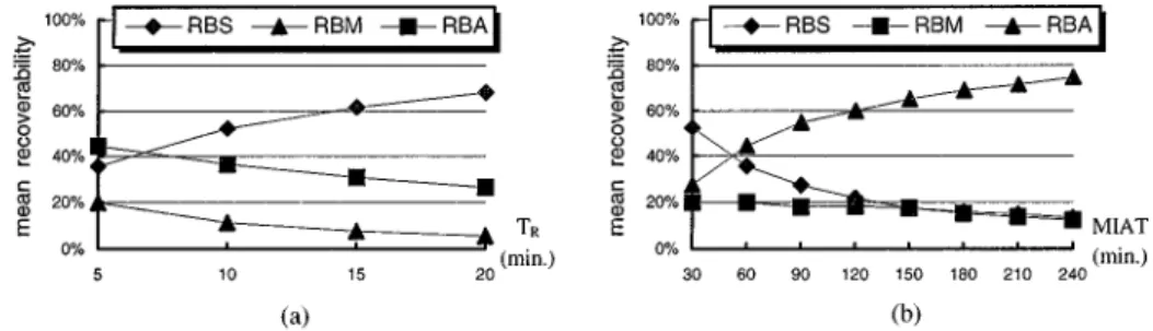
The next simulation explored the relationship between the mean inter-arrival time (MIAT) as well as TR (replay length the viewer can tolerate) and the mean recoverability of each recovery scheme. The mean recoverability represents how many percentage of the total failed channels can be recovered by a recovery scheme described in previous paragraph. By fixing the mean inter-arrival time at a 60 s interval, figure 4(a) shows the mean recoverability
of the three recovery schemes as TR increases. Note that the mean recoverability of RBS increases as TRincreases. This means that if viewers can tolerate longer video replays, more failed playbacks (35 vs. 75% of failed channels for 5 vs. 20 min replay duration) can be recovered by the RBS scheme, saving more free channels while performing recovery. The remaining playbacks are recovered with RBM and RBA respectively.
Figure 4(b) shows the mean recoverability as the number of requests coming to the system is reduced. Here TRwas held at 5 min. This figure shows the mean recoverability of the RBS and RBM schemes decreases as MIAT increases, but that of the RBA scheme increases. This means that an increase of mean inter-arrival time lengthens the time gap between channels playing the same object. Thus RBS or RBA is inappropriate for use and the probability of using RBA increases. Thus, if the requests arrived at the system concentrate on a period of a day, this behavior would result in a shorter MIAT and makes more RBS recovery. The “skew” property has been proved to be the practical behavior of the video-on-demand system [2, 10]. The peak of the coming requests locates on a period between 7:00 and 10:00 PM after a hard working day, for example.
4.3. Effects of dispatch policies
The second set of simulations monitored the balance degree of the workload and recovery load among video servers. A criterion BWL(t) is defined as the standard variation of the number of the active channels among the videos servers at time t. Larger BWL indicates more unbalanced workload distribution among servers.
BWL(t) = sPN i=1(Wi(t) − ¯W(t))2 N , where ¯W(t) = PN i=1Wi(t) N , 1 ≤ i ≤ N.
Wi(t) denotes the number of active channels in server i at time t. ¯W(t) is the mean of
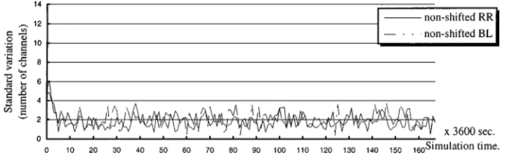
Wi(t) for 1 ≤ i ≤ N at time t. Figures 5 and 6 show the BWL for workload transitions over the course of a week for N = 6. Each point on the line represents BWL at time t for a specific policy. The reason why we plotted all simulation traces during a week is to illustrate the variation of BWL. These figures show that the balanced dispatch policy (BL)
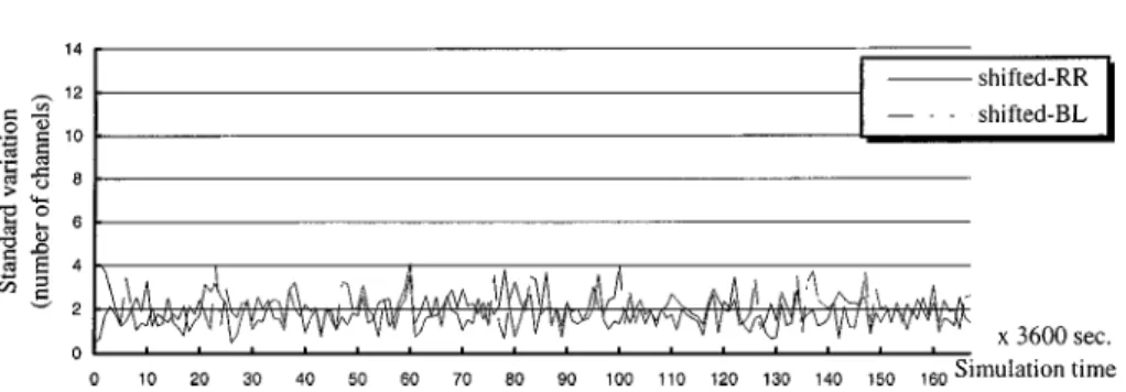
Figure 6. The transitions of the BWLfor the shifted dispatch sequence.
and the round-robin dispatch policy (RR) using the shifted and non-shifted sequences have similar effects and make BWLhave the same value around 2. This simulation demonstrates that both dispatch policies almost have the same power to balance the workload among the video servers. The improvement is that at the beginning of the lines in these figures we can observed that the shifted dispatch sequence makes BWLmore stable around the value 2 than the non-shifted ones which has a peak value 6 at the beginning. These results stressed that the workload of a multiple-server video system can be balanced by using the shift dispatch sequence.
The balancing states of the recovery load is the next case to be simulated. A criterion
BRLj is used to evaluate the balance degree of the recovery load distribution when assuming the server j fails.
BRLj (t) = sPN i=1 ¡ Rij(t) − ¯Rj(t)¢2 N , where ¯R j(t) = PN i=1R j i(t) N , 1 ≤ i ≤ N, i 6= j. Rij(t) denotes the number of channels which server i has to recover for after server j fails at
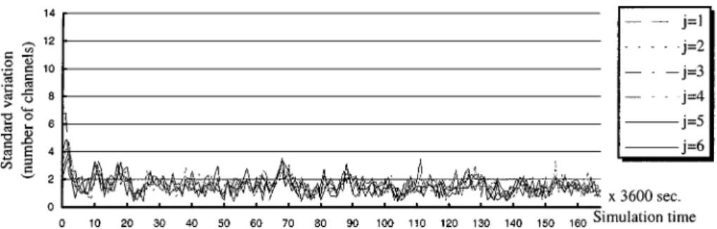
time t, no matter which recovery scheme is applied. Thus, the summation of Rij is the total number of channels in server j that need recovery, where i 6= j. BRLj represents the standard variation of Rij, where 1 ≤ i ≤ N and i 6= j. Figures 7–10 show the BRLj transitions in recovery-load distributions for shifted and non-shifted dispatch sequences using the
Figure 8. The transitions of the BRLj for the non-shifted balanced dispatch policy.
Figure 9. The transitions of the BRLj for the shifted round-robin dispatch policy.
Figure 10. The transitions of the BRLj for the shifted balanced dispatch policy.
round-robin and balanced dispatch policies, respectively. The reason why we plotted all the diagrams with the same y scale is to make a clear comparison between the results of different simulations. Each point on line j represents a BRLj when server j fails at that time instant. Figures show that the value of BRLj of the balanced dispatch policy is obviously smaller than that of the round-robin dispatch policy in general. This means that the balanced dispatch policy distributes recovery load more evenly among surviving servers than the round-robin dispatch policy does. Furthermore, figures 10 and 8 show that the value of BRLj by using the shifted dispatch sequence has the lower value than that by the non-shifted sequence for
the balanced dispatch policy. This means that the shifted balanced dispatch policy assures the balanced recovery-load distribution even during the server startup periods. According to the two sets of simulations above, we can conclude that the shifted balanced dispatch policy balances workload and recovery load, but the round-robin dispatch policy only balances workload.
5. Conclusion
In this paper, three playback recovery schemes are proposed to recover from video server failures in a clustered multiple-server video system. The RBA scheme always allocates a new channel while performing recovery. However, the RBM and RBS schemes significantly reduce the recovery overhead imposed on surviving servers. We have also presented two dispatch policies, the round-robin dispatch policy and the balanced dispatch policy, to control the workload and recovery load distributed to the video servers. The simulation results show that the proposed balanced dispatch policy effectively balances workload among the video servers not only under normal system conditions, but also in recovery process after server failures.
The balanced dispatch policy can evenly distribute the workload and recovery load among the servers. However, the configuration after tolerating a server failure can no longer provide balanced recovery load distribution when a second server failure occurs. In the near future, we hope to design a special dispatch policy which makes the recovery load distribution near balanced while recovering the second or more server failures.
Appendix A
A.1. An efficient heuristic method for finding a BnC code
Since we have proved that finding a BnC code is an NP-complete problem [14], in this appendix we give an O((n − 1)!) time complexity heuristic algorithm, the Find-BnC-code algorithm, which can efficiently generate a BnC code from a B(n − 1)C code. The idea be-hind of this algorithm is to insert the number n into some special positions in the B(n − 1)C code to form a BnC code.
Algorithm. Find-BnC Code Input: a B(n− 1)C code. Output: a BnC code. Begin
Step 1. Represent the input B(n− 1)C code as a series of connected arcs, (e1, e2), (e2, e3), . . . , (e(n−1)×(n−2), e1), in which eiis the i th number in the B(n−1)C code.
Step 2. Partition the arcs in Step 1 into n−1 groups in which each group Riconsists of arcs from(e(n−1)×(i−1)+1, e(n−1)×(i−1)+2) to (e(n−1)×i, e(n−1)×i+1), where 1 ≤ i ≤
n− 2.
Step 3. Select one arcs(vi, wi) from every Ri such that all vi are distinct, where 1≤ i ≤ n − 2.
Step 4. Step 3 produces total (n− 1)! combinations. For each combination, two arcs
(n, wx) and (vx, n) are generated, where 1 ≤ vx, wx≤ n − 1, vx6= wx,vx /∈ {vi | 1≤ i ≤ n − 2} and wx /∈ {wi | 1 ≤ i ≤ n − 2}. Then check these n arcs to see whether they form a Hamilton cycle. If yes, go to Step 5. Otherwise, go to Step 3 and try the next combination. When all the combinations have been tested and no Hamilton cycle is found, it means that the algorithm cannot find a BnC code from the input B(n− 1)C code.
Step 5. Extend the B(n− 1)C code into a BnC code by
a. inserting number n at the place located at between vi and wi in the B(n− 1)C code, where (vi, wi) is the arcs selected in Step 3 and 1 ≤
i≤ n − 2.
b. concatenating the formed Hamilton cycle (Step 4) to the tail of the B(n− 1)
C code to form a BnC code. End
Here we use the terminology from graph theory. The arc(v, w) is a directed edge from the vertexv to the vertex w. A Hamilton cycle is a path that passes through every vertex exactly once and returns to the start vertex.
An example is given to illustrate the algorithm Find a BnC code. Assume that we have a B5C code,{1, 2, 3, 4, 5, 2, 4, 1, 3, 5, 3, 1, 4, 2, 5, 4, 3, 2, 1, 5}. Partition it into four arc groups,
R51: (1, 2), (2, 3), (3, 4), (4, 5), (5, 2), R25: (2, 4), (4, 1), (1, 3), (3, 5), (5, 3), R53: (3, 1), (1, 4), (4, 2), (2, 5), (5, 4), R54: (4, 3), (3, 2), (2, 1), (1, 5), (5, 1). By exploring the computations in Step 3 and Step 4, we find that arcs (3, 4), (1, 3), (4, 2) and (5, 1) (respectively selected from groups R5 1, R 5 2, R 5 3and R 5
4) as well as two other generated arcs (6, 5) and (2, 6) can form a Hamilton cycle{1, 3, 4, 2, 6, 5}. We then insert number 6 into the B5C code at the positions between 3 and 4, 1 and 3, 4 and 2, and 5 and 1, then concatenate the formed Hamilton cycle {1, 3, 4, 2, 6, 5} to the tail of the B5C code. The B6C code thus obtained is {1, 2, 3, 6, 4, 5, 2, 4, 1, 6, 3, 5, 3, 1, 4, 6, 2, 5, 4, 3, 2, 1, 5, 6, 1, 3, 4, 2, 6, 5}.
Step 5a extends the B(n− 1)C code by removing arc (vi, wi) and inserting arcs (vi, n) and (n, wi). Because the inserted arcs (vi, n) and (n, wi) are disjoint for all 1 ≤ i ≤
n− 2, and the removed arcs (vi, wi) are also disjoint from the inserted B(n − 1)C code, so that the code formed by Step 5b is a BnC code. In Step 4, the worst case of finding a successful combination needs (n−1)! iterations, so the complexity for finding a BnC code is
O((n − 1)!). However, the heuristic algorithm may fail to find a BnC code from some
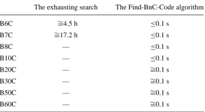
B(n − 1)C code. In this case, we can generate another B(n − 1)C code as a seed to repeat the same procedure, and then the BnC code may be found. We have developed a program that uses the above B5C code as a seed to find other BnC codes. Our experiments showed that our heuristic approach can find a BnC code much faster than the exhausting search. Table 3 shows the time needed for searching a BnC code by comparing the exhausting search with the Find-BnC-code algorithm running on an Intel Pentium-90 machine with 32MB RAM. Our simulation also shows that the exhausting search method indeed takes much time for a large n. The Appendix A.2 lists some BnC codes from n = 2 to n = 12 (limited by the space), generated by the Find-BnC-code algorithm.
Table 3. Results of the comparison.
The exhausting search The Find-BnC-Code algorithm
B6C ∼=4.5 h ≤0.1 s B7C ∼=17.2 h ≤0.1 s B8C — ≤0.1 s B10C — ≤0.1 s B20C — ∼=0.1 s B30C — ∼=0.1 s B50C — ∼=0.1 s B60C — ∼=0.1 s
— Indicates more than one day. A.2. BnC code lists
B2C: {1, 2}. B3C: {1, 2, 3, 1, 3, 2}. B4C: {1, 3, 2, 4, 1, 2, 3, 4, 3, 1, 4, 2}. B5C: {1, 2, 3, 4, 5, 2, 4, 1, 3, 5, 3, 1, 4, 2, 5, 4, 3, 2, 1, 5}. B6C: {1, 2, 3, 6, 4, 5, 2, 4, 1, 6, 3, 5, 3, 1, 4, 6, 2, 5, 4, 3, 2, 1, 5, 6, 1, 3, 4, 2, 6, 5}. B7C: {1, 7, 2, 3, 6, 4, 5, 2, 4, 7, 1, 6, 3, 5, 3, 1, 4, 6, 2, 7, 5, 4, 3, 2, 1, 5, 7, 6, 1, 3, 7, 4, 2, 6, 5, 1, 2, 5, 6, 7, 3, 4}. B8C: {1, 8, 7, 2, 3, 6, 4, 5, 2, 8, 4, 7, 1, 6, 3, 5, 3, 1, 4, 8, 6, 2, 7, 5, 4, 3, 8, 2, 1, 5, 7, 6, 1, 3, 7, 4, 2, 6, 5, 8, 1, 2, 5, 6, 7, 8, 3, 4, 1, 7, 3, 2, 4, 6, 8, 5}. B9C: {1, 9, 8, 7, 2, 3, 6, 4, 5, 2, 8, 4, 7, 1, 6, 3, 9, 5, 3, 1, 4, 8, 6, 2, 9, 7, 5, 4, 3, 8, 2, 1, 5, 7, 6, 9, 1, 3, 7, 4, 9, 2, 6, 5, 8, 1, 2, 5, 9, 6, 7, 8, 3, 4, 1, 7, 9, 3, 2, 4, 6, 8, 5, 1, 8, 9, 4, 2, 7, 3, 5, 6}. B10C:{1, 10, 9, 8, 7, 2, 3, 6, 4, 5, 2, 10, 8, 4, 7, 1, 6, 3, 9, 5, 3, 10, 1, 4, 8, 6, 2, 9, 7, 5, 4, 10, 3, 8, 2, 1, 5, 7, 6, 9, 1, 3, 7, 10, 4, 9, 2, 6, 5, 8, 1, 2, 5, 9, 6, 10, 7, 8, 3, 4, 1, 7, 9, 3, 2, 4, 6, 8, 10, 5, 1, 8, 9, 4, 2, 7, 3, 5, 10, 6, 7, 4, 3, 1, 9, 10, 2, 8, 5, 6}. B11C:{1, 11, 10, 9, 8, 7, 2, 3, 6, 4, 5, 2, 10, 8, 4, 7, 1, 6, 3, 11, 9, 5, 3, 10, 1, 4, 11, 8, 6, 2, 9, 7, 5, 4, 10, 3, 8, 2, 11, 1, 5, 7, 6, 9, 1, 3, 7, 10, 4, 9, 11, 2, 6, 5, 8, 1, 2, 5, 9, 6, 10, 7, 8, 11, 3, 4, 1, 7, 9, 3, 2, 4, 6, 8, 10, 11, 5, 1, 8, 9, 4, 2, 7, 3, 5, 10, 6, 11, 7, 4, 3, 1, 9, 10, 2, 8, 5, 11, 6, 7, 11, 4, 8, 3, 9, 2, 1, 10, 5, 6}. B12C:{1, 11, 10, 9, 8, 7, 2, 12, 3, 6, 4, 5, 2, 10, 8, 4, 7, 1, 12, 6, 3, 11, 9, 5, 3, 12, 10, 1, 4, 11, 8, 6, 2, 9, 7, 5, 4, 10, 3, 8, 2, 11, 1, 5, 12, 7, 6, 9, 1, 3, 7, 10, 4, 9, 12, 11, 2, 6, 5, 8, 1, 2, 5, 9, 6, 10, 7, 8, 11, 3, 4, 12, 1, 7, 9, 3, 2, 4, 6, 12, 8, 10, 11, 5, 1, 8, 12, 9, 4, 2, 7, 3, 5, 10, 6, 11, 7, 12, 4, 3, 1, 9, 10, 2, 8, 5, 11, 6, 7, 11, 4, 8, 3, 9, 2, 1, 10, 12, 5, 6, 8, 9, 11, 12, 2, 3, 10, 5, 7, 4, 1, 6}. Acknowledgment
This research was partially sponsored by the National Science Council, Taiwan, R.O.C. under contract number: NSC87-2213-E-009-054.
References
1. F. Cristian, “Understanding fault-tolerant distributed systems,” Communications of the ACM, Vol. 34, pp. 56–78, 1991.
2. A. Dan, D. Sitaram, and P. Shahabuddin, “Dynamic batching policies for an video-on-demand server,” ACM Multimedia Systems, Vol. 4, No. 3, pp. 112–121, 1996.
3. C. Federighi and L.A. Rowe, “A distributed hierarchical storage manager for a video-on-demand system,” in Proceedings of IS&T/SPIE, San Jose, CA, 1994.
4. E.A. Fox, “The coming revolution of interactive digital video,” Communications of the ACM, Vol. 32, pp. 794–801, 1989.
5. B. Furht, “Multimedia systems: An overview,” IEEE Multimedia, pp. 47–59, Spring, 1994.
6. D.J. Gemmell, “Multimedia storage servers: A tutorial,” IEEE Multimedia, pp. 40–49, Summer 1995. 7. E. Gelenbe, D. Finkel, and S. Tripathi, “Availability of a distributed computer system with failures,” Acta
Informatica, Vol. 23, pp. 643–655, 1986.
8. L. Golubchik, C.S. Lui, and R. Muntz, “Adaptive piggybacking: A novel technique for data sharing in video-on-demand storage servers,” ACM Multimedia Systems, Vol. 4, No. 3, pp. 140–155, 1996.
9. Y. Huang and S.K. Tripathi, “Resource allocation for primary-site fault-tolerant systems,” IEEE Transactions on Software Engineering, Vol. 19, No. 2, 1993.
10. J.C. Laprie, J. Arlat, and C. Beounes, “Definition and analysis of hardware- and software-fault-tolerant architectures,” IEEE Computer, Vol. 23, pp. 39–51, 1990.
11. T.D.C. Little and D. Venkatesh, “Probabilistic assignment of movies to storage devices in a video-on-demnad system,” in Proc. 4th Int’l. Wksp. On Network and Op. Sys. Support for Digital Audio and Video, 1992, pp. 231–240.
12. T.D.C. Little and D. Venkatesh, “Popularity-based assignment of movies to storage devices in a video-on-demand system,” Multimedia Systems, Vol. 2, No. 6, pp. 280–287, 1995.
13. V.P. Nelson, “Fault-tolerant computing: Fundamental concepts,” IEEE Computer, Vol. 23, pp. 19–25, 1990.
14. I.J. Shyu and S.P. Shieh, “The load-balanced playback dispatch for fault-tolerant multi- server VOD sys-tems,” in Proceedings of the Third Workshop on Real-Time and Media Systems, Taipei, Taiwan, R.O.C. 1997.
15. Y. Wang, C.L. Liu, H.C. Du, and J. Hsieh, “Efficient video file allocation schemes for video-on-demand services,” ACM Multimedia Systems, Vol. 5, 1997.
16. T.H. Wu, “Distributed interactive video system design and analysis” IEEE Communications Magazine, Vol. 35, No. 3, 1998.
17. G.K. Zipf, Human Behavior and the Principles of Least Effort, Addison-Wesley: Reading, MA, 1949.
Ing-Jye Shyu received his B.S. degree in computer science and information engineering from the National Chiao-Tung University, Taiwan, in 1992. He is currently a Ph.D. candidate at the same university. His research interests include video-on-demand systems, distributed communication protocols, and real-time operating systems.
Shiuh-Pyng Shieh received the M.S. and Ph.D. degrees in electrical engineering from the University of Maryland, College Park, in 1986 and 1991, respectively. He is currently an Associate Professor with the Department of Com-puter Science and Information Engineering, National Chiao-Tung University. From 1988 to 1991 he participated in the design and implementation of the B2 Secure XENIX for IBM, Federal Sector Division, Gaithersburg, Maryland, USA. He is also the designer of SNP (Secure Network Protocol). Since 1994 he has been a consul-tant for Computer and Communications Laboratory, Industrial Technology Research Institute, Taiwan in the area of network security and distribute operating systems. He is also a consultant for the National Security Bureau, Taiwan. Dr. Shieh was on the organizing committees of a number of conferences, such as International Computer Symposium, and International Conference on Parallel and Distributed Systems. Recently, he is the program chair of 1997 Information Security Conference (INFOSEC’97). His research interests include distributed operating systems, and computer security.