formance, a noise and interference test set was used to measure BER (bit error ratio) against EJN, (bit energyhoise). During these measurements a constant signal level was maintained into the QPSK demodulator (-37dBm) as its performance was power dependent.
Results; Fig. 2u shows the R F spectrum applied to the laser trans- mitter (point A, Fig. l), i.e. TV and 120Mbitis QPSK data. Fig. 2h shows the received QPSK data channel prior to 6OGHz up- coilversion and radio transmission (point B, Fig. 1).
L1: w -6 m m
-
-8 -1 0Fig. 3 Bit ei’roi ratio uguinst E J N , at various stuges of ratlio-Jhrc~ .sys- tem
0
13km CO-RAP link, at output of EAMA
CO-RAP link and 60GHz RAP-MT link iomnidirect. antenna) back-to-back+
CO-RAP link and 60GHz RAP-MT link (horn antenna)0 12.8km RAP-CO uplink
In Fig. 3, we plot the measured BER at different stages of the link. The back-to-back measurement was performed using the out- put of the first up-converter at 1.35GHz (point A, Fig. 1) and feeding it directly to the down-converter. There was a 1 dB penalty at 10 BER on the received QPSK signal at the output of the EAM (point B). Comparing this with the results obtained in [3], this penalty is thought to be due to the narrower bandwidth of the multiplexer in this experiment, resulting in some spectral shaping of the QPSK data. Residual signals from the adjacent TV channels can also be seen in Fig. 2h. For the uplink, (data centred at 140MHz) there was a minimal 0.25dB power penalty as expected from [3]. The insertion loss of the RAP-MT link added a negligi- ble penalty using the horn antenna, whereas the omnidirectional antenna led to a further 0.7dB penalty ai. lo-? BER. The latter penalty is believed to be due to multipath propagation in the labo- ratory. The presence of reflections was confirmed when the TV channels were transmitted instead of data and these could be received satisfactorily by the MT without using line of sight prop- agation paths. It is possible that this problem could be alleviated in future experiments by the use of a spread spectrum technique or by using adaptive compensation. BER measurements as low as 1 0 F were observed after mm-wave transmission and a minimum of 1W was achieved in all cases. Additionally, no significant deg- radation of the TV signals received at the RAP could be observed on the TV monitor.
Conclusion: We have demonstrated bi-directional analogue data transmission at I20Mbitis together with broadcast TV distribution using an EAM as a rcmote transceiver. The EAM electrical output was used to perfomi an indoor radio transmission at 60GHz using two types of antenna at the radio access point. BERs < 1 t y were observed. The mm-wave system has a novel and attractive strategy for the return path with a reduced amount of equipment at the RAP. Higher bandwidth EAMs could eliminate the need for a separate broadband photodiode by also detecting the 60 GHz car- rier, thus enabling the RAP to be further simplified. The configu- ration we have adopted shows a high degree of functionality and illustraks how a broadband mobile system might be integrated with an optical distribution network.
Acknowb&rnents: The authors thank P. Sully, J. Reed, M. Roberts, D. Wake and D. Marcenac.
0 TEE 1997
Elc>ctrori ics Let t e n On line N o ’ I 99 7085 7
L. Noel, L.D. Westbrook, D.G. Moodie and D. Nesset ( B T LLihoiatoiies, Martlesl~atn Heath, Ipswich IP5 7 R E , United Kingdom)
1 Muy 1997
References
1 MEL. L , MARCENAC. D , and WAKE, D.: ‘Optical millimetre-wave generation technique with high efficiency, purity and stability’, Electroil. Lett., 1996, 32, pp. 1997-1998
2 SOEL. L . MARCENAC. D., and WAKE, D : ‘120Mbitis QPSK radio- fibre transmission over lOOkm of standard fibre at 60GHz using a master/slave injection locked DFB laser source’, Electron. Lett., 1996. 32, pp. 1895-1897
3 WESTBROOK. L.D , NOEL, L., and MOODIE, D.G : ‘Full-duplex 120Mbit/s QPSK analogue fibre transmission over 25km with simultaneous modulation and detection in an electroabsorption
modulator’. Electron. Lett., 1997, 33, pp. 694695
BPSK
modulator using
VCCS
and resonator
without carrier signal and balance
modulator
Juin-Hung Chen
and
H e n - W a iTsao
Inde-ying terms: Phase sh$t keying, Voltage control, Modulators A new binary-phase-shift-keying (BPSK) modulator is presented. It consists of a voltage control current source (VCCS), an LC resonator and a comparator and is named a switch-resonator BPSK modulator. This type of modulator is simpler than the traditional architectures. The experimental results are also reported: the bit rate and carrier frequency are 2.5Mbitis and 5 MHz, 1-espectively.
I m d u c t i o n : BPSK (binary-phase-shift-keying) modulation is widely used in communication systems. Balanced modulators, implemented by a double balanced Gilbert cell [l] or a diode array and transformer [2], are usually employed to perform BPSK mod- ulation. Two novel methods, using a 180” phase shifter [3] and a phase splitter circuit
[4],
were proposed in the microwave band. In this Letter, a novel BPSK modulator, comprising a VCCS (voltage control current source), a resonator and a limiting amplifier, is presented. This modulator does not need a carrier signal, phase shifter or switch circuit. The only input signal is the modulating data bit stream. A short-circuited U4 line can be used to imple- ment the resonator in the microwave band. This simple architec- ture is suitable for wireless communication.a
- -
. . . . . . . . . . . . . . . . . : b
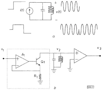
Fig. 1 Proposed configuration and experimental circuit
a Principle of this method h Experimental circuit
150811)
Principle and circuit description: A parallel LC resonant circuit and current source are shown in Fig. la. From circuit theory, if the excitation signal is a current step i(t) = Au(t), the voltage across the capacitor (or inductor) will be v(t) = (A/w~,c)sin(w~t)u(t). Using
this result and the superpositioii theory, when the excitation signal
is i(t) = Au(t)- Au(t-t(do,), the output voltage will be
where
,h
= 0,/2n: is the resonant frequency. This signal is also shown in Fig. l a and we can see that it is identical to a BPSK sig- nal. Therefore, we can employ this concept to design a BPSK modulator.Fig. lh depicts the novel BPSK modulator circuit. The VCCS, made by A , , Q, and R,, produces the N R Z current pulse stream and injects such a signal into the LC resonant circuit. If the reso- nant frequency,f;, is an integral time of the bit rate, the resonator output voltage will be a BPSK signal. Since the quality factor Q of a general purpose reactive inductor is < 100 and the transistors output resistance is finite, the voltage will decay as time passes. Because BPSK modulation is one kind of exponential modulation, it is immune to system nonlinearity. Therefore, by adding a com- parator or limiting amplifier following the resonator, we can coni- pensate for the amplitude decay and still maintain the phase reversal. Passing such a signal through a bandpass filter can pro- duce a filtered BPSK signal as in traditional modulation methods.
-
-
-
-
-
7
ch3
\
1
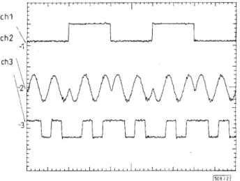
@Eg Fig. 2 Resultunt expcrinental waveforms
ch 1 : modulating signal vi ch 2: resonator output voltage v2
ch 3: comparator output voltage vj
const I -. -_ - _I
__
q
t.9 B6SsLEii I 90-
d J i-..
1 i d I L-1 @'r-
*.9 35BLL91-Fig. 3 S p e m u m of filteied BPSK rignul and demodulution output
U Signal constellation
b Modulator output 3pectrum following BPF
c Eye diagram of in-phase channel
d Eye diagram of qUddrdtUre-Chdnnel
Experiment result: Channel 1 in Fig. 2 is the modulating signal v, in Fig. lb; channel 2 is the resonator output voltage v,; channel 3 is the comparator o u t p u t voltage vj. W e find t h a t phase reversals occur at the transition or the modulation data bits. To appraise t h s modulator performance, we use a PN signal (with length 2IO-1) generated from a digital transmission analyser (Anritsu ME520A) as the modulating signal vl, and use a vector signal analyser (HP89441) to demodulate the BPSK signal from the switch-reso- nator BPSK modulator. Fig. 30 shows the signal constellation;
Fig. 3h shows the spectrum of the filtered BPSK signal (centre fre- quency 5MHz; bandwidth 2.5MHz). Fig. 3c is the eye diagram in the in-phase channel and Fig. 3d is the eye diagram in the quadra- ture-channel. This Figure shows that the signal generated from the switch-resonator BPSK modulator is correct.
Conclusion. A novel BPSK modulator has been implemented by using a current sourcc, an LC resonator and a comparator with- out an additional carrier signal, balanced modulator or phase shift circuit. This modulator is easy to assemble and its performance is acceptable. Except for the resonator, the VCCS and the limiting amplifier (or comparator) can be packaged in an IC and a high bit rate BPSK sigiial can be directly generated. It is suitable for gener- ating direct sequence spread spectrum (DSSS) signals in wireless communication.
2 June 1997 0 IEE 1997
Electronics Letteu Onlinc No: 19970885
Juin-Hung Chen and Hen-Wai Tsao (Room 213, Depurtnzent of
Electrical Enngincwinng, National Taiwim Uiziimyity, Tuipri, Tcziivan 107, Republic. of Chinu)
References
Harris Corporation: 'PC card wireless LAN handbook', 1996, pp.61 -62
YOUNG. P . H . : 'Electronics communication techniques' (Macmillan, New york, 1994)
MAZUMDER, S.R., and WATERMAN, R.C.: 'A novel 6 to 18GHZ 180" bit phase shifter configuration having very small amplitude and phase errors'. TEEE MTT-S Tnt. Microw. Symp. Dig., 1994, Vol. 1,
GOLDFARB. M.G , BRADFORD COLE, J., and P L x r m m , A : 'A novel MMIC biphase modulator with variable gain using enhancement- mode FETS suitable for 3 V wireless application'. IEEE Microw. and Millimetre-Wave Monolithic Circuit Symp., 1994, pp. 99-102
pp. 83-86
Correlation model for shadow fading in land-
mobile satellite systems
P. Taaghol and R. Tafazolli
Indexing ternis: Siztellite communication, Correlution nzethod,s
A simple yet accurate correlation model for shadow fading in land-mobile satellite systems, dcrived from L and S-band channel recordings, is proposed. The modcl has been developed for heavily wooded and suburban environments and covers elevation angles of 60-80". It is demonstrated that in such environments, the effective correlation distance of shadowing is in the order of a few tens of meters.
Irztroduction: Recently, there has been a great effort in the charac- terisation of the land-mobile satellite propagation channels, ena- bling the system design and dimensioning of the proposed satellite personal communication networks (S-PCN). Such experiments are very costly and time consuming. Consequently, unlike the terres- trial case, a very limited number of such campaigns have been car- ried out. The first-order (time-invariant) statistics of the land- mobile satellite propagation channel based on experimental results have been extensively reported in [ 11 and [2], however, the second- order (time-variant) statistics are generally much less well-known; corrclation statistics of shadow fading are one example, and have not yet been made available for satellite channels, restricting research [3] to only terrestrial values reported by [4]. An accurate correlation model for shadow fading in such enviroiiinents is of vital importance for both analytical and simulation based evalua- tion of any power control and handover scheme.
Channel recordings: The proposed shadow fading correlation model is based on the narrowband measurement campaign record- ings at L-band (1.3GHz) and S-band (2.3GHz), carried out by CCSR of University of Surrey in spring 1992 [l]. The measure-