Surface and bulk modes for periodic structures of negative index materials
Ruey-Lin Chern,1,2,*Chien C. Chang,2,1,† and C. Chung Chang21Institute of Applied Mechanics, National Taiwan University, Taipei 106, Taiwan, Republic of China
2Division of Mechanics, Research Center for Applied Sciences, Academia Sinica, Taipei 115, Taiwan, Republic of China 共Received 15 June 2006; revised manuscript received 10 August 2006; published 3 October 2006兲
In this paper, we investigate surface and bulk modes for periodic structures made of negative index materials in one and two dimensions. The negative index material is a composite medium consisting of a network of thin wires and a periodic array of split ring resonators. In different ranges of frequencies, we identify five types of modes: surface plasmon 共SP兲 modes for TE polarization, magnetic surface plasmon 共MSP兲 modes for TM polarization, trapped modes or resonant cavity modes for both TM and TE polarizations, asymmetric surface 共AS兲 modes for TE polarization, and some bulk modes for both polarizations in the range of negative material properties. In particular, we will discuss band flattening and broadening of SP and MSP modes, explain the trapped modes in terms of large positive dielectric constants, examine the properties of AS modes by an interface condition, and use the Rayleigh quotient to account for possibly infinite degeneracy of SP and MSP modes in two dimensions. All of the physical properties are computed by an interfacial operator approach in which we introduce an interfacial variable to measure the local strengths of various surface modes.
DOI:10.1103/PhysRevB.74.155101 PACS number共s兲: 42.70.Qs, 78.20.Bh, 02.70.⫺c, 02.70.Bf
I. INTRODUCTION
Materials with both negative electric permittivity and magnetic permeability have been proposed some 30 years ago by Veselago.1Unusual electromagnetic properties are
ex-pected due to the left handedness between the E, H fields and the wave vector k. Accordingly, the index of refraction n would be negative for these materials. However, there are no natural materials with negative permeability. Until recently, double negative materials共⬍0,⬍0兲 in an effective sense can be realized by Pendry et al. using a network of thin wires,2 combined with a periodic array of split ring
resonators.3This composite medium could be considered ho-mogeneous at wavelengths much larger than the size and spacing of the elements of the medium, and has an effective electric permittivity of the form
n共兲 = 1 −
p
2
2, 共1兲
wherep is the effective plasma frequency, and an effective
magnetic permeability of the form n共兲 = 1 −
F2 2−
0
2, 共2兲
where0is the resonant frequency of the split ring and F is the fractional area of the unit cell occupied by the interior of the split ring. The composite medium exhibits simulta-neously negative permittivity and permeability in the micro-wave regime, withp and0 in the GHz range.4 Recently, negative permeability has been realized in the 100 THz range.5 It must be noted that realistic double negative
metamaterials must be dispersive,4 otherwise the causality
constraint6will be violated. This is consistent with the
per-mittivity model共1兲 and permeability model 共2兲 of the
com-posite medium described above.
Because of its special format共2兲, the magnetic
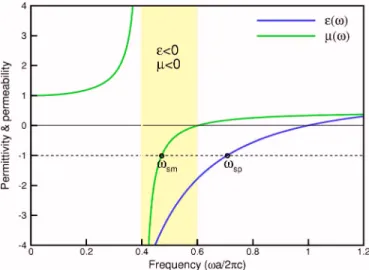
permeabil-ity bears some similarpermeabil-ity to the electric permittivpermeabil-ity, but has one particular point that is not shared by the latter. Figure1
shows the frequency dependence of the effective permittivity 共1兲 and permeability 共2兲. On the one hand, both have
nega-tive values in a range of frequencies: the electric permittivity is negative in 关0,p兴, while the magnetic permeability is
negative in关0,m兴, wherem=0/
冑
1 − F. Besides, bothnandnhave a zero crossing at the upper limit of the range:
the electric permittivity atpand the magnetic permeability
at m. On the other hand, the magnetic permeability turns
from positive to negative infinity in crossing the resonance frequency0. The present study is aimed to study the band structures of periodic structures made of negative index ma-terials, and in particular, we will investigate the conse-quences of the interplay between the electric permittivity and the magnetic permeability in different ranges of frequencies. In the simplest case of a planar interface between the negative index material and a material with positive
con-FIG. 1. 共Color online兲 The effective and of the negative index material forpa / 2c=1.0, 0a / 2c=0.4, and F=0.56. The yellow region corresponds to the frequency range where the me-dium has both negative and. The black circles denote the loca-tions ofspandsmford= 1 andd= 1.
sm=
冑
⬁ ⬁+d. 共4兲
In the case of an array of split ring resonators placed in a magnetic field, the induced currents flowing in the cylinders produce magnetization共magnetic polarization兲. It appears as if magnetic monopoles were flowing on opposite ends of the cylinders.7On a scale much larger than the size of split ring
resonators, the above phenomenon behaves like a magnetic plasma. Under suitable conditions, coupling of magnetic plasma with electromagnetic fields may give rise to MSP. It is noted that MSP have similar features of surface magnons 共SM兲 which can be found in ferromagnetic and antiferromag-netic materials.8–10 However, MSP and SM have different
physical origins, for SM waves come from the coupling of photons with electron spins, and tend to die out above GHz frequencies.5
It has been difficult to compute eigenmodes and band structures of frequency-dependent materials. The major dif-ficulty is due to a nonlinear formulation of the eigenvalue problem.11 Another difficulty comes from the highly
local-ized nature of the solutions, which is more evident for SP共or MSP兲 modes. Several approaches have been proposed to study the frequency-dependent problem, including plane wave expansion method,12transfer matrix method,13multiple
scattering theory or Korringa-Kohn-Rostoker 共KKR兲 method,14–16 layer-KKR method,17 finite-difference
time-domain method18and multiple multipole method.19Recently,
vectorial eigenmode expansion method20and cutting surface
method11 were also applied to this type of problem. In this
study, we will compute the various types of modes for one-dimensional as well as two-one-dimensional periodic structures made of negative index materials, and gives the detailed physical and mathematical account of the observed mode patterns. These modes will be computed in the framework of the interfacial operator approach, recently developed by the present authors.21,22
It is of general interest to see what happens to SP and MSP modes if the interface is not planar, or the interface is not a single plane, but is such complicated as in the periodic structures. Indeed, we will show that the patterns of the modes for periodic structures made of the negative index material with optical properties 共1兲 and 共2兲 can be divided
into five types共a兲 SP modes distributed aroundsp,共b兲 MSP modes distributed around sm, 共c兲 trapped modes or
reso-−1 ⵜ ·
冉
1 ⵜ E冊
=冉
c冊
2 E, 共5兲 − 1 ⵜ ·冉
1 ⵜ H冊
=冉
c冊
2 H 共6兲for TM and TE modes, respectively. For periodic structures, it is sufficient to solve the underlying problem on one unit cell along with Bloch’s condition as the boundary condition
E共r + ai兲 = eik·aiE共r兲, 共7兲
H共r + ai兲 = eik·aiH共r兲, 共8兲
where k is the wave vector and ai 共共i=1,2兲 are the lattice
translation vectors. The resultant eigensystem for Eqs. 共5兲
and共6兲 can be written as
L共⌳兲=⌳, 共9兲
where⌳=2/ c2is the eigenvalue andis the eigenfunction which can be either the E or H field. For frequency-dependent materials, the eigensystem 共9兲 no longer has a
standard format since the eigenvalue itself appears in the differential operator. If Eq.共9兲 is solved by discretizing it in
a straightforward manner, for example, by a finite-difference scheme, we will obtain a nonlinear eigensystem
A共⌳兲x = ⌳x, 共10兲
where A is the matrix system, and x is the eigenvector. This is one type of nonlinear eigenvalue problem, that is, nonlin-ear in eigenfrequency. However, if both the permittivity and permeability of the material have analytical forms, we are able to reformulate the original nonlinear eigenvalue prob-lem as a standard one.
In our previous studies,21,22we have proposed the interfa-cial operator approach to compute surface plasmon modes for periodic structures made of dispersive metals as well as polar materials. In this paper, we extend this approach to be applicable to negative index materials with the effective per-mittivity model共1兲 and permeability model 共2兲.
The basic idea is first to deal with the eigensystems共5兲
and共6兲 in the strict insides of the dielectric and the negative
of the operator in either region. In the strict inside of the dielectric,
−ⵜ2E =dd⌳E, 共11兲
−ⵜ2H =
dd⌳H, 共12兲
where d and d are the permittivity and permeability,
re-spectively, of the surrounding dielectric material. In the strict inside of the negative index material,
−ⵜ2E = ⬁共⌳ − ⌳p兲
冉
⌳ − ⌳m ⌳ − ⌳0冊
E, 共13兲 −ⵜ2H =⬁共⌳ − ⌳p兲冉
⌳ − ⌳m ⌳ − ⌳0冊
H, 共14兲 where⌳p=p 2 / c2,⌳0=0 2 / c2, and ⌳m=m 2 / c2. Here, ⬁= 1 − F is the high frequency limit of the effective permeability, and m=0/冑
1 − F is the effective magnetic plasma fre-quency. Equations共13兲 and 共14兲 can be further rearranged as⌳2E −⌳L 1E + L2E = 0, 共15兲 ⌳2H −⌳L 1H + L2H = 0, 共16兲 where L1=⌳p+⌳m− 1 ⬁ⵜ 2, L 2=⌳p⌳m− ⌳0 ⬁ⵜ 2. 共17兲 Equations 共11兲, 共13兲, 共12兲, and 共14兲 are connected,
respec-tively, by the interface conditions
冉
1 E n冊
S = 0,冉
1 H n冊
S = 0, 共18兲where/n denotes the derivative in the surface normal
di-rection, and 关¯兴S the jump across the interface S between
the dielectric and the negative index material. The interface conditions共18兲 are obtained by integrating both sides of the
eigensystem共5兲 and 共6兲 over a thin box located on the
inter-face, and taking the limit as the box height goes to zero. Applying the permittivity and permeability models 共1兲 and
共2兲, the interface conditions 共18兲 are rearranged as
⌳m d
冏
E n冏
+ − ⌳0 ⬁冏
E n冏
− =⌳SE, 共19兲 ⌳p d冏
H n冏
+=⌳SH 共20兲so that the eigenvalue⌳ appears only on the right-hand side, where SE⬅ 1 d
冏
E n冏
+ − 1 ⬁冏
E n冏
− , 共21兲 SH⬅冏
1 d H n冏
+−冏
H n冏
− 共22兲are the weighted differences of the normal derivatives of the
E and H fields, respectively, across the interface, with⫹ and
⫺ denoting the dielectric and the negative index material sides, respectively.
Apparently, Eqs.共11兲 and 共15兲, supplemented by Eq. 共19兲,
cannot be formulated as a standard eigensystem in terms of the E field, for the right-hand sides of Eqs. 共19兲 and 共20兲
contain the derivatives of E or H field. Likewise, Eqs.共12兲,
共16兲, and 共20兲 cannot be formulated as a standard
eigensys-tem for the H field either. Nevertheless, this difficulty can be removed by employing the interfacial operator approach in finite difference formulation.21,22 With this approach, the
eigensystem共10兲 can be recast into the following form:
共⌳2−⌳B − C兲y = 0, 共23兲
and thus further reduced to
冋
0 I C B册冋
y y⬘
册
=⌳冋
y y⬘
册
, 共24兲where y
⬘
=⌳y, B and C are constant matrices. The eigensys-tem 共24兲 can be solved by standard eigenvalue solvers, andhas the same eigenvalue⌳ as the original eigensystem 共10兲,
although the new eigenvector y is slightly different from the original eigenvector x. However, they can be converted back and forth between each other.
III. RESULTS AND DISCUSSION
The primary interest of the present study is to understand the interplay between the effective electric permittivity⑀and magnetic permeability . The interplay consists mainly of the product⑀, as suggested by Eqs.共11兲 and 共12兲 for the
dielectric, Eqs.共13兲 and 共14兲 for the negative index material,
and the interface conditions between them, dictated in Eqs. 共19兲 and 共20兲. In the present study, we use the following
parameters for the permittivity 共1兲 and permeability 共2兲:
p/ 2= 10101 / s, 0/ 2= 4⫻1091 / s, and F = 0.56, which are in the same range as in Ref.4. In nondimensional units, we choose pa / 2c = 1 and 0a / 2c = 0.4 for the lattice constant a = 3 cm. It follows that ma / 2c = 0.603 and ⬁
= 1 − F = 0.44.
A. One-dimensional structures
Surface plasmon modes. SP modes have been studied for
a semi-infinite metal and a metal slab.23 For periodic
struc-tures, SP modes have also been investigated for photonic crystals made of dispersive metals.18,19,21,24 On the other hand, MSP modes were reported for a left-handed material of a semi-infinite plane and a slab.25,26In this study, we present
MSP modes for periodic structures made of negative index materials. Figure2shows the dispersion relation at the zone edge 共ka/2= 0.5兲 for one-dimensional layered structures with thickness ratio t / a = 0.2. It is shown that in addition to two branches of SP modes for TE polarization with frequen-cies approaching the surface plasma frequency sp 关cf. Eq. 共3兲兴 at large off-line wave number共component of the wave
number parallel to the interface兲, there are two branches of MSP modes for TM polarization with frequencies approach-ing the magnetic surface plasma frequencysm关cf. Eq. 共4兲兴. It is noted that the asymptotic frequencies of SP or MSP
modes for periodic structures is the same as for a semi-infinite plane and a slab.23,25,26Ford= 1 andd= 1, we have
spa / 2c = 0.7071 and sma / 2c = 0.4714, the locations of which are denoted by black circles in Fig.1. Note also that sm is located in the range0⬍⬍m where bothn and
n are negative, and the composite medium is left handed.
Besides, the higher band of MSP modes has a negative group velocity over the whole range of. Figure3 shows the dis-persion relation for the thickness ratio t / a = 0.8. It is shown that for a larger fraction of the negative index material, the frequency of the higher band of SP modes begins with the bulk plasma frequency p at = 0 and approaches sp at large, with a relatively large value of negative group ve-locity. Both Figs.2and3show that all the modes to the right of the light line will become surface modes共approachingsp or sm兲 or RC modes 共approaching 0 from above兲 at the large limit of. It is therefore expected that for large off-line wave number, propagation of the electromagnetic waves is prohibited except for the frequencies near three resonant fre-quencies0,sp, andsm.
Asymmetric surface modes. In addition to the two pairs of
SP and MSP modes, Fig. 2 also shows two branches of asymmetric surface共AS兲 modes for TE polarization with fre-quencies approaching the resonant frequency0from below. This is in contrast to the branches of SP or MSP modes with frequencies approaching sp or sm from both above and below. Figure4shows two AS modes ata / 2= 1 and two AS modes ata / 2= 2 for TE polarization at the zone
cen-ter 共k=0兲. The eigenfrequencies of the two AS modes ap-proach the asymptotic frequency0much faster than for SP or MSP modes. This type of surface modes appear only for TE polarization, which is consistent with the observation for the cases of a semi-infinite plane25 and a slab.26 Note also
that the field decays much more rapidly inside the negative index material than outside. This can be understood from the interface condition at=0,
冏
H n冏
−= −冏
冉
p 2 −02 d0 2冊
H n冏
+. 共25兲In the present case, the slope of the H field共at the interface兲 on the side of the negative index material is 5.25 关共p2
−02兲/d02= 5.25兴 times that on the dielectric side. This is
the reason why these surface modes are said to be asymmet-ric. Existence of AS modes can be further explained through
the dispersion relation of surface modes for TE polarization in a more general form27
= c
冉
dn共dn−nd兲 d 2 −n 2冊
1/2 . 共26兲Substitutingnandnwith Eqs.共1兲 and 共2兲 for the negative
index material and taking the limit→⬁, we obtain FIG. 2. 共Color online兲 The dispersion relations at ka/2=0.5
for a one-dimensional layered structure of negative index material of thickness t / a = 0.2 wherepa / 2c=1.0, 0a / 2c=0.4, and F = 0.56.
FIG. 3. 共Color online兲 The dispersion relations at ka/2=0.5 for a one-dimensional layered structure of negative index material of thickness t / a = 0.8 wherepa / 2c=1.0, 0a / 2c=0.4, and F = 0.56.
共d 2− 1兲6+关2 p 2 −共d 2− 1兲 0 2兴4− p 2共 p 2 + 202兲2 +p402= 0. 共27兲
The above equation can be solved to yield the asymptotical solutions→sp=p/
冑
1 +d as well as→0.Resonant cavity modes. Refer again to Figs.2and3. In a small range lying immediately above the resonant frequency 0,nnbecomes very large and the negative index material
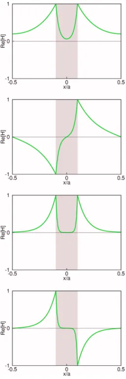
behaves like a cavity filled with a medium of very large refractive index. Most of the fields are trapped in the nega-tive index material, and a large number of branches of bulk modes, called resonant cavity 共RC兲 modes, are intensively gathering around the resonant frequency0 from above for both TM and TE polarizations. For a large fraction of the negative index material, there are even more RC modes with most of the fields being concentrated inside the medium. Figure5 shows four typical RC modes for TM polarization witha / 2c = 0.4 at the zone center共k=0兲 and= 0 for the
thickness ratio t / a = 0.4. These mode structures have strong oscillatory patterns in the negative index material and nearly null fields outside. A similar feature is also observed for TE polarization. In fact, these modes resemble the RC modes in photonic crystals made of polar materials.20
B. Two-dimensional structures
Infinite degeneracy. First of all, we are concerned with the
grid resolution. Figure 6shows the distribution of eigenfre-quencies for TE modes for a square array of square cylinders of negative index material with half-width w / a = 0.2. It is shown that the frequencies are little dependent on the grid level except in two distinct regions: one below the resonant frequency0共RC modes兲 and one around the surface plasma frequency sp 共SP modes兲. As expected, the modes inten-sively distributed above 0 are the RC modes. However, contrary to the one-dimensional structures that have only two branches of SP modes, the two-dimensional crystals appar-ently have an infinite number of SP modes gathering around the surface plasma frequencysp. The same figure seems to indicate that the number of resolved SP modes共RC modes兲 increases linearly 共quadratically兲 with the number of grid points. In fact, existence of an infinite number of resonant modes can be inferred from the three-dimensional polaritonic photonic crystals28and perfect corner reflectors.29Likewise,
for TM polarization, we have also observed the same behav-ior for MSP modes as well as RC modes. This point will be further discussed in the next section through the Rayleigh quotient of the eigensystem with the help of the interfacial variable.
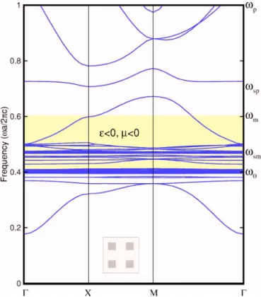
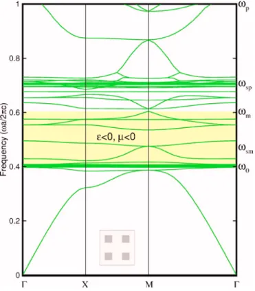
Figures 7 and 8 show the band structures for a square array of square cylinders of negative index material with half-width w / a = 0.1. For the negative index material with the effective permittivity 共1兲 and permeability 共2兲, a large
number of frequency bands gathering around sp occur for TE polarization. These resonant bands also occur in metall-odielectric photonic crystals,30–32 which result from the strong photon-electron coupling. In the meanwhile, a large number of frequency bands occur also for TM polarization. The latter consist of branches of MSP modes gathering around the magnetic surface plasma frequencysm, and the typical feature of resonant TM bands is similar to that of resonant TE bands. For TM polarization, there are no surface modes observed around the frequencysp, while for TE po-larization there are no surface modes observed around the FIG. 4. 共Color online兲 Two AS modes with a/2c=0.3968
and 0.3971 at the off-line wave numbera/2=1 共upper figures兲, and two AS modes witha/2c=0.3996 ata/2=2 共lower fig-ures兲 for TE polarization at the zone center 共k=0兲 for a one-dimensional layered structure of negative index material of thick-ness t / a = 0.2 wherepa / 2c=1.0, 0a / 2c=0.4, and F=0.56.
frequencysm. On the other hand, bulk modes are allowed in the frequency range with ⑀n⬍0 and n⬍0 because the
equivalent permittivity or permeability ⑀nn is positive. A
similar periodic structure of two-dimensional checkerboard consisting of alternating positive and negative index materi-als was recently shown to possess peculiar imaging properties.33
It is of interest to see what happens if the negative index material is made thin and connected. For this purpose, Figs.
9and10show the band structures for a square array of grid cylinders with thickness t / a = 0.2. Compared to Fig. 7, the TM bands for thin grid structures spread more widely around sm than for square cylinders. On the other hand, the TE bands for thin grid structures spread more widely aroundsp than for square cylinders. The band broadening corresponds to the degeneracy lifting of SP and MSP modes, which more easily appear in thin structures due to effective interaction of the modes on both sides of the structure. On the other hand,
FIG. 5. 共Color online兲 Four typical RC modes for TM polariza-tion witha/2c=0.4 at the zone center 共k=0兲 with=0 for a one-dimensional layered structure of negative index material of thickness t / a = 0.4 where pa / 2c=1.0, 0a / 2c=0.4, and F = 0.56.
FIG. 6.共Color online兲 The eigenfrequencies for TE modes ver-sus the index of eigenmode computed with different grid resolutions at the point⌫ for a square array of square cylinders of half width
w / a = 0.2 wherepa / 2c=1.0, 0a / 2c=0.4, and F=0.56.
FIG. 7. 共Color online兲 The TM band structures for a square array of square cylinders of negative index material with half-width
connectivity of the structure allows existence of zero-frequency modes, in particular, for TE polarization for all wave vectors, and thus a zero-order band gap similar to the cutoff frequency in TM polarization is observed. These two points have also been discussed in Ref.24for photonic crys-tals of dispersive mecrys-tals.
Figures11 and12show four typical SP modes in magni-tude for TE polarization and four typical MSP modes for TM polarization with frequencies nearspandsm, respectively. The fields are represented by a color level from blue to red indicating the magnitude from zero to the maximum unity, and the black line denotes the boundary of the negative index material. A very sharp feature of the field pattern near the interface is observed for SP modes as well as MSP modes. Different variations of the fields along the interface account for the high degeneracy around sp or sm, and an infinite number of SP or MSP modes would be expected.
Resonant cavity modes. Next, we consider the RC modes
with frequencies lying immediately above the resonant fre-quency0. In Figs.7–10, even more flattened bands for both TE and TM modes gathering around0 from above are ob-served. This is analogous to the one-dimensional case, and these modes have similar properties of RC modes that appear in two-dimensional polaritonic crystals.20 Figure 13 shows
four typical RC modes in magnitude for TE polarization with frequencies near 0 at the point ⌫ for a square array of square cylinders of half-width w / a = 0.3.
These bulk modes correspond to very large dielectric con-stants wherenn→⬁ as the frequency approaches0from above. This is consistent with the resonances of the square FIG. 9. 共Color online兲 The TM band structures for a square
array of grid cylinders of negative index material with the thickness ratio t / a = 0.1, wherepa / 2c=1.0, 0a / 2c=0.4, and F=0.56.
FIG. 8.共Color online兲 The TE band structures for a square array of square cylinders of negative index material with half-width
w / a = 0.2, wherepa / 2c=1.0, 0a / 2c=0.4, and F=0.56.
FIG. 10. 共Color online兲 The TE band structures for a square array of grid cylinders of negative index material with the thickness ratio t / a = 0.1, wherepa / 2c=1.0, 0a / 2c=0.4, and F=0.56.
cavity or the metallic waveguide modes with frequencieskl
determined by two free indices k and l34
kl= c 2w
冑
klkl冑
k2+ l2, 共28兲 where kl= 1 −p 2 /kl 2 and kl=共1−F兲共kl 2 −m 2兲共 kl 2 −02兲. Solving Eq.共28兲 for klyieldskl 2 = 2kl ␣kl+
冑
␣kl2 − 4kl , 共29兲 where ␣kl=p2+m2+⍀kl2, kl=⍀kl202+p2m2, and ⍀kl=c
冑
k2+ l22w冑
1 − F with w the half-width of the square cav-ity. The expression共29兲 indicates that0 is the lower limit frequency of RC modes for if ⍀kl goes to infinity, klap-proaches 0. On the other hand, if ⍀kl goes to 0, kl
ap-proaches 关m2−⍀kl2共m2−02兲/共p2−m2兲兴1/2. Therefore, for a
FIG. 11. 共Color online兲 Four typical SP modes in magnitude for TE polarization with frequencies nearspat the point⌫ for a square array of square cylinders of negative index material of half-width w / a = 0.3 wherepa / 2c=1.0, 0a / 2c=0.4, and F=0.56.
larger fraction of the negative index material, that is, large value of w / a, the resonant bands spread more widely.
Asymmetric surface modes. As in the case of the
one-dimensional structures, at the interface the asymmetric sur-face共AS兲 mode decays 5.25 times faster inside the negative index material than outside关cf. Eq. 共25兲兴. The present grid
resolution shows that the frequency range of AS modes is highly concentrated on a very narrow region lying immedi-ately below the resonance frequency0 where the product ⑀nnis largely negative. It is therefore expected that the
ma-terial with negative⑀nn effectively expells the fields,
pre-senting itself like a mask region. Finer grid resolutions show
that the number of AS modes increases with increasing the number of grid points. This is in contrast to only two such modes in one-dimensional structures, and there might be an infinite number of AS modes in two dimensions. The field pattern of AS modes with different variations along the in-terface may be responsible for possible infinite degeneracy. Comparison between Figs.8 and 10shows that the thinner negative index material allows effective broadening of SP and MSP modes, but not AS modes. This is because the more rapidly decaying rate of the AS modes in the negative index material does not allow overlap of the field on opposite sides of the material, and therefore has no effect in lifting their FIG. 12.共Color online兲 Four typical MSP modes in magnitude for TM polarization with frequencies nearspat the point⌫ for a square array of square cylinders of negative index material of half-width w / a = 0.3 wherepa / 2c=1.0, 0a / 2c=0.4, and F=0.56.
degeneracy. It must also be noted that in the surrounding dielectric medium, the field of an AS mode in magnitude does diminish monotonically共rather than exhibit an oscilla-tory pattern兲 as the distance from the interface is increased. The four AS modes shown in Fig.14have different degrees of oscillation along the interface, and in general the mode with a higher degree decays more rapidly away from the interface than that with a lower degree.
The frequency ranges of the various modes described above are conveniently summarized in TableI.
C. Interfacial variable
In the present approach, the interfacial variables SEin Eq.
共21兲 and SH in Eq. 共22兲 are introduced to be the weighted
differences of the normal derivatives of the E and H fields, respectively, on two sides of the interface. These variables serve as a measure of the local strengths of SP or MSP modes at the interface, and their meanings can be further manifest through the formulations of the Rayleigh quotients for the eigensystems共5兲 and 共6兲. It is known that the
eigen-frequency corresponds to minimization of the Rayleigh quo-FIG. 13. 共Color online兲 Four typical RC modes in magnitude for TM polarization with frequencies near0at the point⌫ for a square array of square cylinders of negative index material of half-width w / a = 0.3 wherepa / 2c=1.0, 0a / 2c=0.4, and F=0.56.
tient under the constraint that the corresponding eigenfunc-tion be orthogonal to all previously obtained eigenfunceigenfunc-tions. The Rayleigh quotient for a standard eigensystemL=⌳, is given by
R= 具,L典
具,典 , 共30兲
where具f ,g典=兰Vcellf*gddenotes the inner product of f and g
over the unit cell Vcell. For a linear operatorL, Eq. 共30兲 can be used directly, while for a nonlinear operator, the Rayleigh
FIG. 14.共Color online兲 Four typical AS modes in magnitude for TE polarization with frequencies near0at the point⌫ for a square array of square cylinders of negative index material of half-width w / a = 0.3 wherepa / 2c=1.0, 0a / 2c=0.4, and F=0.56.
TABLE I. Various modes for TM and TE polarizations for dif-ferent optical properties.
Optical constants TM polarization TE polarization
⬇sp SP modes
⬇sm MSP modes
⬍0,⬇−⬁ RC modes RC modes
⬍0,⬇ +⬁ AS modes
dratic expression of the Rayleigh quotient RH, RH 2 A − RHB + C = 0, 共33兲 or, equivalently, RH= B ±
冑
B2− 4AC 2A , 共34兲 where A =d冕
Vd 兩H兩2d+ ⬁冕
Vn 兩H兩2d, B =冕
Sn H*SHda + 1 d冕
Vd 兩ⵜH兩2d+冕
Vn 关兩ⵜH兩2 +⬁共⌳p+⌳m兲兩H兩2兴d, C = −⌳0冕
Sn H*冏
H n冏
− da +⌳0冕
Vn 兩ⵜH兩2d +⬁⌳p⌳m冕
Vn 兩H兩2d,with Vdand Vndenoting the volumes of the dielectric and the
negative index material, respectively, of the unit cell, and Sn
denoting the surface of Vn. In the expression of B, the
inter-facial variable SH⬅兩
1 d
H
n兩+−兩Hn兩− 关cf. Eq. 共22兲兴 appears in the surface integral term, which accounts for the contribution of the strength of SP mode to the eigenfrequency. Note also that only the normal derivative of the H field共H /n兲 occurs
in the surface integral, and therefore tangential variation of the H field will not change the value of RH as well as the
eigenfrequency. This can be used to explain the highly de-generate nature of SP modes, that is, a large number of dif-ferent patterns of SP modes possessing an identical oscilla-tion frequency共see also Refs.21and24兲.
Likewise, the eigensystems共11兲 and 共15兲 for TM modes
in the dielectric and the negative index material, respectively, are rewritten as ⌳2共 dE兲 + ⌳
冉
1 d ⵜ2E冊
= 0, 共35兲冕
Sn E d冕
Vd 兩ⵜE兩 +冕
Vn冉
1 ⬁兩ⵜE兩 2+共⌳ p+⌳m兲兩E兩2冊
d, G = −⌳0 ⬁冕
Sn E*冏
E n冏
−da + ⌳0 ⬁冕
Vn 兩ⵜE兩2d +⌳p⌳m冕
Vn 兩E兩2d.In the expression of F, the interfacial variable SE⬅
1 d兩 E n兩+ −1 ⬁兩 E
n兩− 关cf. Eq. 共21兲兴 appears in the surface integral term, which accounts for the contribution of the strength of MSP mode to the eigenfrequency.
A close inspection of the derivations of Eqs.共33兲 and 共37兲
reveals that all the three terms in C or G are contributed exclusively by the negative index material. The singly most significant difference between the two Rayleigh quotients is the appearance of SHin B for TE modes, and SEin F for TM
modes. The close resemblance between SE and SH in the
expressions of the Rayleigh quotients also explains the exis-tence of a magnetic analog of SP modes for TM polarization. In this regard, the interfacial variable SHor SE is not only
introduced to be an auxiliary variable for solving the eigen-frequency, but also serves as a quantitative measure to the strength of SP or MSP mode. It is also noted that in the
expression of the Rayleigh quotients RHand RE, only normal
derivatives of the fields are incorporated in the integrals, and variation of the fields along the interface will not change the value of the Rayleigh quotient well as the eigenfrequency. Therefore, the interface can sustain, in principle, an infinite number of degenerate modes.
IV. CONCLUDING REMARKS
In conclusion, we have computed the band structures and various surface modes for periodic structures made of nega-tive index materials by the interfacial operator approach. It was shown that all the differences between TE and TM modes consist in the different interface conditions which are employed to formulate the interfacial operator approach. The crucial step is the introduction of the interfacial variable at
the interface between the negative index material and the surrounding dielectric medium. The interfacial variable leads to a finite difference formulation for transforming the appar-ently nonlinear eigenvalue problem for the eigenmodes and eigenfrequencies to a quadratic eigenvalue problem, which is further reduced to a linear eigensystem.
In different ranges of frequencies, we have identified five types of modes: 共a兲 SP modes distributed around sp, 共b兲 MSP modes distributed aroundsm,共c兲 trapped modes or RC modes lying immediately above0,共d兲 AS modes lying im-mediately below0, and共e兲 other bulk modes in the range of negative material properties. The SP and MSP modes, re-spectively, are pertaining to individual negative electric per-mittivity and negative magnetic permeability. In contrast, the RC modes and the AS modes are closely associated with the large positive product⑀nnand large negative product ⑀nn
near the resonance frequency0. The present grid resolution indicates that there is possibly an infinite number of SP,
MSP, and AS modes in two dimensions. The distinctions between SP, MSP, and AS modes were examined by the in-terface conditions and the Rayleigh quotients, which also help explain the infinite degeneracy of these surface modes. It was also shown that the thinner negative index material allows effective broadening of SP and MSP modes, but not AS modes. This is because the more rapidly decaying rate of the AS modes in the negative index material does not allow overlap of the field on opposite sides of the material, and therefore has no effect in lifting their degeneracy.
ACKNOWLEDGMENTS
This work was supported in part by National Science Council of the Republic of China under Contracts Nos. NSC 94-2212-E-002-047 and NSC 94-2212-E-002-076, and the Ministry of Economic Affairs of the Republic of China under Contract No. MOEA 95-EC-17-A-08-S1-0006.
*Electronic address: chern@iam.ntu.edu.tw †Electronic address: mechang@gate.sinica.edu.tw
1V. G. Veselago, Sov. Phys. Usp. 10, 509共1968兲.
2J. B. Pendry, A. J. Holden, D. J. Robbins, and W. J. Stewart, J. Phys.: Condens. Matter 10, 4785共1998兲.
3J. B. Pendry, A. J. Holden, D. J. Robbins, and W. J. Stewart, IEEE Trans. Microwave Theory Tech. 47, 2075共1999兲. 4D. R. Smith and N. Kroll, Phys. Rev. Lett. 85, 2933共2000兲. 5S. Linden, C. Enkrich, M. Wegener, J. Zhou, T. Koschny, and C.
M. Soukoulis, Science 306, 1351共2004兲.
6L. D. Landau, E. M. Lifshitz, and L. P. Pitaevskii,
Electrodynam-ics of Continuous Media, 2nd ed.共Butterworth-Heinenann,
Ox-ford, 1984兲.
7J. B. Pendry and S. O’Brien, J. Phys.: Condens. Matter 14, 7409 共2002兲.
8A. Hartstein, E. Burstein, A. A. Maradudin, R. Brewer, and R. F. Wallis, J. Phys. C 6, 1266共1973兲.
9R. E. Camley and D. L. Mills, Phys. Rev. B 26, 1280共1982兲. 10M. R. F. Jensen, S. A. Feiven, T. J. Parker, and R. E. Camley,
Phys. Rev. B 55, 2745共1997兲.
11O. Toader and S. John, Phys. Rev. E 70, 046605共2004兲. 12V. Kuzmiak, A. A. Maradudin, and A. R. McGurn, Phys. Rev. B
55, 4298共1997兲.
13M. M. Sigalas, C. M. Soukoulis, C. T. Chan, and K. M. Ho, Phys. Rev. B 49, 11080共1994兲.
14A. Moroz, J. Phys.: Condens. Matter 6, 171共1994兲. 15A. Moroz, Phys. Rev. B 51, 2068共1995兲.
16A. Moroz and A. Tip, Phys. Lett. A 235, 195共1997兲.
17A. Modinos, N. Stefanou, and V. L. Yannopapas, Opt. Express 8, 197共2001兲.
18T. Ito and K. Sakoda, Phys. Rev. B 64, 045117共2001兲. 19E. Moreno, D. Erni, and C. Hafner, Phys. Rev. B 65, 155120
共2002兲.
20K. C. Huang, P. Bienstman, J. D. Joannopoulos, K. A. Nelson, and S. Fan, Phys. Rev. Lett. 90, 196402共2003兲.
21C. C. Chang, R. L. Chern, C. C. Chang, and R. R. Hwang, Phys. Rev. B 72, 205112共2005兲.
22R. L. Chern, C. C. Chang, and C. C. Chang, Phys. Rev. B 73, 235123共2006兲.
23H. Raether, Surface Plasmons on Smooth and Rough Surfaces
and on Gratings共Springer-Verlag, Berlin, 1988兲.
24R. L. Chern, C. C. Chang, and C. C. Chang, Phys. Rev. E 73, 036605共2006兲.
25R. Ruppin, Phys. Lett. A 277, 61共2000兲.
26R. Ruppin, J. Phys.: Condens. Matter 13, 1811共2001兲.
27S. Darmanyan, M. Neviére, and A. Zakhidov, Opt. Commun.
225, 233共2003兲.
28G. Gantzounis and N. Stefanou, Phys. Rev. B 72, 075107共2005兲. 29S. Guenneau, B. Gralak, and J. Pendry, Opt. Lett. 30, 1204
共2005兲.
30A. Moroz, Phys. Rev. Lett. 83, 5274共1999兲.
31H. van der Lem and A. Moroz, J. Opt. A, Pure Appl. Opt. 2, 395 共2000兲.
32H. van der Lem, A. Tip, and A. Moroz, J. Opt. Soc. Am. B 20, 1334共2003兲.
33S. Guenneau, A. Vutha, and S. Ramakrishna, New J. Phys. 7, 164 共2005兲.
34K. C. Huang, P. Bienstman, J. D. Joannopoulos, K. A. Nelson, and S. Fan, Phys. Rev. B 68, 075209共2003兲.