2002 Springer-Verlag London Limited
An Analysis of Draw-Wall Wrinkling in a Stamping Die Design
F.-K. Chen and Y.-C. Liao
Department of Mechanical Engineering, National Taiwan University, Taipei, Taiwan
Wrinkling that occurs in the stamping of tapered square cups and stepped rectangular cups is investigated. A common characteristic of these two types of wrinkling is that the wrinkles are found at the draw wall that is relatively unsup-ported. In the stamping of a tapered square cup, the effect of process parameters, such as the die gap and blank-holder force, on the occurrence of wrinkling is examined using finite-element simulations. The simulation results show that the larger the die gap, the more severe is the wrinkling, and such wrinkling cannot be suppressed by increasing the blank-holder force. In the analysis of wrinkling that occurred in the stamping of a stepped rectangular cup, an actual production part that has a similar type of geometry was examined. The wrinkles found at the draw wall are attributed to the unbalanced stretching of the sheet metal between the punch head and the step edge. An optimum die design for the purpose of eliminating the wrinkles is determined using finite-element analysis. The good agreement between the simulation results and those observed in the wrinkle-free production part validates the accuracy of the finite-element analysis, and demonstrates the advantage of using finite-element analysis for stamping die design.
Keywords: Draw-wall wrinkle; Stamping die; Stepped
rec-tangular cup; Tapered square cups
1.
Introduction
Wrinkling is one of the major defects that occur in the sheet metal forming process. For both functional and visual reasons, wrinkles are usually not acceptable in a finished part. There are three types of wrinkle which frequently occur in the sheet metal forming process: flange wrinkling, wall wrinkling, and elastic buckling of the undeformed area owing to residual elastic compressive stresses. In the forming operation of stamp-ing a complex shape, draw-wall wrinklstamp-ing means the occurrence
Correspondence and offprint requests to: Professor F.-K. Chen,
Depart-ment of Mechanical Engineering, National Taiwan University, No. 1 Roosevelt Road, Sec. 4, Taipei, Taiwan 10617. E-mail: fkchen얀 w3.me.ntu.edu.tw
of wrinkles in the die cavity. Since the sheet metal in the wall area is relatively unsupported by the tool, the elimination of wall wrinkles is more difficult than the suppression of flange wrinkles. It is well known that additional stretching of the material in the unsupported wall area may prevent wrinkling, and this can be achieved in practice by increasing the blank-holder force; but the application of excessive tensile stresses leads to failure by tearing. Hence, the blank-holder force must lie within a narrow range, above that necessary to suppress wrinkles on the one hand, and below that which produces fracture on the other. This narrow range of blank-holder force is difficult to determine. For wrinkles occurring in the central area of a stamped part with a complex shape, a workable range of blank-holder force does not even exist.
In order to examine the mechanics of the formation of wrinkles, Yoshida et al. [1] developed a test in which a thin plate was non-uniformly stretched along one of its diagonals. They also proposed an approximate theoretical model in which the onset of wrinkling is due to elastic buckling resulting from the compressive lateral stresses developed in the non-uniform stress field. Yu et al. [2,3] investigated the wrinkling problem both experimentally and analytically. They found that wrinkling could occur having two circumferential waves according to their theoretical analysis, whereas the experimental results indi-cated four to six wrinkles. Narayanasamy and Sowerby [4] examined the wrinkling of sheet metal when drawing it through a conical die using flat-bottomed and hemispherical-ended punches. They also attempted to rank the properties that appeared to suppress wrinkling.
These efforts are focused on the wrinkling problems associa-ted with the forming operations of simple shapes only, such as a circular cup. In the early 1990s, the successful application of the 3D dynamic/explicit finite-element method to the sheet-metal forming process made it possible to analyse the wrinkling problem involved in stamping complex shapes. In the present study, the 3D finite-element method was employed to analyse the effects of the process parameters on the metal flow causing wrinkles at the draw wall in the stamping of a tapered square cup, and of a stepped rectangular part.
A tapered square cup, as shown in Fig. 1(a), has an inclined draw wall on each side of the cup, similar to that existing in a conical cup. During the stamping process, the sheet metal on the draw wall is relatively unsupported, and is therefore
Fig. 1. Sketches of (a) a tapered square cup and (b) a stepped rectangular cup.
prone to wrinkling. In the present study, the effect of various process parameters on the wrinkling was investigated. In the case of a stepped rectangular part, as shown in Fig. 1(b), another type of wrinkling is observed. In order to estimate the effectiveness of the analysis, an actual production part with stepped geometry was examined in the present study. The cause of the wrinkling was determined using finite-element analysis, and an optimum die design was proposed to eliminate the wrinkles. The die design obtained from finite-element analy-sis was validated by observations on an actual production part.
2.
Finite-Element Model
The tooling geometry, including the punch, die and blank-holder, were designed using the CAD program PRO/ ENGINEER. Both the 3-node and 4-node shell elements were adopted to generate the mesh systems for the above tooling using the same CAD program. For the finite-element simul-ation, the tooling is considered to be rigid, and the correspond-ing meshes are used only to define the toolcorrespond-ing geometry and
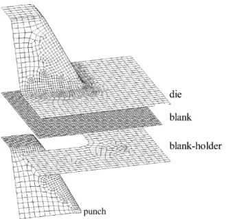
Fig. 2. Finite-element mesh.
are not for stress analysis. The same CAD program using 4-node shell elements was employed to construct the mesh system for the sheet blank. Figure 2 shows the mesh system for the complete set of tooling and the sheet-blank used in the stamping of a tapered square cup. Owing to the symmetric conditions, only a quarter of the square cup is analysed. In the simulation, the sheet blank is put on the blank-holder and the die is moved down to clamp the sheet blank against the blank-holder. The punch is then moved up to draw the sheet metal into the die cavity.
In order to perform an accurate finite-element analysis, the actual stress–strain relationship of the sheet metal is required as part of the input data. In the present study, sheet metal with deep-drawing quality is used in the simulations. A tensile test has been conducted for the specimens cut along planes coinciding with the rolling direction (0°) and at angles of 45° and 90° to the rolling direction. The average flow stress , calculated from the equation ⫽ (0⫹ 245⫹ 90)/4, for each measured true strain, as shown in Fig. 3, is used for the simulations for the stampings of the tapered square cup and also for the stepped rectangular cup.
All the simulations performed in the present study were run on an SGI Indigo 2 workstation using the finite-element pro-gram PAMFSTAMP. To complete the set of input data required
for the simulations, the punch speed is set to 10 m s⫺1and a coefficient of Coulomb friction equal to 0.1 is assumed.
3.
Wrinkling in a Tapered Square Cup
A sketch indicating some relevant dimensions of the tapered square cup is shown in Fig. 1(a). As seen in Fig. 1(a), the length of each side of the square punch head (2Wp), the die
cavity opening (2Wd), and the drawing height (H) are
con-sidered as the crucial dimensions that affect the wrinkling. Half of the difference between the dimensions of the die cavity opening and the punch head is termed the die gap (G) in the present study, i.e. G⫽ Wd ⫺ Wp. The extent of the relatively
unsupported sheet metal at the draw wall is presumably due to the die gap, and the wrinkles are supposed to be suppressed by increasing the blank-holder force. The effects of both the die gap and the blank-holder force in relation to the occurrence of wrinkling in the stamping of a tapered square cup are investigated in the following sections.
3.1 Effect of Die Gap
In order to examine the effect of die gap on the wrinkling, the stamping of a tapered square cup with three different die gaps of 20 mm, 30 mm, and 50 mm was simulated. In each simulation, the die cavity opening is fixed at 200 mm, and the cup is drawn to the same height of 100 mm. The sheet metal used in all three simulations is a 380 mm ⫻ 380 mm square sheet with thickness of 0.7 mm, the stress–strain curve for the material is shown in Fig. 3.
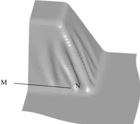
The simulation results show that wrinkling occurred in all three tapered square cups, and the simulated shape of the drawn cup for a die gap of 50 mm is shown in Fig. 4. It is seen in Fig. 4 that the wrinkling is distributed on the draw wall and is particularly obvious at the corner between adjacent walls. It is suggested that the wrinkling is due to the large unsupported area at the draw wall during the stamping process, also, the side length of the punch head and the die cavity
Fig. 4. Wrinkling in a tapered square cup (G⫽ 50 mm).
opening are different owing to the die gap. The sheet metal stretched between the punch head and the die cavity shoulder becomes unstable owing to the presence of compressive trans-verse stresses. The unconstrained stretching of the sheet metal under compression seems to be the main cause for the wrink-ling at the draw wall. In order to compare the results for the three different die gaps, the ratio of the two principal strains is introduced,  being ⑀min/⑀max, where ⑀max and ⑀min are the major and the minor principal strains, respectively. Hosford and Caddell [5] have shown that if the absolute value of  is greater than a critical value, wrinkling is supposed to occur, and the larger the absolute value of , the greater is the possibility of wrinkling.
The  values along the cross-section M–N at the same drawing height for the three simulated shapes with different die gaps, as marked in Fig. 4, are plotted in Fig. 5. It is noted from Fig. 5 that severe wrinkles are located close to the corner and fewer wrinkles occur in the middle of the draw wall for all three different die gaps. It is also noted that the bigger the die gap, the larger is the absolute value of . Consequently, increasing the die gap will increase the possibility of wrinkling occurring at the draw wall of the tapered square cup.
3.2 Effect of the Blank-Holder Force
It is well known that increasing the blank-holder force can help to eliminate wrinkling in the stamping process. In order to study the effectiveness of increased blank-holder force, the stamping of a tapered square cup with die gap of 50 mm, which is associated with severe wrinkling as stated above, was simulated with different values of blank-holder force. The blank-holder force was increased from 100 kN to 600 kN, which yielded a blank-holder pressure of 0.33 MPa and 1.98 MPa, respectively. The remaining simulation conditions are maintained the same as those specified in the previous section. An intermediate blank-holder force of 300 kN was also used in the simulation.
The simulation results show that an increase in the blank-holder force does not help to eliminate the wrinkling that occurs at the draw wall. The  values along the cross-section
M–N, as marked in Fig. 4, are compared with one another for
the stamping processes with blank-holder force of 100 kN and 600 kN. The simulation results indicate that the values along the cross-section M–N are almost identical in both cases. In order to examine the difference of the wrinkle shape for the two different blank-holder forces, five cross-sections of the draw wall at different heights from the bottom to the line M–
N, as marked in Fig. 4, are plotted in Fig. 6 for both cases.
It is noted from Fig. 6 that the waviness of the cross-sections for both cases is similar. This indicates that the blank-holder force does not affect the occurrence of wrinkling in the stamp-ing of a tapered square cup, because the formation of wrinkles is mainly due to the large unsupported area at the draw wall where large compressive transverse stresses exist. The blank-holder force has no influence on the instability mode of the material between the punch head and the die cavity shoulder.
4.
Stepped Rectangular Cup
In the stamping of a stepped rectangular cup, wrinkling occurs at the draw wall even though the die gaps are not so significant. Figure 1(b) shows a sketch of a punch shape used for stamping a stepped rectangular cup in which the draw wall C is followed by a step D–E. An actual production part that has this type of geometry was examined in the present study. The material used for this production part was 0.7 mm thick, and the stress– strain relation obtained from tensile tests is shown in Fig. 3.
The procedure in the press shop for the production of this stamping part consists of deep drawing followed by trimming. In the deep drawing process, no draw bead is employed on the die surface to facilitate the metal flow. However, owing to the small punch corner radius and complex geometry, a split occurred at the top edge of the punch and wrinkles were found to occur at the draw wall of the actual production part, as shown in Fig. 7. It is seen from Fig. 7 that wrinkles are distributed on the draw wall, but are more severe at the corner edges of the step, as marked by A–D and B–E in Fig. 1(b). The metal is torn apart along the whole top edge of the punch, as shown in Fig. 7, to form a split.
In order to provide a further understanding of the defor-mation of the sheet-blank during the stamping process, a finite-element analysis was conducted. The finite-finite-element simulation was first performed for the original design. The simulated shape of the part is shown from Fig. 8. It is noted from Fig. 8 that the mesh at the top edge of the part is stretched
Fig. 6. Cross-section lines at different heights of the draw wall for different blank-holder forces. (a) 100 kN. (b) 600 kN.
Fig. 7. Split and wrinkles in the production part.
Fig. 8. Simulated shape for the production part with split and wrinkles.
significantly, and that wrinkles are distributed at the draw wall, similar to those observed in the actual part.
The small punch radius, such as the radius along the edge
A–B, and the radius of the punch corner A, as marked in Fig.
1(b), are considered to be the major reasons for the wall breakage. However, according to the results of the finite-element analysis, splitting can be avoided by increasing the above-mentioned radii. This concept was validated by the actual production part manufactured with larger corner radii.
Several attempts were also made to eliminate the wrinkling. First, the blank-holder force was increased to twice the original value. However, just as for the results obtained in the previous section for the drawing of tapered square cup, the effect of blank-holder force on the elimination of wrinkling was not found to be significant. The same results are also obtained by increasing the friction or increasing the blank size. We conclude that this kind of wrinkling cannot be suppressed by increasing the stretching force.
Since wrinkles are formed because of excessive metal flow in certain regions, where the sheet is subjected to large com-pressive stresses, a straightforward method of eliminating the wrinkles is to add drawbars in the wrinkled area to absorb the redundant material. The drawbars should be added parallel to the direction of the wrinkles so that the redundant metal can be absorbed effectively. Based on this concept, two drawbars are added to the adjacent walls, as shown in Fig. 9, to absorb the excessive material. The simulation results show that the
Fig. 9. Drawbars added to the draw walls.
wrinkles at the corner of the step are absorbed by the drawbars as expected, however some wrinkles still appear at the remain-ing wall. This indicates the need to put more drawbars at the draw wall to absorb all the excess material. This is, however, not permissible from considerations of the part design.
One of the advantages of using finite-element analysis for the stamping process is that the deformed shape of the sheet blank can be monitored throughout the stamping process, which is not possible in the actual production process. A close look at the metal flow during the stamping process reveals that the sheet blank is first drawn into the die cavity by the punch head and the wrinkles are not formed until the sheet blank touches the step edge D–E marked in Fig. 1(b). The wrinkled shape is shown in Fig. 10. This provides valuable information for a possible modification of die design.
An initial surmise for the cause of the occurrence of wrink-ling is the uneven stretch of the sheet metal between the punch corner radius A and the step corner radius D, as indicated in Fig. 1(b). Therefore a modification of die design was carried out in which the step corner was cut off, as shown in Fig. 11, so that the stretch condition is changed favourably, which allows more stretch to be applied by increasing the step edges. However, wrinkles were still found at the draw wall of the cup. This result implies that wrinkles are introduced because of the uneven stretch between the whole punch head edge and the whole step edge, not merely between the punch corner and
Fig. 10. Wrinkle formed when the sheet blank touches the stepped edge.
Fig. 11. Cut-off of the stepped corner.
the step corner. In order to verify this idea, two modifications of the die design were suggested: one is to cut the whole step off, and the other is to add one more drawing operation, that is, to draw the desired shape using two drawing operations. The simulated shape for the former method is shown in Fig. 12. Since the lower step is cut off, the drawing process is quite similar to that of a rectangular cup drawing, as shown in Fig. 12. It is seen in Fig. 12 that the wrinkles were eliminated. In the two-operation drawing process, the sheet blank was first drawn to the deeper step, as shown in Fig. 13(a). Sub-sequently, the lower step was formed in the second drawing operation, and the desired shape was then obtained, as shown in Fig. 13(b). It is seen clearly in Fig. 13(b) that the stepped rectangular cup can be manufactured without wrinkling, by a two-operation drawing process. It should also be noted that in the two-operation drawing process, if an opposite sequence is applied, that is, the lower step is formed first and is followed by the drawing of the deeper step, the edge of the deeper step, as shown by A–B in Fig. 1(b), is prone to tearing because the metal cannot easily flow over the lower step into the die cavity. The finite-element simulations have indicated that the die design for stamping the desired stepped rectangular cup using one single draw operation is barely achieved. However, the manufacturing cost is expected to be much higher for the two-operation drawing process owing to the additional die cost and operation cost. In order to maintain a lower manufacturing cost, the part design engineer made suitable shape changes, and modified the die design according to the finite-element
Fig. 13. (a) First operation and (b) second operation in the two-operation drawing process. simulation result to cut off the lower step, as shown in Fig.
12. With the modified die design, the actual stamping die for production was manufactured and the production part was found to be free from wrinkles, as shown in Fig. 14. The part shape also agreed well with that obtained from the finite-element simulation.
In order to further validate the finite-element simulation results, the thickness distribution along the cross-section G–H obtained from the simulation result as indicated in Fig. 14,
Fig. 14. The defect-free production part.
was compared with those measured from the production part. The comparison is shown in Fig. 15. It can be seen in Fig. 15 that the predicted thickness distribution by finite-element simulation agrees well with that measured directly in the production part. This agreement confirms the effectiveness of the finite-element analysis.
5.
Summary and Concluding Remarks
Two types of wrinkling occurring in stamping processes were investigated using finite-element analysis, and the causes for wrinkling were examined and the methods to eliminate such wrinkles were developed.
The first type of wrinkling appears at the draw wall in the stamping of a tapered square cup. The occurrence of wrinkling is attributed to the large die gap, which is the difference between the side length of the die cavity opening and the side length of the punch head. The large die gap results in a large unsupported area of sheet metal when the metal is drawn into the die cavity and an unfavourable stretch between the punch head and die cavity shoulder. The large unsupported area of sheet metal is therefore prone to wrinkling. The finite-element simulations show that this type of wrinkling cannot be sup-pressed by increasing the blank-holder force.
Another type of wrinkling investigated occurs in an actual stamping part that has a stepped rectangular geometry. It is found that wrinkling occurs at the draw wall above the step even though the die gap is not sufficiently large. The wrinkling is due to the uneven stretch between the punch head and the step edge, according to the finite-element analysis. Several attempts were made in the die design to eliminate the wrinkling, using finite-element simulations, and an optimum design in which the step was cut off is finally established. The modified die design for eliminating wrinkles was validated by the pro-duction of a defect-free propro-duction part. The good agreement
between the simulation results and those observed in the drawn production part demonstrates the accuracy of the finite-element analysis, and the effectiveness of using finite-element simula-tions as a substitute for the expensive method of actual die try-outs is thereby confirmed.
Acknowledgements
The authors wish to thank the National Science Council of the Republic of China for the grant NSC-86–2212-E002–028 that made this project possible. They also wish to thank KYM for providing the production part.
References
1. K. Yoshida, H. Hayashi, K. Miyauchi, Y. Yamato, K. Abe, M. Usuda, R. Ishida and Y. Oike, “The effects of mechanical proper-ties of sheet metals on the growth and removing of buckles due to non-uniform stretching”, Scientific Papers, Institute of Physics and Chemistry Research, 68, pp. 85–93, 1974.
2. T. X. Yu, W. Johnson and W. J. Stronge, “Stamping and spring-back of circular plates deformed in hemispherical dies”,
Inter-national Journal of Mechanical Sciences, 26, pp. 131–148, 1984.
3. W. J. Stronge, M. P. F. Sutcliffe and T. X. Yu, “Wrinkling of elasto-plastic circular plates during stamping”, Experimental Mechanics, pp. 345–353, 1986.
4. R. Narayanasamy and R. Sowerby, “Wrinkling of sheet metals when drawing through a conical die”, Journal of Material Pro-cessing Technology, 41, pp. 275–290, 1994.
5. W. F. Hosford and R. M. Caddell, Metal Forming: Mechanics and Metallurgy, 2nd edn, 1993.