Analysis and Detection of Process Interaction Errors
Chin-Feng Fan and Shang-Lin Tsai
Computer Science and Engineering Dept., Yuan-Ze University, Taiwan
[email protected]
Abstract
- Among the new failure modes introduced by computer-controlled systems, process interaction error is the most unpredictable and serious one that may cause disastrous consequences. This paper proposes a fault tree approach to analyze such a failure mode, and a constraint-based approach to detect such failures at run time. The former provides a template focusing on interaction conflicts; the latter developed a range of interaction-oriented constraints for checking. Insights dealing with process interaction errors are also presented.Keywords: Fault trees analysis, process
interaction errors, mode confusion, constraints.
1. Introduction
Computer has been increasingly incorporated into safety-critical domains, such as aviation, transportation, nuclear, and medicine. Accidents occur during operating systems in these domains may result in disasters. New failure modes have been introduced by the incorporation of computer into such systems. Among the new failure modes, “process interaction error” is the most serious one. Here we use “process” to refer to the processes executed by computer software, hardware systems, as well as human operators. Traditional safety analysis focuses on equipment failure. However, current accidents of digital systems involve problems of interaction among equipment, computer, and humans. Interaction errors can be defined as unexpected situations during interaction between human-machine or hardware/software processes.
This paper presents a new fault tree method focusing on process interaction errors. It considers intention errors with conflicting pre-/post- conditions among processes. This approach makes the fault tree analysis systematic, repeatable, and visible. We have applied this fault tree template to successfully analyzing several past accidents. It can also be used in before-hand analysis. However, interaction error is an undecidable problem [1]; thus, analysis in advance cannot be complete. Run-time constraints should
also be used to monitor process interaction and detect possible problems in time so as to prevent potential accidents. A set of interaction-oriented constraints is presented in the paper. Among them, temporal and relational constraints are widely useful and effective. They can be used to check expected system states, responses, and human operations. Some empirical metrics of constraints are also addressed. With the proposed analysis and detection, the number of potential interaction errors can be effectively reduced.
2. Background
Fault tree analysis is a safety analysis technique widely used in nuclear, aerospace, and electronics industries. It uses a backward approach to analyze the causes of hazards. It uses AND/OR gates to describe the combination of causes for an undesired top event. Hardware fault trees terminate at the component failure events. Software fault tree (SFT) analysis [4] consists of a set of templates for different language constructs such as statement parts as failure causes. None of current fault tree methods focusing on interaction problems.
Mode confusion refers to the state when the operator has confused concepts of the current system working modes. It plays a major part in process interaction errors. Leveson [3] has classified mode confusion into the following six categories: interface interpretation error, inconsistent behavior, indirect mode changes, unintended side effects, lack of appropriate feedback, and operator authority limits.
Fault injection refers to the technique to introduce faults on purpose to test the system’s behavior so that its survivability or robustness can be observed. Fault injection was used in this research to check the effect of the presented constraints.
Constraints play a major role in Leveson’s new safety model STAMP [4]. SpecTRM-RL [7] is Leveson’s specification language with a set of constraints around 60 constraints with double counting. Most of them belong to variable level constraints dealing with input, output, or command.
This research extended SpecTRM-RL approach with more relational level and interaction oriented constraints.
3. Analysis Approach
3.1. Analysis model and error classification
From studying past interaction accidents, we then propose the following interaction error classification:
1. input errors 2. display errors 3. message errors 4. timing errors
5. shared resource errors
6. conflicting actions due to mode confusion Note that these categories are not independent. Timing errors may occur in the cases of input, display, or message errors; while, mode confusion usually happens due to display errors. Fig. 1 shows interaction in a computer controlled system with the above error types labeled with numbers in the figure to provide visual interpretation.
6.Mode confusion Computer Software Physical system Human process process resource message sensors actuators display input display message input input / command 1. 2. 5 3 3 1 1 2
Fig. 1. Process interaction model
3.2. Proposed fault tree approach
Most contemporary fault trees are constructed subjectively and do not focus on process interaction errors. We propose a fault tree template focusing on interaction errors, as shown in Fig. 2. We consider action errors and intention
errors are two major reasons of interaction errors.
The above error categories are considered as the root causes of the node “action errors”; they are message errors, input errors, display errors, and shared resources errors. Timing errors will be considered underneath them. In this paper, intention errors mainly consider mode confusion. In such cases, there must exist assumptions/conditions conflicts between related processes. Thus, under the node “intention errors”, conflicting pre- post-conditions between processes are identified as the basic reasons. Use of this fault tree template requires the following steps:
1. Draw state diagrams of each process with pre- and post-conditions for each state.
2. Identify the involved processes and their related states for the examined fault tree top event.
3. Find their conflicting pre- and post- conditions.
The advantage of this fault tree approach is that it is systematic, repeatable and transparent.
3.3. Case study
To demonstrate the use of the fault tree template, the Nagoya accident [7] was used as a case study. On April 26, 1994, a China Airline aircraft crashed at Nagoya Airport just before landing. The cause of this accident was due to the competing actions in landing between the pilot and the autopilot system. The fact that the autopilot was set was unaware of by the pilots. The state diagrams of the pilot and the autopilot are shown in Fig. 3. Note that the precondition of pilot’s manual mode is that “related system (object=autopilot; status= ┐control the plane)”; on the other hand, the post-condition of autopilot’s auto mode is that “object=autopilot; status=control the plane)”. When the pilot is at the manual mode and the autopilot is at the auto mode, a conflict occurs. A similar situation occurs when both the pilot and autopilot are idle. These two situations are shown in Fig. 7. The former situation led to Nagoya accident. This kind of conflicts due to intention errors can be identified algorithmically by checking preconditions and post-conditions among interactive/related processes to find conflicting pairs. Thus, by paring conflicting pre- and post-conditions, some irrational and unlikely interaction scenarios can even be identified in advance. Top event Interaction Error Input errors Display errors Conflict of P1’s post-condition & P2’s precondition (sequential) Conflict of P1’s precondition & P2’s precondition (concurrent) Message errors Shared resource errors
Action errors Intention errors
Conflict of P1’s post-condition & P2’s post-condition (concurrent) Other Hardware Error Process P1, P2
Idle [Auto On] [Auto Off] Precondition:… Post-condition: (object= autopilot; status =control the plane) Precondition:…
Post-condition: (object=autopilot, status = ┐control the plane)
Go Around [go Around] Auto State select [landing] Landing ….. autopilot Precondition : related subsystem ( object= autopilot, status= control the plane) Precondition:
related subsystem ( object= autopilot, status = ┐ control the plane) Post-condition…
pilot
Manual Idle
[Auto On]
[Auto Off]
Select Modes [done]
Fig. 3 Nagoya state diagrams
Action Error
Autopilot, state=Idle Ppostcondition (object=autopilot,
Status= ┐ control the plane)
Plane crash
Interaction Error
Conflict of A’s post condition & B’s pre condition
Intention errors
Pilot, state=Idle Pre -condtion: related system
(object=autopilot, status=control the plane )
Pilot, state=Manual Pre-condition: related system
(object=autopilot, status=┐control the plane ) Autopilot, state=Auto
Post-condition (object=autopilot, Status= control the plane)
….
A & B
…
Fig. 4. Nagoya accident fault tree
4.
Detection Approach
4.1. Proposed constraints
The above fault tree approach can successfully explain causes of interaction errors in past accidents; moreover, it can be used for analysis before hand. However, it is impossible to identify all kinds of potential interaction problems in
advance. Then, run-time monitoring using constraints can be used. It is an effective approach to dynamically detect possible interaction errors. Moreover, the pre- and post- conditions used in the above fault tree template can be viewed as constraints as well.
We extend SpecTRM-RL constraints and propose the following four levels of constraints. SpecTRM-RL constraints contain mainly the first two levels of constraints.
1. Variable level constraints:
They are local level constraints concerning a single variable. They include variable types, values, ranges checking, as well as hazardous values, and ranges checking. Data variations between two consecutive inputs/outputs are also considered. 2. Temporal constraints:
Since timing is important for interaction problems, temporal constraints are grouped into a distinct category. Temporal checking includes expected duration, age, and minimum/maximum time between two inputs/updates/messages.
3. Relational constraints:
They are constraints dealing with multiple variables and relations among these variables. Such constraints include relations among data, process variables, device states, and expected responses in normal system operation. Examples of process variables include temperature, pressure, water level, etc. for a control system. Conflict actions controlling the same device are also checked. Dependencies among process variables and devices can be expressed in constraints so that expected system behavior can be checked. Moreover, expected operational behavior should also be expressed by relational constraints for run time checking.
4. Global constraints:
They are constraints independent of process/device states. Global constraints may include conservation rules such as energy conservation and mass conservation, which should always hold for software variables which are images of states/variable in the physical world, in a computer-controlled system. Global constraints also include pragmatic concerns such as limitations, requirement, or set points for size, power, thresholds, etc.
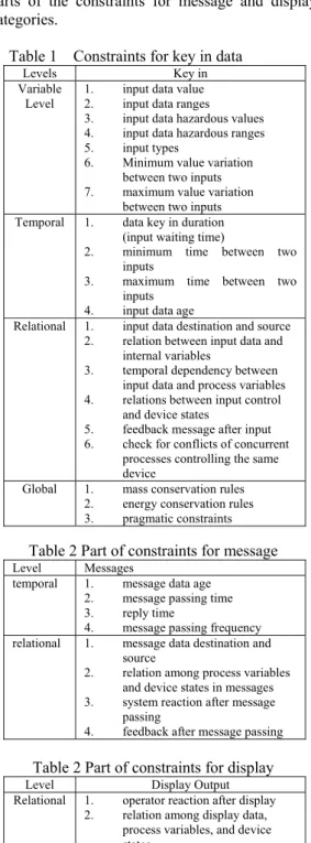
Based on our error types, these constraints are further categorized into key-in, display, message, and shared resources related constraints. Mode confusion errors can be detected by global or relational constraints. As an example, the constraints for key in data are given in Table 1. Constraints at the variable level and global level are pretty similar. Thus, Table 2 and 3 only show
parts of the constraints for message and display categories.
Table 1 Constraints for key in data
Levels Key in
Variable
Level 1. 2. input data value input data ranges 3. input data hazardous values 4. input data hazardous ranges 5. input types
6. Minimum value variation between two inputs 7. maximum value variation
between two inputs Temporal 1. data key in duration
(input waiting time)
2. minimum time between two inputs
3. maximum time between two inputs
4. input data age
Relational 1. input data destination and source 2. relation between input data and
internal variables
3. temporal dependency between input data and process variables 4. relations between input control
and device states
5. feedback message after input 6. check for conflicts of concurrent
processes controlling the same device
Global 1. mass conservation rules 2. energy conservation rules 3. pragmatic constraints
Table 2 Part of constraints for message
Level Messages temporal 1. message data age
2. message passing time 3. reply time
4. message passing frequency relational 1. message data destination and
source
2. relation among process variables and device states in messages 3. system reaction after message
passing
4. feedback after message passing
Table 2 Part of constraints for display
Level Display Output
Relational 1. operator reaction after display 2. relation among display data,
process variables, and device states
The proposed constraints focus on process interactions. Thus, expected states, expected operations, and responses can be checked using these constraints to detect potential interaction problems. For example, for global mass conservation rule, we may have the following constraint checking:
if(PUMP_state == OPEN)
if(WATER_Level_NOW !=
WATER_Level_beofre+Time_interval*Throughput) Warning();
The expected operation can also be checked according to operation rules:
If (State == INITIALIZATION) if(VALVE_STATE != OPEN ||
STEAM_BOILER_STATE != TURN_OFF || PUMP_STATE != OFF)
Warning();
4.2. Fault injection testing
To verify the effectiveness of these constraints, fault injections using two test cases (a steam boiler simulator and a simple air traffic controller [8]) have been performed. The steam boiler case considers a steam boiler with water pump and release valve as well as water level sensor. The air traffic controller will schedule planes’ take off and landing; the controller will key in such information as direction, velocity, and height for planes to follow
.
For example, the following two tests have been performed to test how constraints can solve mode confusion situation. Case 1 tested lack of feedback errors. The original scenario without constraint checking is as follows:
1) The system is at normal operation with an open pump.
2) An error occurs, and the system stop updating display; while the current water level is high. 3) The operator is unaware of the high water level. 4) Water level exceeds the safe level, which leads
to an emergency stop
The constraint that can be used to prevent such an incident is the “reply time limit” check:
Display(iWaterLevel); While(!GetInput()) {
ReplyWaitingTimer(5); }
Case 2 injected interface interpretation errors. The original scenario may be like:
1) The operator at the control center was supposed to key in direction, velocity, and height; but he mistakenly keyed in direction, height, and velocity.
2) The plane interpreted them as height , velocity as velocity and height. 3) The plane lost control and crashed. The potential useful constraint will be “input data hazardous ranges”:
If (INPUT_HEIGHT in HAZARDOUS_HEIGHT_RANGES)
Warning();
These experiments show that injected mode confusion errors can be successfully detected by proposed constraints. Our experience yields such
Display Error
Value Error Value RangeError HazardousValue Is Min Data In/Decrement Error Max Data In/Decrement Error Value Computation Relation Error Timing Error Conflict Of Conservation Rules Violate Duration Of Complete Display Violate Min Time Between Updates Violate Max Time Between Updates Violate Reply Time Limit After Display Fig. 5 Constraints as basic events
Blackout
Interaction Error
Action errors Intention errors
Display errors
(Stopped info-update) violate max time between updates
…
…….
Fig. 6 814 blackout fault tree conclusions as:
1. Multiple constraints may be needed for more complicated cases
2. Temporal constraints are widely useful since feedback checking in real time systems is critical.
3. Relational constraints are important to check expected operation and responses.
4. Resilient design is highly desirable.
5. Combining Constraints and the Fault
Tree
The proposed constraints can also be combined with previous fault tree template (Fig. 2) as the bottom basic event for the “action error” branch. Thus, the proposed analysis can consider constraint-level details. Fig. 5 shows the expansion of display error node with relevant constraint violation. This combination makes the
consideration of constraint violation be done before hand or after accidents occur. Fig. 6 is the fraction of the fault tree using the combined approach for the North America August 14, 2003 blackout [9]. The root cause was that the monitor could not be updated to indicate equipment failure; while this display fault was triggered by a previous race problem causing the EMS system in a deadlock state. This case apparently violated the maximum time between update constraint, as shown in Fig. 6.
6. Constraint Metrics
The number of proposed constraints is large. Then constraints’ effectiveness and sufficiency are issues. To estimate the cost-effectiveness of the proposed constraints, such metrics like constraint priority, coverage, effectiveness and sufficiency are designed and explained below:
(1) Constraint Priority: the degree of importance among a set of constraints.
This can be done by using the combined fault tree approach stated in Section 5. The priority can be determined by counting the number of occurrences of the examined constraint in the leaves of concerned major fault trees. Details may refer to a similar approach in our previous work dealing with general constraints [2].
(2) Constraint Coverage: the portion of instructions covered by a specific constraint.
For a constraint i, checked at the point of interest P, its coverage includes those instructions affecting the values of variables in i at P and those are affected by variables in i. The former can be computed using program slicing technique [10]. The latter refer to the use of these variables after P and before they are first updated. For example, constraint i is a relation of variables X, Y, and Z; i.e., i =R(X, Y, Z). Its coverage include the
program slices for X, Y, Z at point P; the number of these instructions is represented as Ib . The number of instructions using X, Y, Z after P and before these variables are updated is called If. Then,
Coverage i = (If + Ib) / Iall
where Iall is the number of all instructions. The wider the coverage of a constraint is, the more powerful it will be.
(3) Constraint Effectiveness: the probability to detect potential interaction errors.
We use fault injection experiments to calculate this metrics for constraint i. It is defined as
Effectiveness i = Di / F
Di is the number of detected faults F is the number of injected faults
(4) Constraint Sufficiency: the adequacy of a given set of constraints to detect the potential accidents or faults.
Results from fault tree analyses or fault injection tests can be used for calculation. Assuming N hazardous top events or N injected faults. The sufficiency of the set of constraints C refers to the ratio of these top events or injected faults that can be detected by C.
Sufficiency(N, C) = Fd / N
where Fd is the number of detected top events or faults
The last three metrics have values between 0 to 1; while value 1 is the best case.
These metrics provide quantitative information. But at the current stage, they are descriptive based on experiments. More prescriptive metrics should be developed in the future.
7. Conclusion
Human-computer interaction has been proven to be undecidable [1] In spite the undecidability, we should still make an effort to reduce potential interaction errors in advance, and to detect interaction errors in time once they occur. For preventive approach, designs should reduce interactive complexity and subsystem coupling; the analysis using the proposed template focusing on interaction errors may also work. For the detection approach, run-time monitoring using constraints is a promising approach. If we add sufficient and effective safety constraints to limit and check process interaction, this undecidable problem may then be monitored and controlled. Thus, it is a critical issue worth further investigation to design and determine the effective
and sufficient constraints.
Acknowledgement
This work was supported in part by National Science Council grant no. NSC 96-2221-E-155-047.
References
[1] P. Bottoni, S. Levialdi, and G. Paun (1998), “Successful Visual Human-computer Interaction is Undecidable,” Information
Processing Letter, 67 (1), pp. 13-19.
[2] C. F. Fan and C. Chen, “Constraint-based Software Specifications and Verification Using UML,” IEICE Trans. Information & System, Vol. E89-D, No. 6, June, 2006, pp. 1914-1922.
[3] N. G. Leveson, Safeware, Addison-Wesley, 1995.
[4] N. G. Leveson, “Systems-Theoretic Approach to Safety in Software-Intensive Systems,” IEEE Trans. on Dependable and Secure Computing, January 2005.
[5] N. G. Leveson et al. “Analyzing Software Specifications for Mode Confusion Potential,” Proceedings of the Workshop on Human Error and System Development, Glascow, March 1997.
[6] H. Sogame and P. Ladkin, “Aircraft accident investigation report 96-5: China airlines, Airbus Industrie A300B4-622R, B1816, Nagoya Airport, April 26, 1994,”
http://sunnyday.mit.edu/accidents/nag-content s.html.
[7] Software Engineering Corporation, “SpecTRM user manual,” www.software-eng.com. [8] S. Tsai, “Constraint-based Approach to Process
Interaction Errors,” Master’s thesis, Computer Engineering and Science Dept., Yuan-Ze. U., July, 2008. (in Chinese)
[9] U.S.-Canada Power System Outage Task Force, “Final report on the August 14, 2003 blackout in the United States and Canada: causes and recommendations,” April 2004.
[10] M. Weiser, “Program slicing". Proceedings of
the 5th International Conference on Software Engineering, pages 439–449, IEEE Computer