ESSP: An Embedded Software Synthesis and Prototyping Methodology
20
0
0
全文
(2) methodology.. Keywords Emulation Platform, Embedded Software, Software Synthesis, Prototyping, Quasi-Static Scheduling.. 1. INTRODUCTION Embedded systems have made a man’s life more convenient through easier controls and flexible configurations on many of our home amenities and office equipments. Due to the growing demand for more and more functionalities in embedded systems, an all-hardware implementation is no longer feasible because it is not only costly, but also not easily maintainable or upgradeable. Thus, software has gradually taken over a large portion of an embedded system’s functionalities. But, along with this flexibility, embedded software has also become highly complex. The past approach of starting everything from scratch is no longer viable. We need to use tools that automate several tedious tasks, but though there are some tools available for the design of embedded software, yet there is still a lack for a general design methodology. In this work, we are proposing a complete methodology, covering issues such as software synthesis, software verification, code generation, and system emulation. An embedded system is one that is installed in a large system with a dedicated functionality. Some examples include avionics flight control, vehicle cruise control, and network-enabled devices in home appliances. In general, embedded systems have a microprocessor for executing software and some hardware in the form of ASICs, DSP, and I/O peripherals. The hardware and software work together to accomplish some given function for a larger system. Embedded software are often hardware-dependent, thus it must be co-developed along with the development of the hardware, or the interface must be clearly defined. To satisfy all user-given constraints, formal approaches are a well-accepted design paradigm for embedded software [1], [2], [3], [4], [6]. Software synthesis is a process in which a formally modeled system can be synthesized by a. 2.
(3) scheduling algorithm into a set of feasible schedules that satisfy all user-given constraints on system functions and memory space. Due to its high expressiveness, Petri nets are a widely-used model. We propose and use a high-level variant of the model called Complex-Choice Petri Nets (CCPN). CCPN extends the previously used models called Free-Choice Petri Nets [12]. Thus, our synthesis algorithm also extends a previously proposed quasi-static scheduling algorithm. Details on the model and the proposed Extended Quasi-Static Scheduling (EQSS) algorithm along with code generation will be given in Section 3.2. Software verification formally analyzes the behavior of synthesized software to check if it satisfies all user-given constraints on function and memory space. In this verification process, we use the well-known model checking procedure to automatically verify synthesized software schedules. Further, we also need to estimate the amount of memory used by a generated software schedule. Details of this procedure will be given in Section 3.3. Finally, the generated embedded software is placed into an emulation platform for prototyping and debugging. The software code is downloaded into a single chip microcontroller. The hardware for software code emulation is programmed on an FPGA chip. According to the embedded software specifications, the settings of the input/output devices are configured. The embedded hardware and the I/O devices are then used for monitoring the functions of the embedded software through a debugger. The proposed ESSP methodology will be illustrated using two examples: a Vehicle Parking Management System (VPMS) [7] and a motor speed control system. Details are given in Section 4. This article is organized as follows. Section 2 gives a brief overview about previous work on embedded software synthesis, verification, and code generation. Section 3 describes the software synthesis method and our emulation platform architecture. Two embedded system examples are given in Section 4. Section 5 concludes the article and gives directions for future research work.. 3.
(4) 2. PREVIOUS WORK Several techniques for software synthesis from a concurrent functional specification have been proposed [5], [8], [9], [10], [11], [12], [15], [16]. Buck and Lee [8] have introduced the Boolean Data Flow (BDF) networks model and proposed an algorithm to compute a quasi-static schedule. However, the problem of scheduling BDF with bounded memory is undecidable, i.e. any algorithm may fail to find a schedule even if the BDF is schedulable. Hence, the algorithm proposed by Buck can find a solution only in special cases. Thoen et al. [9] proposed a technique to exploit static information in the specification and extract from a constraint graph description of the system statically schedulable clusters of threads. The limit of this approach is that it does not rely on a formal model and does not address the problem of checking whether a given specification is schedulable. Lin [10] proposed an algorithm that generates a software program from a concurrent process specification through an intermediate Petri-Nets representation. This approach is based on the strong assumption that the Petri Net is safe, i.e. buffers can store at most one data unit. This on one hand guarantees termination of the algorithm, on the other hand it makes impossible to handle multirate specifications, like FFT computations and down-sampling. Safeness implies that the model is always schedulable and therefore also Lin’s method does not address the problem of verifying schedulability of the specification. Moreover, safeness excludes the possibility to use Petri Nets where source and sink transitions model the interaction with the environment. This makes impossible to specify inputs with independent rate. Later, Zhu and Lin [11] proposed a compositional synthesis method that reduced the generated code size and thus was more efficient. Software synthesis method was proposed for a more general Petri-Net framework by Sgroi et al. [12]. A quasi-static scheduling algorithm was proposed for Free-Choice Petri Nets (FCPN) [12]. A necessary and sufficient condition was given for a FCPN to be schedulable. Schedulability was first tested for a FCPN and then a valid schedule generated. Decomposing a FCPN into a set of Conflict-Free (CF) components which were then individually and statically scheduled. Code was finally generated from the valid schedule. 4.
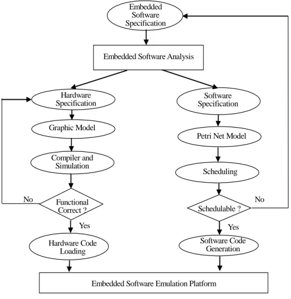
(5) Balarin et al. [2] proposed a software synthesis produce for reactive embedded systems in the Codesign Finite State Machine (CFSM) [13] framework with the POLIS hardware-software codesign tool [13]. This work cannot be easily extended to other more general frameworks. Recently, Su and Hsiung [15] proposed an Extended Quasi-Static Scheduling (EQSS) using Complex-Choice Petri Nets (CCPNs) as models to solve the issue of complex choice structures. Gau and Hsiung [16], [17] proposed a Time-Memory Scheduling (TMS) method for formally synthesizing and automatically generating code for real-time embedded software, using the Colored Time Petri Nets model. In our current work, we use EQSS to synthesize embedded software and use the code generation procedure from [15] to generate the C code for 8051 microcontroller. Several simulation or emulation boards for single chip micro-controller, such as Intel 8051 or ATMEL 89c51, have been developed. As we know, the platform for embedded software synthesis is still lacking. Therefore, we develop a flexible emulation environment for embedded software system. To the best of our knowledge, there are some emulation platforms available for embedded system design such as [18] [19]. In [18], a reconfigurable architecture platform for embedded control applications aimed at improving real time performance was proposed. In [19], the authors present the technology assessment of N2C platform of CoWare Inc., which proposes a solution to the co-design/co-simulation problem.. 3. EMBEDDED SOFTWARE SYNTHESIS AND PROTOTYPING METHODOLOGY In the automatic design of embedded software, there are several issues to be solved, including how software is to be synthesized and code generated, how software is to be verified, and how software code is to be emulated. Each of these issues was introduced in Section 1 and will be discussed at length in the rest of this Section. The overall flow of embedded software synthesis and the emulation of the generated software code on our prototype platform is as shown in Figure 1. Given an embedded software specification, we analyze it and then decide the requirements of the hardware within which the embedded 5.
(6) software is to be executed. The hardware is then synthesized by an FPGA/CPLD development tool and programmed into the chip of ALTERA or XILINX on our platform. On synthesis, if feasible software schedules cannot be generated then we rollback to the embedded software specification and ask the user to recheck or modify the specification. If feasible software schedules can be generated, then a C code for 8051 microcontroller will be generated by a code generation procedure. The machine executable code will be then generated using a 8051-specific C compiler. The target machine code is finally loaded into the 89C51 or 87C51 microcontroller chip on the platform.. Embedded Software Specification. Embedded Software Analysis. Hardware Specification. Software Specification. Graphic Model Petri Net Model Compiler and Simulation. No. Scheduling. No. Functional Correct ?. Schedulable ?. Yes. Yes Software Code Generation. Hardware Code Loading. Embedded Software Emulation Platform. Figure 1. Embedded Software Synthesis and Prototyping Methodology. 3.1 Software Synthesis and Code Generation Software synthesis is a scheduling process whereby feasible software schedules are generated, 6.
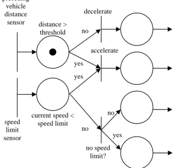
(7) which satisfy all user-given functional requirements, timing constraints, and memory constraints. Here, we proposed an Extended Quasi-Static Scheduling (EQSS) method for the synthesis of embedded software. EQSS takes a set of CCPN as input along with timing and memory constraints such as periods, deadlines, and an upper bound on system memory space. CCPN is defined as follows. Definition 1. Complex-Choice Petri Nets (CCPN) A Complex-Choice Petri Net is a 4-tuple (P, T, F, M0), where: z. P is a finite set of places,. z. T is a finite set of transitions, P ∪ T ≠ ∅, and P ∩ T = ∅,. z. F: (P × T) ∪ (T × P) → N is a weighted flow relation between places and transitions, represented by arcs, where N is the set of nonnegative integers. The flow relation has the following characteristics. . Synchronization at a transition is allowed between a branch arc of a choice place and another independent concurrent arc.. . Synchronization at a transition is not allowed between two or more branch arcs of the same choice place.. . A self-loop from a place back to itself is allowed only if there is an initial token in one of the places in the loop.. z. M0: P → N is the initial marking (assignment of tokens to places). Graphically, a CCPN can be depicted as shown in Fig. , where circles represent places, vertical. bars represent transitions, arrows represent arcs, black dots represent tokens, and integers labeled over arcs represent the weights as defined by F. Here, F(x, y) > 0 implies there is an arc from x to y with a weight of F(x, y), where x and y can be a place or a transition. Conflicts are allowed in a CCPN, where a conflict occurs when there is a token in a place with more than one outgoing arc such that only one enabled transition can fire, thus consuming the token and disabling all other transitions. The transitions are called conflicting and the place with the token is also called a choice. 7.
(8) place. For example, decelerate and accelerate are conflicting transitions in Fig. 2. Intuitions for the characteristics of the flow relation in a CCPN, as given in Definition 1, are as follows. First, unlike FCPN, confusions are also allowed in CCPN, where confusion is a result of synchronization between an arc of a choice place and another independently concurrent arc. For example, the accelerate transition in Fig. 2 is such a synchronization. Second, synchronization is not allowed between two or more arcs of the same choice place because arcs from a choice place represent (un)conditional branching, thus synchronizing them would amount to executing both branches, which conflicts with the original definition of a choice place (only one succeeding enabled transition is executed). Third, at least one place occurring in a loop of a CCPN should have an initial token because our EQSS scheduling method requires a CCPN to return to its initial marking after a finite complete cycle of markings. This is basically not a restriction as can be seen from most real-world system models because a loop without an initial token would result in either of two unrealistic situations: (1) loop triggered externally resulting in accumulation of infinite number of tokens in the loop, or (2) loop is never triggered. Through an analysis of the choice structures in a CCPN, EQSS generates a set of conflict-free components and then schedules each of them, if possible. Once each component can be scheduled to satisfy all constraints, the system is declared schedulable and code is generated in the C programming language. preceding vehicle distance sensor. decelerate distance > threshold. no accelerate yes yes. speed limit sensor. current speed < speed limit. no no yes no speed limit?. Figure 2 Automatic Cruise Controller CCPN Model 8.
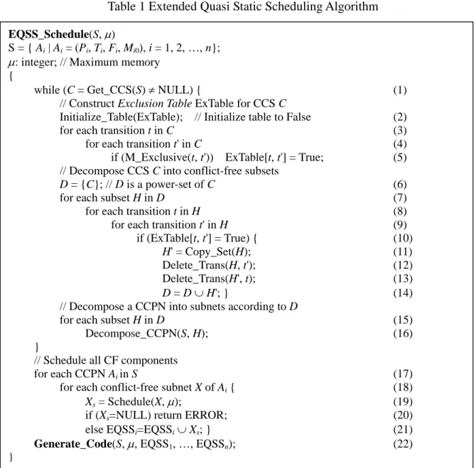
(9) Semantically, the behavior of a CCPN is given by a sequence of markings, where a marking is an assignment of tokens to places. Formally, a marking is a vector M = <m1, m2, …, m|P|>, where mi is the non-negative number of tokens in place pi ∈ P. Starting from an initial marking M0, a CCPN may transit to another marking through the firing of an enabled transition and re-assignment of tokens. A transition is said to be enabled when all its input places have the required number of tokens, where the required number of tokens is the weight as defined by the flow relation F. An enabled transition need not necessarily fire. But upon firing, the required number of tokens is removed from all the input places and the specified number of tokens is placed in the output places, where the specified number of tokens is that specified by the flow relation F on the connecting arcs. 3.1.1 Extended Quasi-Static Scheduling The details of our proposed EQSS algorithm are as shown in Table 1. Given a set of CCPNs S = { Ai | Ai = (Pi, Ti, Fi, Mi0), i = 1, 2, …, n} and a maximum bound on memory µ, the algorithm finds and processes each set of complex choice transitions (Step (1)), which is simply called Complex Choice Set (CCS) and is defined as follows. Definition 2. Complex Choice Set (CCS) Given a CCPN Ai = (Pi, Ti, Fi, Mi0), a subset of transitions C ⊆ Ti is called a complex choice set if they satisfy the following conditions. z. There exists a sequence of the transitions in C such that any two adjacent transitions are always conflicting transitions from the same choice place.. z. There is no other transition in Ti \ C that conflicts with any transition in C, which means C is maximal. From Definition 2, we can see that a free-choice is a special case of CCS. Thus, QSS also. becomes a part of EQSS. For each CCS, EQSS analyzes the mutual exclusiveness of the transitions in that CCS and then records their relations into an Exclusion Table (Steps (2)-(5)). Two complex-choice transitions are said to be mutually exclusive if the firing of any one of the two transitions disables the other transition. When the (i, j) element of an exclusion table is True, it 9.
(10) means the ith and the jth transitions are mutually exclusive, otherwise it is False. Based on the exclusion table, a CCS is decomposed into two or more conflict-free (CF) subsets, which are sets of transitions that do not have any conflicts, neither free-choice nor complex-choice. The decomposition is done as follows (Steps 6-14). For each pair of mutually exclusive transitions t, t', do as follows. z. Make a copy H' of the CCS H (Step (11)),. z. Delete t' from H (Step (12)), and. z. Delete t from H' (Step (13)). Table 1 Extended Quasi Static Scheduling Algorithm EQSS_Schedule(S, µ) S = { Ai | Ai = (Pi, Ti, Fi, Mi0), i = 1, 2, …, n}; µ: integer; // Maximum memory { while (C = Get_CCS(S) ≠ NULL) { // Construct Exclusion Table ExTable for CCS C Initialize_Table(ExTable); // Initialize table to False for each transition t in C for each transition t' in C if (M_Exclusive(t, t')) ExTable[t, t'] = True; // Decompose CCS C into conflict-free subsets D = {C}; // D is a power-set of C for each subset H in D for each transition t in H for each transition t' in H if (ExTable[t, t'] = True) { H' = Copy_Set(H); Delete_Trans(H, t'); Delete_Trans(H', t); D = D ∪ H'; } // Decompose a CCPN into subnets according to D for each subset H in D Decompose_CCPN(S, H); } // Schedule all CF components for each CCPN Ai in S for each conflict-free subnet X of Ai { Xs = Schedule(X, µ); if (Xs=NULL) return ERROR; else EQSSi=EQSSi ∪ Xs; } Generate_Code(S, µ, EQSS1, …, EQSSn); }. 10. (1) (2) (3) (4) (5) (6) (7) (8) (9) (10) (11) (12) (13) (14) (15) (16). (17) (18) (19) (20) (21) (22).
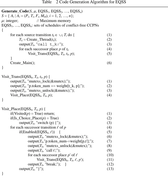
(11) Based on the CF subsets, a CCPN is decomposed into conflict-free components (subnets) (Steps (15)-(16)). The CF components are not distinct decompositions as a transition may occur in more than one component. Starting from an initial marking for each component, a finite complete cycle is constructed, where a finite complete cycle is a sequence of transition firings that returns the net to its initial marking. A CF component is said to be schedulable (Step (19)) if a finite complete cycle can be found for it and it is deadlock-free. Once all CF components of a CCPN are scheduled, a valid schedule for the CCPN can be generated as a set of the finite complete cycles. The reason why this set is a valid schedule is that since each component always returns to its initial marking, no tokens can get collected at any place. Satisfaction of memory bound is checked by observing if the memory space represented by the maximum number of tokens in any marking does not exceed the bound. Here, each token represents some amount of buffer space (i.e., memory) required after a computation (transition firing). Hence, the total amount of actual memory required is the memory space represented by the maximum number of tokens that can get collected at all the places in a marking during its transition from the initial marking back to its initial marking. Finally, embedded software code is generated (Step (22)), the details of which are given in Section 3.2.2. 3.1.2 Code Generation with Multiple Threads In contrast to the conventional single-threaded embedded software, we propose to generate embedded software with multiple threads, which can be processed for dispatch by a real-time operating system. Our rationalizations are as follows: (1) With advances in technology, the computing power of microprocessors in an embedded system has increased to a stage where fairly complex software can be executed. (2) Due to the great variety of user needs such as interactive interfacing, networking, and others, embedded software needs some level of concurrency and low context-switching overhead. (3) Multithreaded software architecture preserves the user-perceivable concurrencies among tasks, such that future maintenance becomes easier. The procedure for code generation with multiple threads (CGMT) is given in Table 2. Each 11.
(12) source transition in a CCPN represents an input event. Corresponding to each source transition, a P-thread is generated (Steps (1), (2)). Thus, the thread is activated whenever there is an incoming event represented by that source transition. There are two sub-procedures in the code generator, namely Visit_Trans() and Visit_Place(), which call each other in a recursive manner, thus visiting all transitions and places and generating the corresponding code segments. A CCPN transition represents a piece of user-given code, and is simply generated as call t_k; as in Step (3). Code generation begins by visiting the source transition, once for each of its successor places (Steps (4), (5)). Table. 2 Code Generation Algorithm for EQSS. Generate_Code(S, µ, EQSS1, EQSS2, …, EQSSn) S = { Ai | Ai = (Pi, Ti, Fi, Mi0), i = 1, 2, …, n}; µ: integer; // Maximum memory EQSS1, …, EQSSn: sets of schedules of conflict-free CCPNs { for each source transition tk ∈ ∪i Ti do { Tk = Create_Thread(tk); output(Tk, "call t_k;"); for each successor place p of tk Visit_Trans(EQSSk, Tk, tk, p); } Create_Main(); }. (1) (2) (3) (4) (5) (6). Visit_Trans(EQSSk, Tk, tk, p) { output(Tk, "mutexs_lock(&mutex);"); output(Tk, "p.token_num += weight[t_k, p];"); output(Tk, "mutexs_unlock(&mutex);"); Visit_Place(EQSSk, Tk, p); }. (1) (2) (3) (4). Visit_Place(EQSSk, Tk, p) { if(Visited(p) = True) return; if(Is_Choice_Place(p) = True) output(Tk, "switch (p) {"); for each successor transition t' of p if(Enabled(EQSSk, t')) { output(Tk, "mutexs_lock(&mutex);"); output(Tk,"p.token_num-=weight[p,t'];"); output(Tk, "mutexs_unlock(&mutex);"); output(Tk, "call t';"); for each successor place p' of t' Visit_Trans(EQSSk, Tk, t', p'); output(Tk, "break;"); } output(Tk, "}"); }. (1) (2) (3) (4) (5) (6) (7) (8) (9) (10) (11) (12) (13). 12.
(13) In both the sub-procedures Visit_Trans() (Steps (1)--(3)) and Visit_Place() (Steps (6-8)), a semaphore mutex is used for exclusive access to the token_num variable associated with a place. This semaphore is required because two or more concurrent threads may try to update the variable at the same time by producing or consuming tokens, which might result in inconsistencies. Based on the firing semantics of a CCPN, tokens are either consumed from an input place or produced into an output place, upon the firing of a transition. When visiting a choice place, a switch() construct is generated as in Step (3). 3.2 Embedded Software Verification There are three issues to be handled in software verification, that is: “what to verify”, “when to verify”, and “how to verify”? Each of these issues is solved as follows. In solution to the “what to verify” issue, CCPN models are translated into timed automata models which are then input to a model checker. Timed automata models are easier to verify than CCPN models because of its state space can be finitely represented. Since both CCPN and timed automata are formal models, there is an exact mapping between the two. For example, a marking of a CCPN is mapped to a state location of a timed automaton. Concurrency in CCPN is mapped to two or more concurrent timed automaton. Source transitions in CCPN are mapped to initial states of timed automata. Non-deterministic choice places in CCPN are mapped to states with branching transitions in timed automata. Loops in CCPN are mapped to loops in timed automata. In solution to the “when to verify” issue, we propose to verify software after scheduling (synthesis) and before code generation. Our rationalization is based on the fact that before scheduling or after code generation, the state-space is much larger than after scheduling and before code generation. A formal analysis proves this fact. Intuitively, before scheduling the state-space is much unconstrained than after scheduling, thus we have to explore a larger state-space if we verify before scheduling. Further, after code generation the state-space is also larger than that before code generation because upon code generation a lot of auxiliary and temporary variables are added, which add to the size of the state-space unnecessarily.. 13.
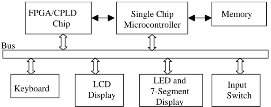
(14) In solution to the “how to verify” issue, we adopt a compositional model checking approach, where two timed automata are merged in each iteration and reduced using some state-space reduction techniques such as read-write reduction, symmetry reduction, clock shielding, and internal transition bypassing. The reduction techniques have all been implemented in the State Graph Manipulators (SGM) tool, which is a high-level model checker for real-time systems modeled as timed automata with properties specified in timed computation tree logic (TCTL). After the globally reduced state-graph is obtained, it is model checked for satisfaction of some user-given TCTL property. Details can be found in [20]. 3.3 Platform Architecture A platform supports a hardware-software environment for hardware emulation and software execution. In this work, we design a platform with an architecture as shown in Figure 2. The FPGA/CPLD chip is programmed according to the hardware requirements of an embedded system. The embedded software is downloaded into the microcontroller. If microcontroller memory is not enough, then external memory can be used. The input/output devices, such as keyboard, LCD display, LED display, and input switch are connected to FPGA/CPLD chip and microcontroller using a bus. The procedure adopted for emulating embedded software in a platform is as follows. (1) The embedded software code is downloaded into the ROM or Flash memory, (2) The settings of the I/O devices are configured according to the embedded software specifications, (3) The emulation platform is booted, input conditions are changed, and the output functions are checked for satisfaction of the functional requirements of the embedded software.. FPGA/CPLD Chip. Single Chip Microcontroller. Memory. Bus. Keyboard. LED and 7-Segment Display. LCD Display. Input Switch. Figure 3 Hardware-Software Prototype Platform Architecture. 14.
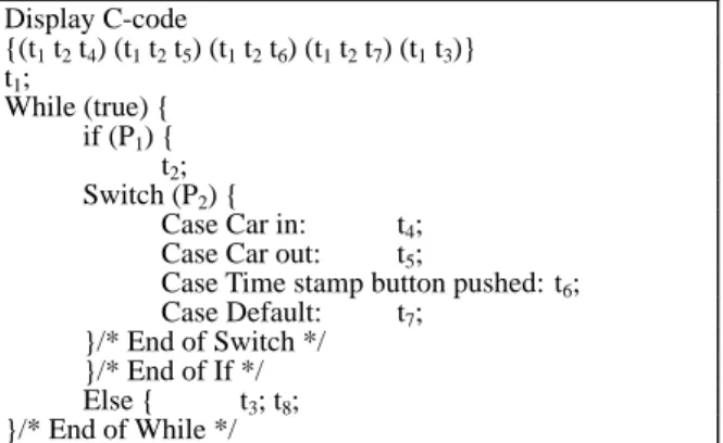
(15) 4. EMBEDDED SYSTEM EXAMPLES. In this section, we use two embedded system examples to illustrate our proposed embedded software synthesis and prototyping methodology. The first example is display subsystem of Vehicle Parking Management System (VPMS) example, which includes three subsystems: entry management system, exit management system, and display system. The display system consists of a control system (counter and display interface) and a 7-segment display device. The counter value (count) indicates the number of available parking vacancies. Further details on the VPMS specification can be found in [7]. The display system in VPMS was modeled as a CCPN as shown in Figure 3 and the CCPN transitions are given in Table 3. The embedded software code generated for the display system is shown in Figure 4, which was emulated using our ESSP platform. We use two input switches to simulate the Car in and Car out signals, respectively, and then use a 7-segment display to show the number of available parking vacancies. Table 3 CCPN Transitions in Display System. t4. Place P1. Description Counter value updated P2 Signal polling complete P3 Digit selected Transition Description t1 Initial counter t2 Poll signal t3 Select digit t4 Decrement counter t5 Increment counter t6 Check count t7 No operation t8 Display digit. t5 t2. t6 P2. t7. t1 P1. t3. t8 P3. Figure 4 Petri Net Model of Display System Display C-code {(t1 t2 t4) (t1 t2 t5) (t1 t2 t6) (t1 t2 t7) (t1 t3)} t1; While (true) { if (P1) { t2; Switch (P2) { Case Car in: t4; Case Car out: t5; Case Time stamp button pushed: t6; Case Default: t7; }/* End of Switch */ }/* End of If */ Else { t3; t8; }/* End of While */. Figure 5 Software Code for VPMS Display System 15.
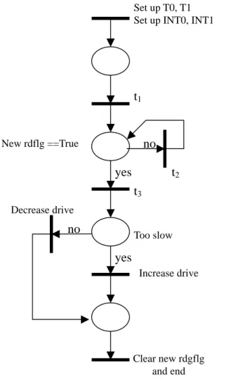
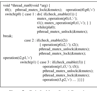
(16) Another example is a motor speed control system, whose CCPN model is as shown in Figure 6. The main function of this system is to adjust the speed of a motor based on its current speed. There are two timers T0, T1 and two interrupts INT0, INT1 that drive the system. On software synthesis, that is, EQSS, there are two feasible schedules for this system as given in Table 4, where an asterisk on a partial schedule indicates a loop of at least one iteration. The generated code is shown in Figure 7, which was emulated on our ESSP platform. We use two input switches to connect the trigger of INT0 and INT1, respectively. Motor speed is displayed by an LCD display device.. Set up T0, T1 Set up INT0, INT1. t1. no. New rdflg ==True. yes. t2 t3. Decrease drive. no. Too slow. yes Increase drive. Clear new rdgflg and end. Figure 6 Motor Control Speed System CCPN Model CCPN. #T. #P. #S. MSCS. 7. 4. 2. Schedules <t0, <t1>*, t2, t3, t6, t7, t8>, <t0, <t1>*, t2, t4, t5, t7, t8>. #T: #transitions, #P: #places, #S: #schedules. Table 4. Feasible Schedules for Motor System. 16.
(17) void *thread_run0(void *arg) { t0(); pthread_mutex_lock(&mutex); operation(t0,p0,'+') switch(p0) { case 1 : do{ if(check_enable(t1)) { mutex_operation(p0,t1,'-'); t1(); mutex_operation(p0,t1,'+'); } } while(pla0); pthread_mutex_unlock(&mutex); break; case 2 : if(check_enable(t2)) { operation(p0,t2,'-'); t2(); pthread_mutex_unlock(&mutex); pthread_mutex_lock(&mutex); operation(t2,p1,'+') switch(p1) { case 3 : if(check_enable(t3)) { operation(p1,t3,'-'); t3(); pthread_mutex_unlock(&mutex); pthread_mutex_lock(&mutex); operation(t3,p2,'+') … }}}}. Figure 7 Code for Motor Speed Control. 5. CONCLUSION AND FUTURE WORK. A complete methodology called ESSP was proposed for emulating hardware and synthesizing and executing embedded software, which includes an extended quasi-static scheduling algorithm, a code generation procedure, and an emulation platform. The methodology will not only reduce development time for embedded software, but also aid in debugging and testing its functional correctness. This version of our embedded software synthesis tool is still not very user-friendly. Therefore, we will improve it by adding a graphical user-interface in our next version.. 6. REFERENCES. [1]. K. Altisen, G. Gobler, A.Pneuli, J. Sifakis, S. Tripakis, and S. Yovine, “A framework for scheduler synthesis,” In Proceedings of the Real-Time System Symposium (RTSS’99), IEEE Computer Society Press, 1999.. [2]. F. Balarin and M. Chiodo. “Software synthesis for complex reactive embedded systems,” In. 17.
(18) Proceedings of International Conference on Computer Design (ICCD’99), IEEE CS Press,. October 1999, 634 – 639. [3]. L. A. Cortes, P. Eles, and Z. Peng, “Formal co-verification of embedded systems using model checking,” In Proceedings of EUROMICRO, 2000, 106 – 113.. [4]. P. -A. Hsiung, “Formal synthesis and code generation of embedded real-time software,” In International Symposium on Hard-ware/Software Codesign (CODES'01, Copenhagen,. Denmark), ACM Press, New York, USA, April 2001, 208 – 213. [5]. P.-A. Hsiung, “Formal Synthesis and Control of Soft Embedded Real-Time Systems," In Proc. 21st IFIP WG 6.1 International Conference on Formal Techniques for Networked and Distributed Systems (FORTE'01, Cheju Island, Korea), Kluwer Academic Publishers, August. 2001, 35 – 50. [6]. P. -A. Hsiung, W.-B. See, T.-Y. Lee, J.-M Fu, and S.-J. Chen, “Formal verification of embedded real-time software in component-based application frameworks,” In Proceedings of the 8th Asia-Pacific Software Engineering Conference (APSEC 2001, Macau, China),. IEEE CS Press, December 2001, 71 – 78. [7]. T.-Y. Lee, P.-A. Hsiung, and S.-J. Chen, “A case study in codesign of distributed systems — vehicle parking management system,” In Proceedings of the International Conference on Parallel and Distributed Processing Techniques and Applications (PDPTA'99, Las Vegas,. USA), CSREA Press, June 1999, 2982–2987. [8]. J. Buck, Scheduling dynamic dataflow graphs with bounded memory using the token flow model, Ph. D, dissertation, UC Berkeley, 1993.. [9]. F. Thoen et al, “Real-time multi-tasking in software synthesis for information processing systems,” In Proceeding of the International System Synthesis Symposium, 1995, 48 – 53.. [10] B. Lin, “Software synthesis of process-based concurrent programs,” IEEE/ACM 35th Design Automation Conference (DAC’98), June 1998, 502 – 505.. 18.
(19) [11] X. Zhu and B. Lin, “Compositional software synthesis of communicating processes,” IEEE International Conference on Computer Design, October 1999, 646 – 651.. [12] M. Sgroi and L. Lavagno, “Synthesis of embedded software using free-choice Petri nets,” IEEE/ACM 36th Design Automation Conference (DAC’99), June 1999, 805 – 810.. [13] F. Balarin et al., Hardware-software Co-design of Embedded Systems: the POLIS Approach, Kluwer Academic Publishers, 1997. [14] J. Zhu and R. Denton, “Timed Petri nets and their application to communication protocol specification,” In Proc. of the 21st IEEE Military Communication Conference, San Diego, CA, 1988, 195 – 199. [15] F.-S. Su and P.-A. Hsiung, “Extended quasi-static scheduling for formal synthesis and code generation of embedded software,” In Proc. of the 10th IEEE/ACM International Symposium on Hardware/Software Codesign, (CODES'2002, Colorado, USA), IEEE CS Press, May 2002,. 211 – 216. [16] C. -H. Gau and P. -A. Hsiung, “Time-memory scheduling and code generation of real-time embedded software,” In Proc. of the 8th International Conference on Real-Time Computing Systems and Applications (RTCSA'2002, Tokyo, Japan), March 2002, 19 – 27.. [17] P.-A. Hsiung and C.-H. Gau, “Formal Synthesis of Real-Time Embedded Software by Time-Memory Scheduling of Colored Time Petri Nets,” In Proc. of the Workshop on Theory and Practice of Timed Systems (TPTS'2002, Grenoble, France), Electronic Notes in Theoretical Computer Science (ENTCS), April 2002. [18] M. Baleani, F. Gennari, J. Yunjian, Y. Patel, R. K. Brayton, A. Sangiovanni-Vincentelli, “HW/SW partitioning and code generation of embedded control applications on a reconfigurable architecture platform,” In Proc. of the Tenth International Symposium on Hardware/Software Codesign (CODES’2002, Colorado, USA), IEEE CS Press, May 2002,. 151 – 156. [19] S. Tsasakou, N. S. Voros, M. Koziotis, D. Verkest, A. Prayati, and A. Birbas, 19.
(20) “Hardware-software co-design of embedded systems using CoWare’s N2C methodology for application development,” In Proc. of. the 6th IEEE International Conference on Electronics, Circuits and Systems (ICECS’1999, Pafos, Cyprus), IEEE CS Press, September 1999, Vol. 1,. 59 – 62. [20] F. Wang and P.-A. Hsiung, “Efficient and User-Friendly Verification,” IEEE Transactions on Computers, Vol. 51, No. 1, pp. 61-83, January 2002.. 20.
(21)
數據
+5
相關文件
Experiment code often includes messy scripts for various settings in the paper – useful for reviewers Software: for general users. One or a few reasonable settings with a
Managing and Evaluating an HCS siRNA Screen of the p53 Pathway with AcuityXpress Software.
3.16 Career-oriented studies provide courses alongside other school subjects and learning experiences in the senior secondary curriculum. They have been included in the
For the proposed algorithm, we establish a global convergence estimate in terms of the objective value, and moreover present a dual application to the standard SCLP, which leads to
The Hilbert space of an orbifold field theory [6] is decomposed into twisted sectors H g , that are labelled by the conjugacy classes [g] of the orbifold group, in our case
For the proposed algorithm, we establish its convergence properties, and also present a dual application to the SCLP, leading to an exponential multiplier method which is shown
Overview of a variety of business software, graphics and multimedia software, and home/personal/educational software Web applications and application software for
• Nokia has been using Socialtext wiki software for a year and a half to facilitate information exchange within its Insight &
