Intracavity measurement of liquid crystal layer
thickness by wavelength tuning of an external
cavity laser diode
Yu-Ping Lan, Yea-Feng Lin*, Yu-Tai Li and Ru-Pin Pan*
Department of Photonics and Institute of Electro-Optical Engineering, Department of Electrophysics* National Chiao Tung University
1001 Ta Hsueh Road, Hsinchu 30010, Taiwan, R.O.C. rpchao@mail.nctu.edu.tw
Chao-Kuei Lee
Institute of Electro-Optical Engineering and Semiconductor Technology Research and Development Center National Sun Yat-Sen University
70 Lien-hai Road, Kaohsiung 804, Taiwan, R.O.C chuckcklee@yahoo.com
Ci-Ling Pan
Department of Photonics and Institute of Electro-Optical Engineering National Chiao Tung University
1001 Ta Hsueh Road, Hsinchu 30010, Taiwan, R.O.C. clpan@faculty.nctu.edu.tw
Abstract: The gap of a planar-aligned liquid crystal (LC) cell is measured
by a novel method: Monitoring the change in output wavelength of an external-cavity diode laser by varying the voltage driving the LC cell placed in the laser cavity. This method is particularly suitable for measurement of LC cells of small phase retardation. Measurement errors of ±0.5 % and ±0.6 % for 9.6-μm and 4.25-μm cells with phase retardations of 1.63 μm and 0.20 μm respectively are demonstrated.
©2005 Optical Society of America
OCIS codes: (120.2040) Displays; (140.3410) Diode lasers; (140.3600) Lasers, tunable; (140.5960) Semiconductor lasers; (160.3710) Liquid crystal.
References
1. K. H. Yang, “Measurements of empty cell gap for liquid-crystal displays using interferometry methods,” J. Appl. Phys. 64, 4780-4781 (1988).
2. K. Y. Yang and H. Takano, “Measurements of twisted nematic cell gap by spectral and split-beam interferometric methods,” J. Appl. Phys. 67, 5-9 (1990).
3. Shyu-Mou Chen, Ru-Pin Pan, and Ci-Ling Pan, “Interferometric measurements of the thickness of nematic liquid crystal films with a free surface,” Appl. Opt. 28, 4969 – 4971 (1989).
4. A. Lien and H. Takano, “Cell gap measurement of filled twisted nematic liquid crystal displays by a phase compensation method,” J. Appl. Phys. 69, 1304-1309 (1991).
5. Hiap Liew Ong, “Cell thickness and surface pretilt angle measurements of a planar liquid-crystal cell with obliquely incident light,” J. Appl. Phys. 71, 140-144 (1992).
6. Seo Hern Lee, Won Sang Park, Gi-Dong Lee, Kwan-Young Han, Tae-Hoon Yoon, and Jae Chang Kim, “Low-cell-gap measurement by rotation of a wave retarder,” Jpn. J. Appl. Phys. 41, 379-383 (2002).
7. Marenori Kawamura, Yoshiaki Goto, and Susumu Sato, “Two-dimensional measurements of cell parameter distributions in reflective liquid crystal displays by using multiple wavelengths Stokes parameters,” J. Appl. Phys. 95, 4371-4375 (2004).
8. Zhan He, Ying Zhou, and Susumu, “A two-dimensional Stokes parameter method for determination of cell thickness and twist angle distributions in twisted nematic liquid crystal devices,” Jpn. J. Appl. Phys. 37, 1982-1988 (1998).
9. Jin Seog Gwag, Kyoung-Ho Park, Gi-Dong Lee, Tae-Hoon Yoon, and Jae Chang Kim, “Simple cell gap measurement method for twisted-nematic liquid crystal cells,” Jpn. J. Appl. Phys. 43, L30-L32 (2004). 10. Xinyu Zhu, Wing-Kit Choi, and Shin-Tson Wu, “A simple method for measuring the cell gap of a reflective
twisted nematic LCD,” IEEE Trans. Electron Dev. 49, 1863-1867 (2002).
11. Jong Seok Chae and Soo Gil Moon, “Cell parameter measurement of a twisted-nematic liquid crystal cell by the spectroscopic method,” J. Appl. Phys. 95, 3250-3254 (2004).
12. S. T. Tang and H. S. Kwok, “Transmissive liquid crystal cell parameters measurement by spectroscopic ellipsometry,” J. Appl. Phys. 89, 80-85 (2001)
13. Gi-Dong Lee, Tae-Hoon Yoon, and Jae Chang Kim, “Cell gap measurement method for single-polarizer reflective liquid crystal cells,” Jpn. J. Appl. Phys. 40, 3330-3331 (2001).
14. Yu-Ping Lan, Chao-Yuan Chen, Ru-Pin Pan, and Ci-Ling Pan, “Fine-tuning of a diode laser wavelength with a intracavity liquid crystal element,” Opt. Eng. 43, 234-238 (2004)
15. Yu-Ping Lan, Ru-Pin Pan and Ci-Ling Pan, “Mode-hop-free fine-tuning of an external cavity diode laser with an intracavity liquid crystal cell,” Opt. Lett. 29, 510-512 (2004).
16. Shin-Tson Wu, Chiung-Sheng Wu, Marc Warenghem, and Mimoun Ismaili, “Refractive index disperasions of liquid crystals,” Opt. Eng. 32, 1775-1780 (1993).
17. Ru-Pin Pan, Shyang-Rong Liou, and Chao-Ken Lin, “Voltage-controlled optical fiber coupler using a layer of low-refractive-index liquid crystal with positive dielectric anisotropy,” Jpn. J. Appl. Phys. 34, 6410-6415 (1995).
1. Introduction
The cell thickness or cell gap is one of the key parameters in the design and fabrication of liquid crystal displays (LCD). For example, it affects the brightness, contrast ratio and response speed of the LCDs. Traditionally, the cell gaps of an empty [1], or filled [2] LC cell, even LC film with a free surface [3] are measured using interferometric methods. To date, many methods of measuring the cell gap in a filled cell of either transmissive or reflective LCDs have been developed. These include methods based on phase compensation [4-7], Jones Matrix calculation with rotating polarizers [8-10], and spectroscopic [11-13] methods. All of the methods except the interferometric method employ the polarizer and analyzer pairs. The measurement accuracy thus depends on the precision of the rotation stages for the polarizer and analyzer as well as extinction of the pair. By far, the rotating polarizer method is the most popular one. Briefly, the optical transmittance of a LC cell placed between a polarizer and an analyzer is measured as a function of rotation angle. Analysis of the intensity of the transmitted light through the setup provides information on the cell thickness. Small cell gaps, however, can not be easily measured by the rotating polarizer method. To overcome these problems, the total intensity ratio method [9] have been proposed and demonstrated. Cell gap of a reflective twisted nematic LCD was successfully measured by taking the ratio of reflected light intensity at two different polarizer angles [10]. These authors report accuracies of 1~2 %. Measurements by the above two methods are free from multiple solutions for the LC layer thickness, but a suitable range of wavelengths should be chosen to achieve desired accuracy. Chao and Moon [11] proposed a method of determining the cell thickness by the transmission spectrum containing variation points at given polarizer and analyzer angles. The accuracy is primarily limited by the process of choosing a variation point and the error is a little higher than the rotating polarizer method.
In this paper, we propose a novel method of determining the thickness of a LC layer by measuring the change in laser wavelength induced by dΔn (d is the thickness and Δn is the
birefriengence) of the LC cell in the laser cavity. The concept is derived from our previously work on fine-tuning of an external-cavity laser diode (ECL) with an intra-cavity LC cell[14, 15]. The measurement errors are ~1 % for either thick or thin LC cells.
2. Operation principles
In a nematic LC material, which is uniaxially birefringent, the refractive index of the ordinary light is independent of the direction of light propagation. The extraordinary refractive index of the nematic LC given by Eq. (1), on the other hand, depends on the angle θ between the optic axis of the LC and the incident beam direction,
( )
sin2( )
cos2( )
−1/2 ⎥ ⎦ ⎤ ⎢ ⎣ ⎡ + = o e eff n n nθ
θ
θ
, (1) where no is the ordinary refractive index and ne is the extraordinary refractive index for θ =90°. Thus the LC cell can be viewed as a phase retarder. In general, if θ = θ(z), then neff (θ) =
neff(z). The phase retardation ΔΦ of light propagating through the LC layer is expressed as
( )
[
n z n]
dz k d eff 0 0∫
− = ΔΦ , (2) where k = 2π/λ, λ is the wavelength of the incident light, d is the thickness of the LC layer. The maximum phase retardation is given by(
ne no)
d2
max = −
ΔΦ
λπ . (3) Let us consider a planar-aligned LC cell inside the laser cavity and the laser polarization direction is along the easy direction, i.e., the direction along which the liquid crystal molecules are aligned. Varying the voltage driving the LC cell, its extraordinary index of refraction would change due to field-induced reorientation of the LC director (the thermal average orientation of the liquid crystal molecules) and bring about additional intra-cavity phase retardation ΔΦ. This corresponds to a change in laser cavity length by Δl=ΔΦ/k. The resulting shift of the laser output wavelength Δλ is then given by
l l
λ λ
Δ = − Δ , (4)
where l is the cavity length and λ is the output wavelength. By measuring Δλ, we can calculate the retardation from Eq. (4). Further, if the birefringence Δn = (ne-no) of the LC is
known, then the LC layer thickness d can be derived.
3. Experimental setup
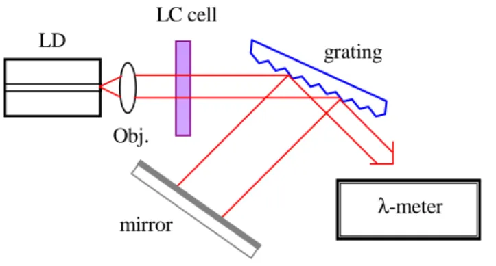
A schematic configuration for our LC layer thickness measurement setup is shown in Fig. 1.
Fig. 1. The schematic diagram for LC cell gap measurement. LD: laser diode; Obj: Objective, LC: liquid crystal, λ-meter: wavelength meter.
The gain-medium is a laser diode (LD, Sacher 830) with one facet anti-reflection (AR) coated to suppress self-lasing and the other facet coated as a high-reflector (HR). The temperature of the laser diode is stabilized at 20.0±0.01 °C. The output from the AR-coated facet of the LD is
LC cell LD
grating
mirror λ-meter
collimated by an objective lens (numerical aperture, N.A. = 0.5) for optical coupling to the diffraction grating (1200 lines/mm) at grazing-incidence. The zeroth-order reflected beam from the grating is the output of the laser. The first-order reflection from the grating is retroreflected back into the diode by an end mirror. The LC cell is introduced between the LD and the grating. The output wavelength of the ECL is measured by a high precision wavelength meter (λ-meter) with a resolution of 0.0001 nm (Burleigh WA-1500). The coefficient for current-tuning of the laser, β=Δλ/ΔI, is 4.7×10⁻³ nm/mA over a range of ΔI = ± 4 mA around a bias current of I = 52 mA. Continuous mode-hop-free tuning of laser wavelength is accomplished by simultaneously changing the voltage driving the LC cell and the bias current of the LD synchronously [15].
3. Results and discussions
As a first demonstration, we prepared two transmission-type planar-aligned nematic LC cells with different cell gaps and LC materials. The empty cells were first measured by using the interferometric method to be 9.6 um and 4.25 um [1]. The LC cells used in the experiment were driven by a square wave voltage waveform at 1 kHz and operated at the environmental temperature of 25±0.1 °C. 0 2 4 6 8 10 815.440 815.442 815.444 815.446 815.448 815.450 λ (n m ) Vrms (V) (a) 0 2 4 6 8 0.0 0.3 0.6 0.9 1.2 T ran s m it ta nc e ( m W ) Vrms (V) (b)
Fig. 2. (a) Output wavelength of the laser and (b) transmittance of the LC cell (9.6 μm) through crossed polarizers as a function of the driving root-mean square (rms) voltage of the LC cell.
One cell of 9.6 μm gap is filled with nematic LC 5CB (Merck) and inserted into the laser cavity. First of all, the cavity length is determined to be 16.62 cm at λ=815.4409 nm by tuning the wavelength while allowing the laser to mode hop. Next, the mode-hop-free tuning range of the laser as a function of the driving voltage of the LC cell is found to be 0.0080 nm (See Fig. 2 (a)). The synchronous change in LD current required for mode-hop-free tuning is 1.5 mA, which is in good agreement with theoretical prediction of 1.7 mA (ΔI=Δλ/β=0.008/4.7×10-3=1.7 mA). Thus the retardation due to the LC cell is 1.63 μm according to Eq. (4). By fitting the data published by S. –T. Wu et al. [16], we determine the birefringence of 5CB to be 0.169 at λ =815 nm at T=25.1 °C. The LC layer thickness d is thus calculated to be 9.65 μm. Independently, d is measured by the crossed-polarizer configuration [10]. In this method, the transmittance of the LC cell between crossed polarizers is measured as a function of its driving voltage. The probing laser wavelength is 814.8140 nm. The result is shown in Fig. 2(b). Each cycle in Fig. 2(b) corresponds to a phase retardation of 2π. Thus a
phase retardation of ΔΦ=3.73π is obtained by ramping the driving voltage from 0 V to 10 V. The optical path length of the LC layer is 1.52 μm, corresponding to a thickness of 8.99 μm.
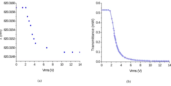
In the second experiment, an empty LC cell of 4.25 μm in thickness is filled with the nematic LC 18523 (BDH), which is a low-birefringence LC prepared by mixing highly fluorinated low-refractive-index organic compound additives in hydrocarbon LC hosts. As in the first example, the cavity length is first measured to be 16.62 cm at λ=820.3159 nm. The mode-hop-free tuning range of the laser as a function of the driving voltage of this LC cell is found to be 0.0010 nm (See Fig. 3(a)). The corresponding retardation is 0.20 μm. The birefringence of BDH-18523 is determined by interpolating the data from Merck at 0.636 μm and the data published by R. -P. Pan et al. at 1.3 and 1.5 μm [17]. The birefringence is thus estimated to be 0.04737 at λ=820 nm and T=25 °C. The LC layer thickness, d is then 4.28
μm. In this case, we can not measure d by using the simple crossed-polarizer configuration. As shown in Fig. 3(b), the transmittance curve is less than one cycle, i.e. the phase retardation
ΔΦ is less than 1π. 0 2 4 6 8 10 12 14 820.3148 820.3150 820.3152 820.3154 820.3156 820.3158 820.3160 λ (n m) Vrms (V) (a) 0 2 4 6 8 10 12 14 0.0 0.1 0.2 0.3 0.4 0.5 0.6 T ran s m it ta nc e ( m W ) Vrms (V) (b)
Fig. 3. (a) Output wavelength of the laser and (b) transmittance of the LC cell (4.25 μm) through crossed polarizers as a function of the driving root-mean-square (rms) voltage of the LC cell.
The LC layer thickness measured by the wavelength tuning method, the interferometric method and the crossed-polarizer method are summarized in Table 1.
Table 1. Results of LC layer thickness measurement
Interferometric
(empty cell) Wavelength tuning
Crossed-polarizers
d (μm) 9.6 9.7 (1.63) 9.0 (1.52)
d (μm) 4.25 4.2 (0.20)
The values listed in the parentheses are the retardations, dΔn (unit: μm). LC layer thickness measured by the present method are in good agreements with those measured by the interferometric method, i.e., 1.0 % and 1.2 % for the thick (9.6 μm) and thin (4.25 μm) cells, respectively. The accuracy of thickness measurements by the present method depends on the uncertainties in the cavity length, birefringence Δn, tilted angle of the LC cell with respect to
the propagation direction of the laser, drift of the laser frequency (wavelength), and the resolution of the wavelength meter. The error sources of the present method are broken down and discussed below:
3.1 Wavelength meter:δλ
The resolution of the wavelength meter is 0.0001 nm. The accuracy is assumed to be
±0.00005 nm. The relation between the error of thickness measurement δd and the accuracy
of the wavelength meter δ(Δλ) can be derived by differentiating Eq. (4):
( )
d d ⋅ Δ Δ ≈ λλ δ δ . (5) According to above equation, the measurement error is ±0.06 μm for the cell with d=9.6 μm. The wavelength tuning range of the ECL is Δλ=0.0080 nm, and ±0.21μm for the cell withd=4.25 μm with the corresponding wavelength tuning range of Δλ=0.0010 nm.
3.2 Drift of laser frequency (wavelength):δf (δλ)
During environmental perturbation, the frequency of the ECL in the free-running mode could drift by ~200 MHz during an hour. Thus |δλ|/λ = |δf|/f = 5.43×10⁻⁷ for λ = 815 nm (f = 368 THz). The relation between δd and the frequency drift of the free-running laser mode δf is
given by f f n d δ δ Δ = 1 . (6) According to Eq. (6), the corresponding measurement error is 0.534 μm for a cavity length of 16.62 cm and LC birefringence Δn = 0.169 (5CB). For a cell with a thin LC layer, e.g., d =
4.25 μm, the measurement time is short (less than 3 minutes). Thus the measurement error due to laser frequency drift is 0.095 μm for δf/f = 2.72×10⁻⁸ and LC birefringence Δn =
0.04737 (BDH18523).
3.3 Uncertainty in cavity length: δl
The relation between δd and the accuracy of the measurement of cavity length δl is given by l
d l
d δ
δ = . (7) If the cavity length is known with an accuracy of ± 0.1 mm, and the cavity length is 16.62 cm, the accuracy of the cell gap measurement is ±0.006 μm for the 9.6-μm cell and ±0.003 μm for the 4.25-μm cell.
3.4 Birefringence: δ(Δn)
The relation between δd and the accuracy of the birefringence δ(Δn) of the LC can be written as
( )
( )
n( )
n d n n d Δ Δ = Δ Δ Δ = δ δ λ λ δ 2 (8) The birefringence δ(Δn)/ΔT is -1.524×10⁻³ /°C for 5CB [16]. During the course of the experiment, the room temperature changes by the amount ±0.1 °C. The corresponding variation in birefringence Δn is then 1.524×10⁻⁴. The accuracy of the cell gap is thus 0.009 μmfor the 9.6-μm cell. The measurement error resulting from variation in Δn is negligible for the 4.25-μm cell.
3.5 Angle: δθ
Variation of the angle between the propagation direction of laser light in the ECL and normal of the LC cell θ will also induce measurement errors. The relation between θ, measured thickness dM and the true thickness d is dM = d/cosθ. The relations between δd and the accuracy of the angle δθ is then
δθ θ
δd =dtan ⋅ . (9) The corresponding error in cell gap d is 0.003 μm for a 9.6-μm cell and 0.001 μm for a
4.25-μm cell when the angle θ= 10° and δθ= 0.1° (6 min. of arc).
We summarize the error sources of the present method in Table 2.
Table 2. Error sources for LC layer thickness measurement by the present method
Errors (μm) Error sources Symbols Quantity
9.6 μm cell 4.25 μm cell Wavelength meter δλ 0.00005 nm 0.06 0.21 Drift of laser frequency δf 200 MHz 0.534 0.095
Cavity length δl 1 mm 0.006 0.003
Birefringence δ(Δn) 1.524×10⁻⁴ 0.009 ⎯
Angle δθ 0.1° 0.003 0.001
Combined error 0.537 0.23
Clearly, the accuracy of our cell gap measurement is limited mainly by the resolution of the wavelength meter and the frequency drift of the ECL. The frequency drift of our ECL is primarily caused by the thermal drift or mechanical instability of the laser cavity. Obviously, there is still a lot of room for improvement, e. g. constructing the ECL to be more rigid and reducing the effect of temperature variation in the laboratory by isolating the laser system in a box, even employing a temperature-compensating mechanism for the external cavity. Instead of the wavelength meter, the laser frequency can be measured by heterodyning the ECL with a frequency-stabilized laser. The beating signal between the two lasers can be easily detected with a typical resolution of 100 kHz, which is about five hundred times better than that of the wavelength meter. Employing both approaches, the phase retardation due to the LC layer as small as 4×10⁻⁵ μm can be measured. This is more than meeting the requirement for the manufacture of LCD panels at present.
The present method can also be applied to measure the cell gap of the vertical-aligned (VA) liquid crystal panels widely employed by the LCD industry for enlarging the viewing angle. The optical axis of the VA LC is in a direction perpendicular to the glass surfaces. Thus the type of variation in birefringence is similar to the planar-aligned LC cells reported here.
4. Conclusion
The gap of a planar-aligned liquid crystal (LC) cell is measured by a novel method: Monitoring the change in output wavelength of an external-cavity diode laser by varying the voltage driving the LC cell placed in the laser cavity. This method is particularly suitable for measurement of LC cells of small phase retardation. Measurement errors of ±0.5 % and ±0.6 % for 9.6-μm and 4.25-μm cells are demonstrated. This is more than sufficient for the
requirement of the LCD industry. The error sources of this method are analyzed and found to be dominated by the wavelength meter used for monitoring the laser wavelength and its drift during the course of the experiment. Both can be readily improved with known techniques. The proposed method is also suitable for measurement of vertical-aligned LC cells widely employed by the LCD industry for enlarging the viewing angle.
Acknowledgments
This work was supported in part by various grants from the National Science Council and Ministry of Education of the Republic of China. Yu-Ping Lan is also affiliated with Center for Measurement Standards of Taiwan R.O.C.