Index Rendering: Hardware-Efficient Architecture
for 3-D Graphics in Multimedia System
Bor-Sung Liang, Yuan-Chung Lee, Wen-Chang Yeh, and Chein-Wei Jen, Member, IEEE
Abstract—Real-time three-dimensional (3-D) graphics emerges rapidly in multimedia applications, but it suffers from require-ments for huge computation, high bandwidth, and large buffer. In order to achieve hardware efficiency for 3-D graphics rendering, we propose a novel approach named index rendering. The basic concept of index rendering is to realize 3-D rendering pipeline by using asynchronous multi-dataflows. Because triangle information can be divided into several parts with each part capable of being transferred independently and asynchronously. At last, all data are converged by the index to generate the final image.
Index rendering approach can eliminate unnecessary oper-ations in traditional 3-D graphics pipeline. The unnecessary operations are caused by the invisible pixels and triangles in the 3-D scene. Previous work, deferred shading, eliminates the operations relating to invisible pixels, but it requires huge trade-offs in bandwidth and buffer size. With index rendering, we can eliminate operations on both invisible pixels and triangles with less tradeoffs as compared with deferred shading approach.
The simulation and analysis results show that the index ren-dering approach can reduce 10%–70% of lighting operations when using flat and Gouraud shading process and decrease 30%–95% when using Phong shading. Furthermore, it saves 70% of buffer size and 50%–70% of bandwidth compared with deferred shading approach. The result also indicates that this approach of index ren-dering is especially suitable for low-cost portable renren-dering device. Hence, index rendering is a hardware-efficient architecture for 3-D graphics, and it makes rendering hardware easier to be integrated into multimedia system, especially in system-on-a-chip (SOC) de-sign.
Index Terms—Rendering, rendering architecture, 3-D graphics.
I. INTRODUCTION
T
HREE-DIMENSIONAL (3-D) graphics has emerged rapidly from technical areas to nontechnical areas, and it has also become a key module in multimedia systems. InManuscript received December 13, 1999; revised January 18, 2002. This work was supported by the National Science Council of Taiwan, R.O.C., under Grant NSC-89-2218-E009-085. The associate editor coordinating the review of this paper and approving it for publications was Dr. Francky Catthoor.
B.-S. Liang was with the Department of Electronics Engineering, National Chiao-Tung University, Hsinchu 300, Taiwan, R.O.C. He is now with Sunplus Technology, Hsinchu 300, Taiwan, R.O.C. (e-mail: bsliang@sunplus.com.tw).
Y.-C. Lee was with the Department of Electronics Engineering, National Chiao-Tung University, Hsinchu 300, Taiwan, R.O.C. He is now with MediaTek, Inc., Hsinchu 300, Taiwan, R.O.C. (e-mail: yzlee@ee.nctu.edu.tw). W.-C. Yeh was with the Department of Electronics Engineering, National Chiao-Tung University, Hsinchu 300, Taiwan, R.O.C. He is now with ZyDAS Corporation, Hsinchu 300, Taiwan, R.O.C. (e-mail: wcyeh@twins.ee.nctu.edu.tw).
C.-W. Jen is with the Department of Electronics Engineering, Na-tional Chiao-Tung University, Hsinchu 300, Taiwan, R.O.C. (e-mail: cwjen@twins.ee.nctu.edu.tw).
Digital Object Identifier 10.1109/TMM.2002.802008.
fact, real-time 3-D graphics is expanding in high gear as a core technology in the areas of user interface, virtual reality, visualization, and entertainment. However, real-time 3-D graphics rendering is computation-intensive, which requires high bandwidth and large buffer memory. Recently, many systems [1]–[6] have proposed for various applications of real-time 3-D graphics, and most of them are performance-ori-ented architectures that require high hardware cost.
In order to realize real-time 3-D graphics in commodity hard-ware, one way to proceed is to make an attenuated version of tra-ditional architecture, but it degrades the performance and image quality. An alternative method is to design a new rendering ar-chitecture, such as Talisman [7], [8]. This architecture employs techniques from two-dimensional (2-D) image processing and changes into 3-D image synthesis, but it is not compatible with traditional rendering architecture. Therefore, all air position in-dicators (APIs) and programs should be rewritten to fit into this architecture. A better approach is to design a new hardware-effi-cient architecture compatible with a traditional architecture. De-ferred shading is one of the kinds of architecture. It rearranges the operations in traditional rendering pipeline to eliminate re-dundant operations on invisible pixels. However, it suffers from large internal bandwidth and buffers, which is hard to be imple-mented in commodity system.
Furthermore, hardware efficiency is another important issue. Generally speaking, 3-D applications on PCs are performance-oriented, and the advancement of rendering hardware is driven by brute-forced VLSI technology. However, it limits the 3-D ap-plications on low-cost portable devices. In low-cost portable de-vices, most functions are application-oriented. Hence, the high performance is not the only issue, and the importance of hard-ware efficiency emerges. This is because low hardhard-ware effi-ciency not only wastes hardware resource but it also leads to power problems.
Hence, in this paper we propose a new approach, index rendering, for hardware-effective 3-D graphics rendering. It can further eliminate unnecessary operations on both invisible pixels and hidden triangles and avoid huge tradeoffs of de-ferred shading. The organization of this paper is described as following: In Section II, we first review 3-D graphics rendering pipeline. By observing the traditional rendering pipeline, we can find that data rate dominates the behavior of rendering pipeline. We also introduce the approach of deferred lighting here. Then, we introduce our new approach and its referential architecture in Section III. In Section IV, we present the analysis and simulation results from different architectures. Finally, we conclude this paper in Section V.
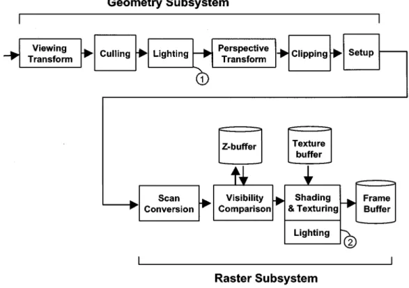
Fig. 1. Traditional 3-D graphics rendering pipeline.
II. BACKGROUND A. 3-D Graphics Rendering Pipeline
Polygon-based rendering is one of the mainstream methods to generate 3-D graphics. Its rendering job can generally be divided into two parts: 1) geometric subsystem and 2) raster subsystem. The geometry subsystem transforms the polygons in 3-D coordinates vertices, and then maps them into 2-D co-ordinates. Raster subsystem receives output of geometry sub-system, and renders the transformed polygons to generate final images for display. These two subsystems are pipelined for high throughput in general. Fig. 1 is an example of traditional 3-D Graphics rendering pipeline.
1) Transformations: As shown in Fig. 1, transformations are
major operations in geometric subsystem. It can be handled by 4 4 matrix operations. In 3-D graphics rendering, the essen-tial transformations are viewing and perspective. The viewing transformation transforms objects from the world space to the view space; while the perspective transformations transforms the view space to the projection space and then maps it into 2-D screen coordinates.
2) Culling and Clipping: Culling operation culls away
some invisible polygons to eliminate unnecessary operations, and back-faced culling is the most popular one. Back-faced culling utilizes the order of vertices to denote the polygon as front-faced or back-faced, and then filters out the back-faced polygons. Furthermore, it can cull away those polygons that are too small to display. On the other hand, clipping operation can discard the out-of-sight polygons. Because only polygons existed in view volume can be displayed on screen, the polygon located outside the boundaries are discarded.
Although back-faced culling and clipping can eliminate some invisible polygons; however, there are other invisible polygons that can be hidden somewhere because they may be fully cov-ered by each other. Hence, a lot of invisible polygons still reside in pipeline, and the visibility of these polygons can only be de-cided after visibility comparison.
3) Lighting: Lighting is an essential operation to calculate
illumination on assigned position by illumination model. In order to simulate lighting effect in the real world, illumination model is usually complex. Phong illumination model [19] is the popular one, which is expressed as
(1) where
intensity of the ambient light; intensity of the light source;
unit vector from pixel to the light source; normal vector of the pixel;
, where is the vector from the pixel to the viewer;
gloss to model the highlight;
coefficients to model the characteristic of the material.
In this equation, the third term as a specular term is related to exponentiation. Furthermore, each vector needs to be normal-ized before applying to this equation, and normalization requires calculation of reciprocal square root. Several attempts have been made to reduce lighting operations with Taylor series approxi-mation [12], [13] and angular interpolation [14], [15] being the two major ways. Although a lot of attempts had been made to
TABLE I
POLYGON-LEVEL ANDPIXEL-LEVELSHADINGPROCESS INTHREESHADINGMETHODS
solve this problem, lighting operation still remains the bottle-neck in 3-D graphics rendering. The lighting operation may be performed in the locations labeled by and , as shown in Fig. 1, while the real location depends on the shading scheme. We shall discuss this later.
4) Setup: Setup is the operation to prepare the necessary
in-formation for further rasterization in raster subsystem. In the setup operation, two kinds of data are generated. The first type is the data related to shape information, while the second one is related to color information.
Because triangles are described by vertices in geometry subsystem, the setup stage helps rasterize stage to scan-convert triangles into a group of pixels. Traditionally, the setup stage decomposes triangles into two scanline-aligned parts with each part being described by left-side edge, right-side edge, and maximal and minimal -coordinates boundaries. Regarding the setup for color information, the job of setup stage depends on the shading method.
5) Raster Subsystem: In conventional rendering pipeline,
raster subsystem handles rasterization. Rasterization consists of three subtasks: 1) scan conversion; 2) visibility comparison; and 3) shading. At the beginning of initiating raster subsystem, the scan conversion decouples polygon into several spans, and then generates a group of pixels. The groups of pixels denote the area that these triangles cover on display.
Hence, the operations before scan conversion are polygon-level operations, and they become the pixel-level operations after scan conversion. Shading operation colors each pixel for display, and texture mapping is also applied here. Visibility comparison determines the visibility of each pixel, and -test is the most common algorithm.
6) Shading: Shading is the operation to color each pixel
on display. Since lighting calculation is compute-intensive, it is appropriate to avoid applying lighting on all pixels. Hence, several shading methods have been developed, and three shading methods are generally utilized: flat shading, Gouraud shading and Phong shading. The simplest method is flat shading. It only applies lighting once for each polygon, and then shades all pixels inside this polygon with the same color. The number of lighting operations is smallest, but the image quality is very poor. Another method, Gouraud shading [20], can generate better image quality. It applies lighting on vertices of each polygon, and then shades each pixel inside polygon by interpolating color on vertices. Because it can render polygons with smooth color gradation, its result is more acceptable and
widely utilized today. However, it cannot produce highlight inside the polygons and suffers from Mach Band effect. Among the three methods, Phong shading [19] can generate the best image quality, but it needs a lot of calculations. In Phong shading, the lighting operation is applied to each pixel inside polygons. Several researchers have proposed to support Phong shading by hardware [16]–[18]. However, Phong shading is computation-intensive, and its hardware implementation costs a lot of chip size.
7) Relationship Between Lighting and Shading: In Table I,
we list the relationship between lighting and shading operation. As shown in Fig. 1, in both flat shading and Gouraud shading, lighting operation is executed in the box labeled , while in Phong shading the lighting operation is performed in box la-beled .
Among three shading schemes, the major difference is where the lighting operation is located in polygon-level or in pixel-level. In flat shading and Gouraud shading, lighting operations are in polygon-level, and therefore the number of lighting opera-tions is in proportion to polygon number. On the other hand, the number of lighting operations is related to the pixel number. Be-cause each polygon can be decomposed into dozens or hundreds of pixels, the number of lighting operations in Phong shading are dozens or hundreds times more than those in flat and Gouraud shading.
Hence, computation requirement is a tradeoff of image quality, and one of major reasons is attributed to the high computation requirement of lighting operations. Phong shading generates higher image quality but demands huge computation power. Real-time 3-D graphics makes this condition even worse, because rendering system needs to render 3-D scenes over 24 to 30 times/s. The lighting operation leads to two problems. The first problem is in the high-end system. Since Phong shading and high resolution are needed for high image quality, the total number of lighting operation is very huge and becomes a bottleneck, even though high-end system equips high computation power. On the other hand, the complexity of lighting calculation also leads to a problem in low-end system, even in the flat shading scheme. Because CPU handles lighting calculation in low-end system, the complexity of illumination equation causes large burden for CPU. It is infeasible to implement real-time 3-D graphics for consumer electronics, especially for some low-cost low-power portable devices.
8) Texturing: Texturing operation provides a simple method
im-ages stored in texture buffer onto the surface of specific poly-gons. In different modes for texturing, texture operation unit may fetch texture buffer 1, 2, 4, 8, or more times for each pixel. Therefore, huge bandwidth requirement is the major problem of texturing operation.
B. Observations on Traditional Rendering Pipeline
1) Invisible Polygons and Pixels: 3-D graphics rendering is
a process to render 3-D models into 2-D images. Because of reduction in dimension, a lot of information loses during this process. Hence, in 3-D graphics rendering, dimension reduction causes a lot of polygons and pixels to be invisible.
The polygon is a shape defined by vertices, and its size is very flexible. The reasons to make a polygon invisible may be attributed to the following: back-faced, outside the view volume, covered by other polygon or too small to display. Among these four reasons, back-faced and too small of polygons can be eliminated in culling operation, whereas the polygons outside the view volume are removed in clipping op-eration. However, the polygon fully covered by other polygon can only be decided after visibility comparison. Therefore, in traditional rendering pipeline, the operations in connection with fully covered polygon are unavoidable.
On the other hand, if a pixel is invisible, it is covered by an-other pixel with the same coordinates. Because of dimension re-duction, a lot of distinguished pixels in 3-D are projected into the same coordinates on 2-D screen; therefore, the ratio of invisible pixels is very high. However, in traditional rendering pipeline, the data flow for pixel operations are regular and straightfor-ward. Although invisible pixels can be discarded after visibility comparison, they still cause “bubbles” in pipeline, thus lowering the memory and hardware utilization.
2) Heterogeneous Data Flows in Pipeline: In traditional
rendering pipeline, another problem is generated due to het-erogeneous data flows. Polygon and pixel are major data types in rendering pipeline. However, there are dozens to hundreds times difference in terms of the numbers of data. Moreover, the sizes of polygon are various. The massive and irregular expansion on data amount causes problems in data flows.
Besides data amount, the operations on these two data flows have different attributions. In geometry subsystem, the data flow related to polygon requires a lot of computation power. The data flow in geometry subsystem is relatively regular, and generally needs no external memory access. On the other hand, the com-putation in raster subsystem is relatively simple. However, huge bandwidth is required, especially on depth buffer and texture buffer access.
Hence, in traditional rendering pipeline, some areas are com-putation-bound, and some areas are memory-access-bound. However, traditional method handles them in a long syn-chronous pipeline. Even you design to speed up the capability somewhere, but this speed-up may be cancelled in pipeline stall elsewhere.
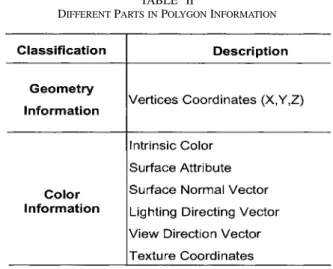
3) Different Types in Polygon Information: There are two
major parts in polygon information, as listed in Table II. The first part is related to geometry, which keeps the geometrical charac-teristics of a polygon in 3-D space. Hence the shape and depth of this polygon can be described. The second part of polygon
TABLE II
DIFFERENTPARTS INPOLYGONINFORMATION
information is related to color, and it describes how a polygon should be shaded, colored or textured. The lighting calculation needs to use the second part of polygon information.
Although two parts of polygon information have little rela-tionship, they are transferred together in traditional 3-D graphics rendering pipeline. This method cannot explore parallelism in data operations, and causes limitations when arranging opera-tions in pipeline.
C. Data Rate Changing in Pipeline
1) Types of Data Rate: Data rate dominates the behavior of
data flows in 3-D rendering pipeline. In order to discuses the characteristics between different designs, we can roughly clas-sify data rate in rendering pipeline into five major types: 1) tri-angle rate; 2) reduced tritri-angle rate; 3) pixel rate; 4) reduced pixel rate; and 5) scan-out rate.
“Triangle rate” is the data rate before scan conversion in rasterization. We call this data rate “triangle rate” instead of “polygon rate” because triangle is the major type of polygon in rendering pipeline. This rate is also a common benchmark to indicate how many triangles the hardware can handle within a period of time. “Reduced triangle rate” is a modified triangle rate after deleting invisible triangles. This rate seldom appears in previous architectures because it is hard to eliminate invisible triangles in the traditional rendering pipeline.
“Pixel rate” is the data rate rendered after scan conversion and before visible comparison. In scan conversion, each polygon is converted into dozens to hundreds of pixels. Hence, the data rate increases dozens to hundreds times more as compared with tri-angle rate. On the other hand, “reduced pixel rate” is the data rate after visible comparison. In the area of reduced pixel rate, pixels that fail in visibility comparison are discarded, and there-fore the data rate is reduced.
“Scan-out rate” is related to the scan-out mechanism. In order to illustrate image data, the pixel values in frame buffer must be scan-out for display. Generally speaking, scan-out proceeds after the entire rendering task is finished, and hence the visible pixels on display are fixed. This rate is relatively steady.
This classification can be utilized for the analysis on band-width and calculation. Besides scan-out rate, other four data rate is related to complexity of 3-D scene. On the other hand,
Fig. 2. Illustration of data flow in different rendering pipelines: (a) traditional; (b) deferred shading; (c) index rendering, depth value stored in and
I-buffer; (d) index rendering, depth value stored in Z-buffer.
scan-out rate is much different. It is related to screen coordi-nates and is not affected by scene complexity.
2) Data Rates in Traditional Rendering Pipeline: Fig. 2(a)
shows the data flow and data rate in traditional rendering pipeline. Different gray levels are used to shade different areas of data rates. The shaded area can show how the data rate affects the operations. If an operation falls in one data rate area, it means that the total operation number is related to the data rate. Because the position for lighting operation depends on shading scheme, two lighting blocks are shown in this illustration and labeled with different marks. In flat shading and Gouraud shading, lighting operation is in the box labeled , while in Phong shading the lighting operation is performed in box labeled .
The entire geometry subsystem runs in triangle rate. The scan conversion is the bridge between triangle rate and pixel rate. The visibility comparison works in pixel rate. Generally speaking, the shading and texture operations can be placed before or after visibility comparison in rendering pipeline, which may be running in either pixel rate or reduced pixel rate. This option depends on the hardware architecture designer. Because the number of operation is smaller when running in reduced pixel rate, we place the shading and texture operations in reduced pixel rate in Fig. 2(a).
Generally speaking, the relationships of different data rates are
Pixel Rate Reduced Pixel Rate Triangle Rate Reduced Triangle Rate.
On the other hand, scan-out rate is directly proportional to the resolution of display and refresh rate. The lower the display resolution, the smaller is the scan-out rate. In general case, the scan-out rate is much smaller than both pixel rate and reduced pixel rate, because most pixels on display cover a lot of invisible pixels. On the other hand, there is no significant relationship between scan-out rate and triangle rate. The relationships among scan-out rate, pixel rate, and reduced pixel rate are
Pixel Rate Reduced Pixel Rate Scan-out Rate. Fig. 2(a) we can also see the effect of data rate on bandwidth. The arrow labeled means one data bus related to triangle rate. In the same way, denotes the pixel rate, denotes the re-duced pixel rate, and means scan-out rate. Because and are the areas of high data rate in general case, we fill up the arrows with black and gray colors. Furthermore, the arrow that points to texture buffer is labeled “ ,” because data of texture buffer is loaded before rendering.
D. Deferred Shading
In traditional rendering pipeline, shading and texture opera-tions fall in pixel or reduced pixel rates. This can be extravagant since a lot of shaded and textured pixels are covered in final image. Moreover, a lot of texture bandwidth is wasted on hidden pixels. In order to avoid this redundancy, a method of deferred shading was proposed. This architecture was first proposed in Deering’s Triangle Processor and Normal Vector Shader [9], and implemented in PROOF [10], Pixel-Planes 5 [1], and Pix-elFlow [2], [11]. This approach defers the shading and texture operations until the entire image has been rendered. Because the visibilities of all pixels are determined, only visible pixels on the final image can be shaded and textured. Therefore, this approach can eliminate unnecessary operations on hidden pixel, and makes the pixel-level operations computation-effective. The data flow in deferred shading approach is illustrated in Fig. 2(b). The shading and texturing operations are moved into the area of scan-out rate, and hence the number of total operations reduced. However, in order to support the deferred shading, the func-tion of frame buffer changes, which leads to buffer size and bandwidth problems. In traditional pipeline, the frame buffer keeps the results, the RGB color values of each pixel, after the shade and texture operations. Typically, 16–32 bits are required
to store a pixel in frame buffer. On the other hand, in deferred shading approach, because all pixels are not shaded and tex-tured before final scan-out, a screen-size pixel buffer is needed to store all information for further shading and texturing opera-tions. Since shading and texture parameters often over 100–200 for one pixel, the approach of deferred shading requires large screen-size pixel buffer and high bandwidth.
Why does the approach of deferred shading cause huge buffer and bandwidth requirement? The problems are caused by the parameters associated with shading and texturing. These parameters are related to original triangle such as and . In traditional rendering pipeline, all pixels belong to a triangle are shaded and textured one by one. Within a period of time, the shading and texture units handle a group of pixels from the same triangle. There is a temporal locality on pixel information. Hence, the parameters can be kept in shading and texture hardware for reuse. However, in deferred shading approach, shading and texture operations are in the area of scan-out. This temporal locality is broken. Each pixel needs to carry a copy of parameters of original triangle up to shading and texture operations. Therefore, although deferred shading approach can reduce shading and texture operations, it pays tradeoffs for occupying large-sized screen pixel buffer, and huge bandwidth.
Furthermore, the advantage on shading operation is limited. The advantage of deferred shading benefits mostly only to Phong shading, but little to flat and Gouraud shading. This condition is caused by the location of lighting. Because of complex illumination equation, lighting is the most com-putation-intensive task in shading operation. Lighting in Phong shading appears at pixel-level, whereas it appears at polygon-level in flat and Gouraud shading, as shown in Table I. Because deferred shading approach reduces pixel-level shading operations, lighting can be eliminated only in Phong shading, but it cannot be eliminated in flat and Gouraud shading. Therefore, the advantage of deferred shading cannot reduce lighting calculations for flat and Gouraud shading.
III. INDEXRENDERING
To retain the advantages of deferred shading without its drawbacks being attached, we propose a novel approach named index rendering. This approach requires less buffer size and bandwidth than that in deferred shading. Moreover, we utilize our deferred lighting technique for the architecture design, and hence we can eliminate unnecessary lighting operations for all kinds of shading methods. Hence, index rendering is a hardware-efficient architecture, and it can be utilized in real-time 3-D graphics rendering in both high-performance and low-end systems.
A. Concepts of Index Rendering
The first concept of index rendering is fetching and gen-erating pixel information on demand. Instead of transferring pixel information in graphics pipeline, we fetch and generate them when needed. Therefore, each pixel does not need to carry huge information through both the area of pixel rate
and the screen-size pixel buffer. This avoids high bandwidth and large screen-size pixel buffer in the graphics pipeline. To fetch pixel information from buffer, we use index as a key. Index is a serial number of triangles in current 3-D scene, and each pixel from the same triangle carries the same index number. Therefore, only the index is saved in the screen-size buffer, and only 10–20 bits are required for each pixel. In index rendering approach the screen-size buffer is named -buffer (index buffer). The triangle information for shading and texture operations are stored in another buffer to be named (triangle data base for shading). When shading and texture mapping are performed, each pixel can fetch parameters from its parent triangle via the index obtained from . Hence, with , the approach of index rendering only needs to store just one copy of triangle parameter for each triangle. Unlike deferred shading approach, the parameter of one triangle may be duplicated into a lot of copies for all visible pixels. Hence the buffer size becomes greatly reduced in index rendering than in deferred shading.
Index rendering not only defers shading, but also defers lighting. We propose deferred lighting in [22], and it is the second concept of index rendering approach. Table I shows that the lighting is polygon-level operation in flat and Gouraud shading. As discussed in deferred shading, we know deferred shading approach cannot reduce polygon-level operations, and therefore the lighting operations cannot be eliminated in flat and Gouraud shading. However, in index rendering approach, it is possible to defer polygon-level operations. The shading and texture parameters are stored in , which can only be fetched when scanned out. Because the parameters in are ineffective before all pixels in a 3-D scene are processed, the operations to generate parameters for can be asyn-chronous. Hence, for each triangle, the lighting operation can be deferred until the visibility of this polygon is decided. Therefore lighting operation on invisible polygon can be saved. In order to support these concepts, index rendering divides triangle information into several parts and handles them asyn-chronous. In general, there are two major parts in pixel informa-tion: The first one is related to geometry, which keeps the geo-metrical characteristics of a polygon in the 3-D space. This part can be further divided into -related and -related. -re-lated geometric information describes the shape of a polygon on display, whereas -related geometric information denotes depth. The second part of pixel information is related to color, which describes how a polygon should be shaded, colored or textured. Index rendering can handle each part of pixel information sep-arately and asynchronously, and index is the key to reunite all information to generate final result in shading operation.
B. Architecture of Index Rendering
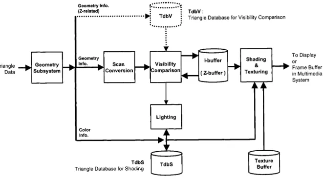
In this section, a new architecture for index rendering is pro-posed as shown in Fig. 3. (An earlier architecture of index ren-dering without deferred lighting was proposed in a previous paper [23].) This new architecture we propose is to realize raster subsystem in multimedia system. It receives and renders trian-gles to generate 3-D scenes, and then it outputs result to the integrated multimedia system. Its external interface is very sim-ilar to traditional rendering pipeline, and hence this approach
Fig. 3. Architecture of index rendering.
is compatible to the conventional 3-D graphics module in inte-grated multimedia system.
Fig. 3 shows the major blocks of index rendering. The block labeled by dotted line is optional when using different methods of visibility comparison. In order to render 3-D graphics image, each triangle is assigned to a unique index number. After passing the operations in geometry subsystem, the triangle information is separated into several parts and sent to different modules. The part related to color is sent to (triangle database for shading), and the part related to geometry is sent to scan conversion block. In scan conversion block, the polygon is decomposed into a group of pixels with index number and depth values. Then, visibility comparison tests the depth of pixels, and records the index number of visible pixels in -buffer. After whole polygon is scan-converted, visibility signal of the polygon is sent to lighting block. If the polygon is visible, lighting block carries on polygon-level shading operations for this polygon. Operations of lighting block can be asynchronous with that of scan conversion block to optimize data flow. The shading and texturing block will not fetch data in -buffer and to generate the final image until all polygons in a 3-D scene are scan-converted into -buffer and all triangle information in are ready.
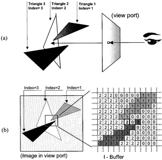
1) -Buffer: The -buffer (index buffer) plays an important
role in index rendering. It is a screen-size buffer to store index number. For each pixel on screen, -buffer records the index of triangle nearest to view port. That is, for each position on screen coordinates, the -buffer records which triangle to intersect with its tracing ray. Hence this buffer stores the index pattern of first-order ray tracing, as shown in Fig. 4.
2) Triangle Databases: Triangle databases are buffers to
store triangle information of which it is addressed by index number. Because index number dominates address space, the size of triangle database is related to maximal index number.
Therefore, maximal index number is an important term in design specification, and it limits the maximal visible triangle number in a 3-D scene. Because the triangle information is separated for asynchronous operations, there are different types of triangle database to store each part of triangle information: one is related to geometry, whereas the other is related to color. The color information is stored in . The geometric information can be further divided into -related and -related. -related geometric information is utilized in scan-conversion block to generate the shape of polygons, not necessarily to be stored. -related geometric information is sent to scan-conversion block to generate pixel depth, but it also needs to be stored in (triangle database for visibility comparison) if visibility comparison without -buffer is required. We shall discuss this in next subsection.
For example, if we synthesize 3-D scene by Gouraud shading with texture mapping, the typical information in each database is listed in Table III.
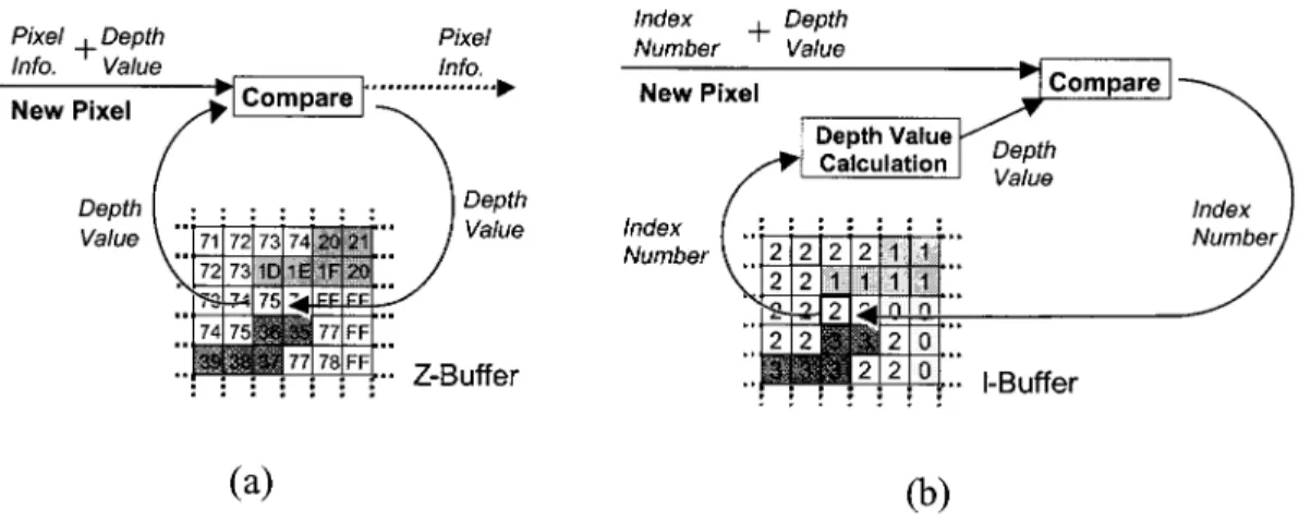
3) Visibility Comparison: Visibility comparison is a process
to remove hidden pixels by using their depth values. -buffer algorithm is the most common method for visibility compar-ison. In -buffer algorithm, visibility comparison unit receives a pixel containing both depth value and current coordinates, and then it fetches the related depth value from -buffer. After comparing the depth value, nearest depth value will be kept in -buffer. In index rendering, we can employ the -buffer al-gorithm for depth comparison, and the design of -buffer en-tries is coexistent with -buffer, as shown in Fig. 5. Therefore both -buffer and -buffer can be fetched and stored at the same time. Whenever a new pixel passes the visibility compar-ison, both -buffer and -buffer are updated at the same time. If -buffer exists in index rendering architecture, is not needed, and therefore the dotted box and dotted lines in Fig. 3 are unnecessary.
Fig. 4. Illustration for index buffer (I-buffer): (a) first-order ray-tracing and (b) data stored in I-buffer. TABLE III
TYPICALINFORMATION INTRIANGLEDATABASE FORGOURAUDSHADING
Fig. 5. Buffer entry ofZ-buffer and I-buffer.
On the other hand, index rendering can also realize visibility comparison without -buffer. The depth value, , can be gen-erated by linear expression as follows:
(2)
The parameters and are stored in .
Because the -buffer keeps the index number of visible pixel, -buffer can replace the functions of -buffer. The operation of depth comparison by different methods is illustrated in Fig. 6. Depth value is fetched directly from -buffer by conventional method, but it is real-time generated from linear expression by second method.
4) Lighting: Lighting operation calculates illumination in
a 3-D scene by illumination model. In conventional rendering pipeline for flat or Gouraud shading, lighting operation locates
Fig. 6. Temporal storage for visibility comparison: (a) depth value stored inZ-buffer and (b) depth value stored in andI-buffer. in geometry subsystem, and it does not appear in raster
sub-system. Nevertheless, since our index rendering can eliminate the redundant lighting operations by deferred lighting, we place this unit in our architecture in order to demonstrate the feasi-bility of this lighting operation. The data path from visifeasi-bility comparison block to lighting block is the key in terms of de-ferred lighting design, as shown in Fig. 3. It transmits a signal to indicate whether current polygon is visible or not. If all pixels of one polygon fail in visibility comparison, this polygon is invis-ible. Hence lighting calculation on this invisible triangle is un-necessary, and the information of this triangle can be discarded. This architecture is applicable for three shading methods. For flat and Gouraud shading, lighting is applied for polygon-level. If a new polygon is received and its index number is , its color information is temporarily stored in -th entry of , and lighting is deferred until the signal is identified for its visibility. If this signal shows that polygon is visible, the data in -th entry of will be read into lighting block for lighting calcula-tion, and the result is written back into the original entry. On the other hand, if this signal indicates that polygon is invisible, this polygon information will be discarded. The index number can be reassigned and the space of -th entry in can be freed for another polygon. Hence, triangle database only keeps the visible triangles in a 3-D scene.
Furthermore, in Phong shading, lighting calculation is ap-plied at pixel-level. Therefore, lighting is deferred until final scan-out. In this case, the parameter for shading is still stored in . If one pixel needs to be shaded, and its index number is , the data of -th entry of is sent to lighting block. After lighting calculation, the result is sent to shading block to gen-erate final result.
5) Shading and Texturing: Shading and texturing block
generates color for each pixel. As for shading, in flat shading, the shading block can directly fill the pixel with the uniform color of its parent triangle, and the color value is stored in . In Gouraud shading, color interpolation is nec-essary. The linear expression is applied to calculate each value, and all necessary parameters are fetched from . For example, in order to shade pixel by Gouraud shading, we check index number stored in coordinates in -buffer. If this index number is , we can find out the polygon information of -th triangle in , such as
and .
Than, the color of this pixel can be calculated from the fol-lowing linear expressions:
(3) On the other hand, Phong shading interpolates normal vectors and applies lighting on each pixel. In this case, the linear expres-sion is also capable of interpolating vectors, and can store the parameters for vector interpolations. If Taylor series approx-imation is utilized, becomes the storage of parameters for Taylor series.
On the other hand, the texture coordinates can also be gen-erated by linear expressions. With coordinates, we can fetch texture buffer for texture mapping. Because the texturing operation is in scan-out rate now, it can avoid a lot of redundant fetching on texture buffer resulted from the absence of invisible pixels. The linear expressions for texture coordinates generation are as follows:
(4)
6) Scan Conversion: In index rendering, since shading
op-eration is deferred, the scan conversion becomes light-weighted. The major task of scan conversion is to issue pixels inside the shape of triangle. Because we use -buffer algorithm for visibility comparison, the calculation of depth value is needed in scan conversion. In general case, depth value can be generated by simple calculation of addition. Each pixel issued from scan conversion carries index number, depth value, and its coordinates only. Hence, high-speed scan conversion can be achieved and parallel algorithms can be employed, such as Pineda’s parallel polygon rasterization algorithm [24].
C. Data Flow in Index Rendering
The data flow and data rate of index rendering are illustrated in Fig. 2(c) and (d). Both architectures of Fig. 2(c) and (d) are ap-proaches of index rendering, and their difference is the method
TABLE IV
HARDWARELEVELS FORANALYSIS ANDSIMULATION
TABLE V
TRIANGLENUMBERS OF3-D OBJECTS
to store depth value. In Fig. 2(c), both -buffer and are used to store the depth value. In Fig. 2(d), the depth value is stored in -buffer.
Besides the advantage of placing shading and texturing op-erations in scan-out rate, there are two key points in the data flow of index rendering: The first one is the design of -buffer and . Because of this design, we can replace the huge and high-bandwidth pixel buffer with small and low-bandwidth buffers, -buffer, and . Therefore, the approach of index rendering can employ the advantage of deferred shading without suffering from its drawbacks.
Moreover, we can reduce the number of lighting operations, even in Gouraud and flat shading methods. The reason is that the approach of index rendering moves the lighting operation from geometry subsystem into the area of “reduced triangle rate,” and this is the second key point.
IV. ANALYSIS ANDSIMULATION
For further analysis and simulation, reasonable assumptions are needed to demonstrate the outcome generated from the is-sues discussed in this paper. We discuss three architectures: tra-ditional, deferred shading and index rendering. When realizing 3-D graphics on hardware, cost is an important issue. Therefore we roughly classify the capability of 3-D graphics hardware into three levels: 1) high-performance; 2) middle-performance; and 3) low-end. Furthermore, to show the reduction of lighting cal-culation, we simulate several 3-D objects with different resolu-tions and shading methods to show the capability of three archi-tectures.
A. Analysis Parameters
1) Hardware Levels: For simulation, we roughly classify
the capability of 3-D graphics into three levels: 1) high-perfor-mance; 2) middle-perforhigh-perfor-mance; and 3) low-end. Assumptions
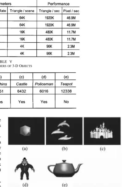
Fig. 7. Three-dimensional objects for simulation.
of three hardware levels are listed in Table IV. The major difference of three levels is the complexity of 3-D scene. The high-performance approach renders about 2M triangles/s. The middle-performance approach focuses on game and entertain-ment areas and targets on 480 K triangles/s. In the low-end approach, such as portable devices or PDA, 3-D graphics can be utilized as user interface, and its performance targets on 96 K triangle/s.
The second difference is the resolution. For each hardware level, we discuss two kinds of screen resolution; therefore, we can find how differently the resolutions can affect the result. Resolution 800 600 appears both on high-performance and middle-performance levels to find how the complexity of 3-D scene affects results under the same resolution. The third dif-ference is frame rate. Because of persistence of human vision, higher frame rate is not necessary in general case. We assume that the frame rate is 30 in high- and middle-performance levels and it is 24 in low-end.
Fig. 8. Four types of architecture: (a) Type (traditional pipeline); (b) Type (deferred shading); (c) Type (index rendering, depth value stored in and
TABLE VI
SUMMARY OFVARIABLES FORANALYSIS ANDSIMULATION
2) Simulation Patterns: In order to simulate the behavior of
index rendering, we have utilized the Java [26] and Mesa [27] to develop our simulation environment. Mesa helps to handle the operations in geometry subsystem. It is capable of converting 3-D models into a lot of scanline-aligned triangles. Then, we write java programs to render the final images and to count the data rate. Hence we can get the information for analysis. In order to reflect the real case, we simulate the 3-D models to un-derstand their requirements in data rate. Then, we utilize them to analyze the computation, buffer size and bandwidth require-ments in hardware. Fig. 7 shows the 3-D objects for simulation patterns, and their triangle numbers are listed in Table V. The original resolution of 3-D objects is 640 480. For different res-olutions, we scale these object models in order to control vari-ables. For example, if we need to simulate 3-D scene in resolu-tion 320 200, all object models are scaled into 0.5. In order to show the real reduction on triangle, we enable GL CULL FACE when generating intermediate simulation patterns except Poly-hedron. Hence, the 3-D objects (b)-(d) are back-face culled be-fore simulation, so the simulation can present more to reflect the real result caused by architecture designs.
Among five 3-D objects, the first one is Polyhedron with two colored triangles to simulate the 3-D objects at user interface for low-end system. The 3-D objects (b)-(d) are taken from the sample files of OpenGL developer tools of SGI [25]. Those models show the general objects in 3-D applications. “Dolphins” and “Policeman” illustrate the shape of animal and human. The bodies of “Dolphins” are simple and smooth, whereas the model of “Policeman” is complex and it consists of many parts. “Castle” is another model of different type with many walls cover each other, causing a lot of pixels in this model to become invisible. In order to simulate the condition in today’s 3-D applications, these three models are back-face culled. “Teapot” is generated by function glutSolidTeapot( ) in Mesa, and modeled by a lot of small triangles. In high-perfor-mance system, most 3-D objects are modeled by a lot of small triangles to present curvy surface smoothly, and hence “Teapot” can simulate this condition in high-performance system.
3) Architecture Types: In the following analysis and
sim-ulation, we compare four architectures (Types – ). Type is the traditional rendering pipeline, and it equips the frame buffer and -buffer. Type is deferred shading. For fair com-parison, we use the direct method to model deferred shading in order to show its essential characteristics. This architecture needs -buffer for visibility comparison and pixel buffer to keep information for each pixel on screen. Type and are
approaches of index rendering with different methods of visi-bility comparison. Type utilizes -buffer and to gen-erate depth value in real-time, while Type uses conventional -buffer to store depth value temporally. Four architectures are illustrated in Fig. 8. There are additional notations in Fig. 8(a), (b) to show where the lighting operation is executed. In flat shading and Gouraud shading, lighting operation is in the box labeled , while in Phong shading the lighting operation is per-formed in box labeled .
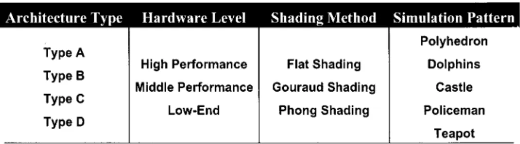
We summarize all four variables for analysis and simulation in Table VI. These four variables are: 1) architecture type; 2) hardware level; 3) shading method; and 4) simulation patterns.
B. Numbers of Lighting and Texture Operations
1) Numbers of Lighting Operation: The major advantage of
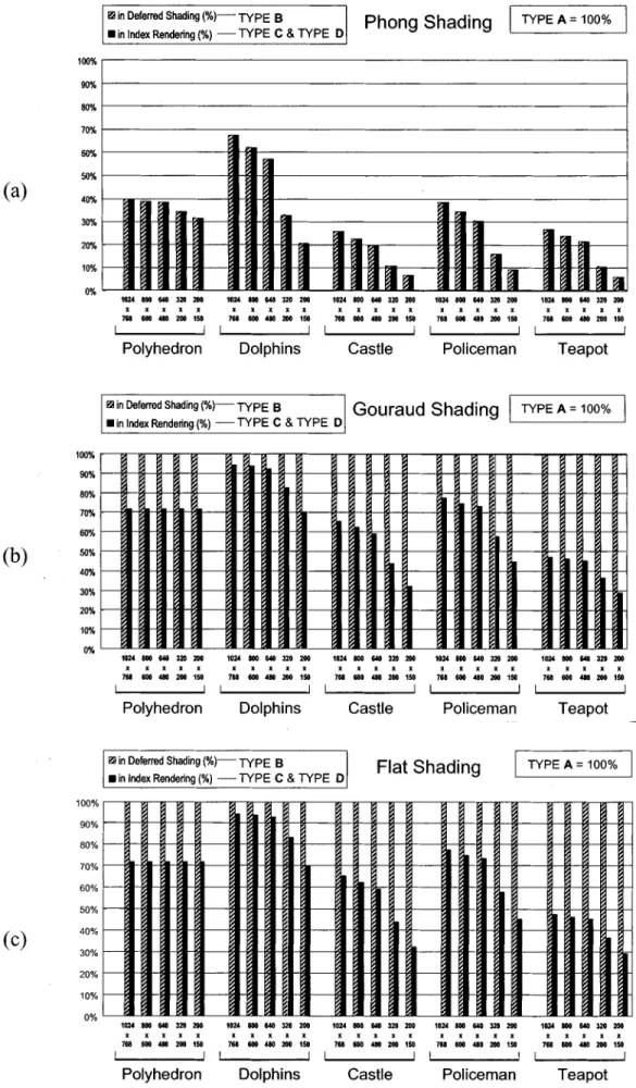
index rendering and deferred shading is the reduction of lighting operation. Fig. 9 shows the simulation result for numbers of lighting operation, which is compared with traditional rendering method (Type ). We set the number of lighting operations in Type as 100% in Fig. 9. In this figure, both types of index rendering (Type ) have the same results, because the method of visibility comparison is not related to the number of lighting operation. Therefore, we only illustrate two data on each trial: deferred shading (Type ) and index rendering (Type ).
2) Lighting in Phong Shading: As shown in Fig. 9(a), we
can find that deferred shading and index rendering reduce the same number of lighting operations, about 30% to 95%. This re-duction becomes larger for complex 3-D objects and lower reso-lution. The reasons are that complex 3-D objects have more cov-ered pixels in their model, and lower resolution leads to fewer visible pixels. Fig. 9(a) shows that deferred shading has sig-nificant improvement in Phong shading, and therefore we can know why some high-end 3-D hardware uses deferred shading to solve computation bottleneck, though it costs a lot on buffer size and bandwidth. With the same reduction in lighting opera-tions, index rendering can provide better solution to solve this bottleneck with less cost.
3) Lighting in Gouraud and Flat Shading: However,
deferred shading approach can not reduce lighting operations in flat shading and Gouraud shading, and hence the proportion of lighting number remains in 100% compared with traditional rendering pipeline (Type ), as shown in Fig. 9(b) and (c). On the other hand, because of the technique of deferred lighting, index rendering can reduce 10%–70% of lighting operation in flat and Gouraud shading. Complex models and lower resolutions also lead to better reduction, but the model of
TABLE VII
RELATIONSHIP OFARCHITECTURES, BUFFERS ANDPARAMETERS
Polyhedron is an exception. Polyhedron is constructed by quite large polygons, and the visibility of each triangle remains the same at different resolutions. Therefore, its lighting number does not change in low resolution because the reduction caused by deferred lighting is related to invisible polygons. Furthermore, although the proportions of lighting numbers of flat and Gouraud shading are the same in the figure, the original lighting number in Gouraud shading is three times more than that in flat shading. Therefore, the reduction is more significant in Gouraud shading.
4) Lighting Operation Number and Data Rate: In fact, the
reduction on lighting operation number is related to the data rate. Referring to Fig. 2, we can find that: as for Phong shading, the lighting operation is located in the area of reduced pixel rate in traditional pipeline. On the other hand, the lighting operation is in the area of scan-out rate area in both deferred shading and index rendering approach. Hence, the Fig. 9(a) can be treated as comparison between “reduce pixel rate” and “scan-out rate.”
On the part of Gouraud and flat shading, the lighting operation is located in the area of triangle in previous ar-chitectures, including both traditional pipeline and deferred shading approach. Hence deferred shading approach cannot reduce number of lighting operation. However, because of the technique of deferred lighting, index rendering approach can move the lighting operation into the area of reduced triangle rate. Therefore, Fig. 9(b) and (c) is also the result of comparing “triangle rate” and “reduced triangle rate.” Moreover, because most models are back-face culled before simulation, the result can reflect the real reduction of lighting operation.
5) Number of Texture Operation: Referring to Fig. 2, in
tra-ditional rendering pipeline, the texture operation is in the area of reduced pixel rate. However, in deferred shading approach, it is moved to the area of scan-out rate. Hence, the reductions on texture operation and texture buffer bandwidth are also the ad-vantages of defer shading approach. Index rendering approach retains the advantages. Therefore, for comparisons of both
oper-ation and of bandwidth, the results are also the comparison be-tween “reduce pixel rate” and “scan-out rate.” Their percentage figures are the same as Fig. 9(a).
C. Buffer Analysis
1) Buffer Size: The characteristic of each kind of buffer
is listed in Table VII, and relationships between different architectures and buffers are marked. Among six kinds of buffers, resolution affects the size of -buffer, frame buffer, pixel buffer and -buffer. Scene complexity affects the size of two triangle databases and because triangle databases must keep information of all visible polygons on screen. Furthermore, scene complexity also affects -buffer, because the length of index equals to (maximal visible polygon number in a scene) . Within both approaches of deferred shading and index rendering, color information should be stored for shading operations, and hence it affects the size of pixel buffer and . We do not discuss the size of texture buffer here because its size is user-defined, and there is no direct relation with other simulation parameters, such as screen resolution and scene complexity.
Fig. 10 shows the buffer size of four architectures, and con-tribution of each type of buffer is labeled. Generally speaking, buffer size is larger in Phong shading than in Gouraud shading. The lower the resolution, the smaller is the buffer size. Among all kinds of buffers, the size of pixel buffer is the largest re-gardless of architecture type. Therefore, it makes overall buffer size huge in deferred shading (Type ), especially in Phong shading. The overall buffer size in deferred shading grows up quickly with increasing resolution, and it becomes several times more than that in traditional rendering pipeline (Type ). On the other hand, because index rendering (Type ) uses the con-cept of fetching and generating pixel information on demand, the overall buffer size is as small as Type . Therefore, index rendering is more cost effective and feasible in the architectures of low-cost systems.
Fig. 10. Buffer sizes in four types of architecture: (a) Phong shading and (b) Gouraud shading.
Fig. 11. Analysis of maximum bandwidth: (a) Phong shading and (b) Gouraud shading. 2) Maximum Bandwidth Analysis: Fig. 11 shows the result
of bandwidth analysis for worst case. In the worst case scenario, we assume an animated 3-D scene that has maximal allowed polygon number of current architecture where all polygons are
visible in each frame by rendering it in real-time to see its ani-mation. This analysis can show the maximal bandwidth require-ment. Among all types of architectures, the bandwidth of tradi-tional rendering pipeline (Type ) is relatively small, but pixel
Fig. 12. Buffer bandwidth by simulation (a) Phong Shading, (b) Gouraud shading.
buffer in deferred shading has the largest bandwidth. Due to high bandwidth on large-sized buffer, pixel buffer becomes the bot-tleneck of deferred shading.
To solve this problem, index rendering uses two different strategies. The first one is to map high bandwidth access in a very small buffer, and makes this buffer small enough to be
em-bedded on-chip to reduce cost effectively. Since on-chip buffer can support high bandwidth, using this architectural design can solve the limitation on bandwidth. This strategy is used in our Type architecture. Although the bandwidth of is huge, and makes total bandwidth larger than deferred shading in some case, the size of is small enough to be embedded on-chip, as shown in Fig. 10. The size of is about 720 kB in high-performance, 168 kB in middle-performance, or 30 kB in low-end system. Hence, this buffer is small enough to be implemented cost-effectively by high-speed buffer, such as an embedded memory. Without the bandwidth of , the re-mained bandwidth is much smaller than deferred shading. The second strategy is to reduce the bandwidth directly by archi-tectural design, and Type uses this strategy. Type employs index rendering, but utilizes traditional -buffer for visibility comparison. This method cannot optimize bandwidth with small high-speed buffer, but it has the capability to avoid high band-width caused by . This approach can also reduce the high bandwidth existed in deferred shading.
3) Bandwidth Simulation: In order to show bandwidth in
real cases, we simulate 3-D models to see how it changes. Only the overall bandwidth is illustrated in Fig. 12 to simplify the figures. Among different types of architectures, traditional ren-dering pipeline (Type ) requires smallest bandwidth, while deferred shading (Type ) requires the largest. In this figure, we find index rendering approaches (Type ) greatly reduce bandwidth in simple 3-D objects, such as Polyhedron and Dol-phins. In complex 3-D objects, the bandwidth in index rendering is still smaller than that in deferred shading. Although Type also requires high bandwidth in some cases, small high-speed buffer can solve this problem. Type is similar in low band-width to Type , and hence this architecture is a more cost-ef-fective method to realize index rendering.
V. CONCLUSION
In this paper, we propose a novel approach, index rendering, and its referential architecture for 3-D graphics rendering. This approach retains the advantage of deferred shading and elim-inates its drawbacks. The basic concepts of index rendering are “fetching and generating pixel information on demand” and “deferred lighting.” To support these concepts, index rendering separates pixel information into several parts and handles them asynchronously. The result shows index rendering can elimi-nate 10%–70% lighting operations in flat and Gouraud shading, and 30%–95% in Phong shading. Furthermore, it saves 70% buffer size and 50%–70% bandwidth as compared with deferred shading.
According to the analysis and simulation results, index rendering is hardware-efficient, and especially suitable for high-performance and low-end rendering systems. In the high-performance system, index rendering can reduce the same lighting and texture operations as deferred shading, but it requires smaller buffer and lower bandwidth. In the low-end system, index rendering can significantly reduce lighting op-erations in flat shading and Gouraud shading with the costs of buffer and bandwidth being acceptable (buffer size 130 kB–224 kB, bandwidth 15 MB/s–81 MB/s). Hence, index rendering can
make 3-D graphics feasible in low-end systems and portable devices, such as mobile phone, PDA, etc. About antialiasing and transparency, Mammen’s method [28] can be employed in index rendering. Hence, index rendering is capable of making 3-D rendering hardware-efficient and it is easy to be integrated into multimedia system of today, both in high-performance and low-end systems, especially suitable in system-on-a-chip (SOC) design.
ACKNOWLEDGMENT
The authors would like to acknowledge the valuable sugges-tions from the reviewers and the associate editor.
REFERENCES
[1] H. Fuchs et al., “Pixel-planes 5: A heterogeneous multiprocessor graphics system using processor-enhanced memories,” in Proc.
SIG-GRAPH, 1989, pp. 79–88.
[2] S. Molnar, J. Eyles, and J. Poulton, “PixelFlow: High-speed rendering using image composition,” in Proc. SIGGRAPH, 1992, pp. 231–240. [3] K. Akeley, “Reality engine graphics,” in Proc. SIGGRAPH, 1993, pp.
109–116.
[4] J. Montrym et al., “InfiniteReality: A real-time graphics system,” in
Proc. SIGGRAPH, 1997, pp. 293–301.
[5] T. Ikedo and J. Ma, “The Truga001: A scalable rendering processor,”
IEEE Comput. Graph. Appl., vol. 18, pp. 59–79, Mar. 1998.
[6] J. McCormack et al., “Neon: A single-chip 3-D workstation graphics ac-celerator,” in Proc. EUROGRAPHICS/SIGGRAPH Workshop Graphics
Hardware, 1998, pp. 123–132.
[7] J. Torborg and J. T. Kajiya, “Talisman: Commodity realtime 3-D graphics for the PC,” in Proc. SIGGRAPH, 1996, pp. 353–363. [8] A. C. Barkans, “High-quality rendering using the talisman
architec-ture,” in Proc. EURO-GRAPHICS/SIGGRAPH Workshop Graphics
Hardware, 1997, pp. 79–88.
[9] M. Deering et al., “The triangle processor and normal vector shader: A VLSI system for high-performance graphics,” in Proc. SIGGRAPH, 1988, pp. 21–30.
[10] B.-O. Schneider and U. Claussen, “Proof: An architecture for rendering in object space,” in Advances in Computer Graphics Hardware III, A. A. M. Kuijk, Ed. New York: Springer-Verlag, 1991, pp. 121–135. Eu-rographics Seminars.
[11] J. Eyles et al., “PixelFlow: The realization,” in Proc.
EURO-GRAPHICS/SIGGRAPH Workshop Graphics Hardware, 1997, pp.
57–68.
[12] T. Duff, “Smoothly shaded renderings of polyhedral objects on raster displays,” Comput. Graph., pp. 270–275, 1979.
[13] G. Bishop and D. M. Weimar, “Fast Phong shading,” Comput. Graph., pp. 103–106, 1986.
[14] A. M. Kuijk and E. M. Blake, “Fast Phong shading via angular interpo-lation,” Comput. Graph. Forum, vol. 8, pp. 315–324, 1989.
[15] U. Clausen, “Reducing the Phong shading method,” in Proc.
EURO-GRAPHICS, 1989, pp. 333–344.
[16] T. Ikedo and J. Ma, “An advance graphics chip with bump-mapped Phong shading,” in Proc. Int. Computer Graphics, 1997, pp. 156–165. [17] C.-L. Chen, B.-S. Liang, and C.-W. Jen, “A low-cost raster engine for
video game, multimedia PC, and interactive PC,” IEEE Trans. Consumer
Electron., vol. 41, pp. 724–730, Aug. 1995.
[18] H.-C. Shin, J.-A. Lee, and L.-S. Kim, “A minimized hardware archi-tecture of fast Phong shader using Taylor series approximation in 3-D graphics,” in Proc. Int. Conf. Computer Design, 1998, pp. 286–291. [19] B. T. Phong, “Illumination for computer generated pictures,” Commun.
ACM, vol. 18, pp. 311–317, June 1975.
[20] H. Gouraud, “Continuous shading of curved surfaces,” IEEE Trans.
Comput., vol. C-20, pp. 623–629, June 1975.
[21] H. Fuchs et al., “Fast spheres, shadows, textures, transparencies, and image enhancements in pixel-planes,” in Proc. SIGGRAPH, vol. 19, July 1985, pp. 111–120.
[22] B.-S. Liang, W.-C. Yeh, Y.-C. Lee, and C.-W. Jen, “Deferred lighting: A computation-efficient approach for 3-D graphics",” Proc. IEEE Int.
[23] B.-S. Liang, Y.-C. Lee, W.-C. Yeh, and C.-W. Jen, “Index rendering: A hardware-efficient architecture for 3-D graphics,” in Proc. VLSI
De-sign/CAD Symp., 1999, pp. 137–140.
[24] J. Pineda, “A parallel algorithm for polygon rasterization,” in Proc.
SIG-GRAPH, 1988, pp. 17–20.
[25] OpenGL Developer Tools (1997). [Online]. Available: http://trant. sgi.com/opengl/examples/more_samples/more_samples.html [26] JAVA Development Kit Ver. 1.1 Software (1999). [Online]. Available:
http://java.sun.com/ products/jdk/1.1/
[27] Mesa—The Free Opengl Work-Alike Library, B. Paul. (1999, Feb.). [Online]. Available: http://www.mesa3d.org/Mesa/ Mesa.html [28] A. Mammen, “Transparency and antialiasing algorithm implemented
with the virtual pixel maps techniques,” IEEE Comput. Graph. Applicat., vol. 9, pp. 23–32, July 1989.
Bor-Sung Liang was born in Kaohsiung, Taiwan, R.O.C., in 1972. He received the B.S., M.S., and Ph.D. degrees from National Chiao-Tung Univer-sity, Hsinchu, Taiwan, in 1994, 1996, and 2002, respectively.
He is currently with Sunplus Technology, Hsinchu. His major research interests include VLSI design, computer architecture, and 3-D graphics rendering architecture.
Yuan-Chung Lee received the B.S. and Ph.D. degrees in electronics engineering from National Chiao-Tung University, Hsinchu, Taiwan, R.O.C., in 1997 and 2002, respectively.
He is currently with MediaTek, Inc., Hsinchu. His research interests include real-time rendering, graphics architecture, VLSI system, and digital IC design.
Wen-Chang Yeh was born in Hsinchu, Taiwan, R.O.C. in 1975. He received the B.S. and Ph.D. degrees in electronics engineering from National Chiao-Tung University in 1997 and 2001, respec-tively.
He is currently with ZyDAS Corporation, Hsinchu. His research interests include computer arithmetic, 3-D graphics, digital signal processing, and computer architecture.
Chein-Wei Jen (S’78–M’84) received the B.S. de-gree from National Chiao-Tung University (NCTU), Hsinchu, Taiwan, R.O.C., in 1970, the M.S. degree from Stanford University, Stanford, CA, in 1977, and the Ph.D. degree from National Chaio-Tung Univer-sity in 1983.
He is currently a Professor with the Department of Electronics Engineering and the Institute of Elec-tronics, NCTU. During 1985 and 1986, he was with the University of Southern California, Los Angeles, as a Visiting Researcher. His current research inter-ests include VLSI design, digital signal processing, processor architecture, and design automation.