行政院國家科學委員會專題研究計畫 期中進度報告
IP over WDM 網路中具服務品質保證及群播技術之研究
(1/2)
計畫類別: 個別型計畫
計畫編號: NSC92-2213-E-002-064-
執行期間: 92 年 08 月 01 日至 93 年 07 月 31 日
執行單位: 國立臺灣大學電機工程學系暨研究所
計畫主持人: 廖婉君
報告類型: 精簡報告
處理方式: 本計畫可公開查詢
中 華 民 國 94 年 6 月 14 日
行政院國家科學委員會補助專題研究計畫成果報告
※※※※※※※※※※※※※※※※※※※※※※※※※
※
※
※
IP over WDM 網路中具服務品質保證及
※
※
群播技術之研究(1/2)
※
※
※
※
※
※※※※※※※※※※※※※※※※※※※※※※※※※
計畫類別:■個別型計畫 □整合型計畫
計畫編號:
執行期間:92 年 8 月 1 日至 93 年 7 月 31 日
計畫主持人:廖婉君博士 國立台灣大學電機工程學系
共同主持人:
本成果報告包括以下應繳交之附件:
□赴國外出差或研習心得報告一份
□赴大陸地區出差或研習心得報告一份
□出席國際學術會議心得報告及發表之論文各一份
□國際合作研究計畫國外研究報告書一份
執行單位:國立台灣大學電機工程學系
中 華 民 國 九 十 三 年 五 月 三 十 一 日
行政院國家科學委員會專題研究計劃成果報告
IP over WDM 網路中具服務品質保證及群播技術之研究(1/2)
計劃編號﹕92-2213-E-002-064
執行期限﹕92 年 8 月 1 日至 93 年 7 月 31 日
主持人﹕廖婉君博士 國立台灣大學電機工程學系
計畫參與人員: 楊德年、郭嘉駿、曹正霖
國立台灣大學電機工程學系
一、 摘要
本年度計畫主要研究分波長多工全光
網路
(WDM all-optical networks)中群播樹
之路由演算法的設計。我們所針對的環境
是網路中僅有部分的光交換機具有分光器
(power splitter), 因此只有部分的網路節
點可作為群播樹的分叉點。目前相關研究
大都是結合史坦爾樹(Steiner tree)演算法以
及重新路由(rerouting)機制,這類作法的
主要缺點是其所產生的群播樹會使用較多
的網路連結(link),因而較浪費網路資源。
在本年計畫中我們提出演算法改進此缺
點,藉由模擬驗證,我們所提出的演算法
使用較少網路資源。此外,我們亦分析所
提出的演算法在壞情況下之效能,並討論
延申此演算法以支援動態群組的可能性。
關鍵詞:分波長多工光纖網路、全光網
路,群播
Abstract
In this project, we formulate an optimization
problem for the design of light-tree based
logical topology in Wavelength Division
Multiplexing (WDM) networks. The problem
is comprised of two parts: (1) multicast
routing and wavelength assignment of
light-trees, and (2) the design of light-tree based
logical topology for multicast streams. In the
first part, we use Mixed Integer Linear
Programming (MILP) to solve the optimal
routing and wavelength assignment problem
of light-trees with an end-to-end delay bound,
and obtain the optimal placement of power
splitters and wavelength converters. The
numerical results show that networks with
just a few power splitters and wavelength
converters can efficiently carry multicast data.
In the second part, we extend the above
formulation to design the logical topology
based on light-trees for multicast streams. In
our approach, a light-tree can carry data of
multiple multicast streams, and data of a
multicast stream may traverse multiple
light-trees to reach a receiver. The numerical
results show that our approach use network
resources more efficiently, as compared to
the approach with a separate light-tree for a
multicast stream and to the approach of
transporting multicast streams over logical
networks.
Keywords
:
Mixed Integer linear
programming (MILP); WDM; multicas; light
tree; logical topology
二、研究動機與目的
Optical networks based on Wavelength Division Multiplexing (WDM) are the most promising candidates for the next generation backbone networks. In a wavelength-routed network, data are transported in all-optical WDM channels referred to as lightpaths. The set of lightpaths forms the logical topology of a WDM network. Data are processed electronically only at each node of a logical topology (i.e., at the endpoints
of the lightpath), and switched optically at intermediate nodes of the underlying physical network. Design of logical topologies has been studied in recent years [1-4], and the goal is to minimize the congestion (i.e., the load on each channel), or the resources used in physical networks.
Multicast is an efficient way to transport the data of one-to-many and many-to-many applications. Supporting multicast in higher layers is inefficient due to the lack of topological information of the physical networks [5-10]. To support multicast in the WDM layer, [6] introduced the concept of the light-tree, which is a point-to-multipoint extension of a lightpath. Branching nodes of a light-tree are equipped with
power splitters. It is widely believed and desired
that only a portion of the network nodes are required to be equipped with power splitters due to their expensive cost. This kind of networks is called a sparse-splitting network. Compared with multicasting in higher layers, transporting multicast streams on light-trees uses less number
of wavelength channels1, optical transmitters and
receivers [6]. However, transporting each multicast stream on a different light-tree is also inefficient if the data rate of a stream is much lower than the data rate provided by a wavelength channel. In this case, it is more efficient to carry multiple multicast streams on a light-tree. Since the senders and receivers of different streams may be different, a multicast stream may need to be transmitted on multiple light-trees to reach all the receivers. In other words, data of a multicast stream may need to traverse multiple light-trees to reach each
1 A wavelength channel means an edge on a light-tree.
receiver. To provide such service efficiently, the following three issues need to be addressed: (1) to determine the destinations of each light-tree, (2) to determine the routing and wavelength assignment of each light tree, and (3) to determine the set of light-trees used by a multicast stream, provided that the set of multicast streams to be transmitted is given. Interestingly, this problem is just equivalent to designing a light-tree based logical topology for multicast streams. The light-tree based logical topology is a hypergraph [10], in which each link of the logical topology is a hyperedge. Here a hyperedge is a link by which more than two nodes can be connected. Each hyperedge represents a light-tree in WDM networks.
Light-tree based logical topologies have been studied in [19,20] using heuristics. The authors assume that each node is capable of both wavelength conversion and power splitting. However, their heuristics do not give optimal solutions.
In this paper, we study the design of optimal light-trees for multicast streams in WDM networks. The problem is comprised of two parts: (1) multicast routing and wavelength assignment of light-trees and (2) the design of light-tree based logical topology for multicast streams. In the first part, we use MILP to solve the multicast routing and wavelength assignment of light-trees. The number of nodes capable of power splitting or wavelength conversion is given as a parameter (i.e., known a priori). Our formulation has the following characteristics:
• End-to-end delay of a light-tree is bounded.
• Optimal placement of wavelength
• In the second part, we extend the above formulation to design the logical topology based on light-trees for multicast streams. A common problem of MILP formulation is the difficulty in requiring some constraints to hold only under a certain condition. For example, the flow conservation rule states that the amount of flows incoming to a node is the same as the amount of flows outgoing from the node. This rule holds for a node only if the node is not capable of power splitting. It is hard to make the constraint linear if the capability of a node is to be decided (e.g., whether a node should be equipped with power splitters or wavelength converters). To solve this problem, we incorporate a large number, say, M into the formulation. In our approach, for the node which does not follow the flow conservation rule, M will force the constraint to always hold. This technique enables MILP to formulate more complicated scenarios for WDM networks, while the number of variables and constraints only increases slightly. We will demonstrate how to use this technique in the next section.
三、問題描述及演算法
The problem to be studied is comprised of two parts: routing and wavelength assignment of light-trees, and logical topology design. We assume the physical topology, the number of power splitters and wavelength converters in the network, and the number of optical transmitters and receivers at each node are given as parameters. We assume that the power loss of power splitting can be neglected because optical amplifiers are used. We also assume that each wavelength converter is a full range wavelength
converter [16], i.e., each wavelength on a channel
can be converted to any other wavelength.
The notation is defined as follows.
V
the set of all nodes in a network;
E
the set of all links in
a network;
Γ
the set of light-trees to be created;
Λ
the set of wavelengths
supported in a fiber;
In(n)
the set of links incident to node n,
i.e., n is the sink of the links,
n∈V;
Out(n) the set of links incident from node n,
i.e., n is the source of the links,
Vn∈
;
nT
the set of light-trees rooted at node
n,
n∈V;
UP(e) the source node of link e,
e∈E;
DN(e) the destination node of link e,
e∈E;
k
a wavelength in a fiber;
t
a light tree
Multiple fibers on a link are supported in our formulation. We assume that the set of wavelengths that a fiber can support is the same for all fibers. There is one source and multiple
destinations on a light-tree. We define an
incoming channel of a node n as a wavelength channel of a fiber on a link which belongs to
In(n). Similarly, an outgoing channel of n is a
wavelength channel of a fiber on a link belonging to Out(n). We also define the outgoing
wavelengths of n used by light-tree t as the wavelengths assigned to outgoing channels of n which are used by t. For a light-tree, we call m an
upstream node of n if there is a path from m to n on the light-tree. In the above case, we can also call n a downstream node of m.
i) Routing and Wavelength Assignment of Light-trees
We use MILP to find (1) the optimal routing and wavelength assignment of light-trees with an end-to-end delay bound, and (2) the optimal placement of power splitters and wavelength
converters in a WDM network. The given parameters for this problem are denoted as follows.
S
N
the number of power splitters in a
network;
CN
the number of wavelength
converters in a network;
nRx
the number of optical receivers at
node n;
n
Tx
the number of optical transmitters at
node
n;
e
F
the number of fibers on link e;
eP
the propagation delay of link e; we
assume
Pe >0for
∀e∈E;
t
PT
the end-to-end delay bound of
light-tree t;
) (t
n
D
if node
nis a destination of
light-tree
t,
(t) =1n
D
; otherwise,
(t) =0n D
;
M
used to enforce conditional rules to
the constraints; the value of
Mis set
as follows.
× Λ × =∑
∑
∈ Γ ∈ eE e e t t E F P PT M max , , (1)We note that the number of light-trees in which a node n participates must be equal to or less than the number of optical receivers at n.
The variables are defined as follows. ) ( , t k e
I
the number of fibers of link
ein
which wavelength
kis used by
light-tree
t.
(),
t k e
I
must be a positive integer
or 0;
)(t
e
J
if any wavelength of a fiber on link
eis used by light-tree
t,
(t) =1 e J;
otherwise,
(t) =0 e J;
) (t nQ
the end-to-end delay from the source
of light-tree
tto node
n;
n
Φ
if node
nis capable of power
splitting, 1
Φn =; otherwise,
0
=Φn
;
n
Θ
if node
nis capable of wavelength
conversion,
Θn =1; otherwise,
0 = Θn;
) (t kG
if light-tree
tuses wavelength
kof
any fiber incident from the source of
t
,
(t) =1k
G ; otherwise, (t) =0
k
G
The objective function is formulated as follows.
∑∑∑
Γ ∈ ∈ ∈Λ t e Ek t k e I(,) minimize (2) Similar to [14], this objective function is to minimize the resource, i.e. the number of incoming channels of all nodes, used by all light-trees in a WDM networks. The goal of most existing work [5-9] is to maximize the number of light-trees which can be created in the network. Note that our objective function is highly correlated with this goal because more light-trees can be created as the resource used by all light-trees decreases. Moreover, our formulation can include some other objective functions proposed by existing work. For example, with some minor modification to our formulation, the following two objective functions can be achieved: (1) to minimize the number of optical transmitters and receivers in a network, i.e., the objective function in [6] and (2) to minimize the overall profit of creating light-trees, i.e., the objective function in [12,13].
The set of constraints is shown as follows..
(a) Routing and wavelength assignment constraints: Λ ∈ ∀ ∈ ∀ ≤
∑
Γ ∈ k E e F I e t t k e(,) , , (3) Γ ∈ ∀ ∈ ∀ ≤∑
Λ ∈ J e E t M I t e k t k e , , ) ( ) ( , (4) n n In e k t k e n Out e k t k e t n T t t V n I M I D ∉ Γ ∈ ∀ ∈ ∀ ≤ +∑ ∑
∑ ∑
∈ ∈Λ ∈ ∈Λ , , , ) ( ) ( , ) ( ) ( , ) ( (5) In the conventional multi-commodity flowassignment problem, a flow conservation constraint is required to ensure that the amount
of outgoing flows of a node must be equal to the amount of incoming flows if the node is neither the source nor a destination. In optical multicast networks, this constraint does not hold because the flow, i.e., optical signal, can be duplicated. We use eqs. (3)-(5) to make sure that there is a path from the source to each destination on the light-tree. Eq. (3) ensures that each wavelength of a link is used by at most light-trees. Eq. (4) guarantees that (t)
e
J equals one if at least one
wavelength of a fiber on link e is used by
light-tree t. If node n is not the source of t and at least
one of the following conditions holds,
• n is a destination of light-tree t
• at least one outgoing channel of n is used by t
then eq. (5) guarantees that t uses at least one
incoming channel of n. Since the incoming
channel of n must be an outgoing channel of
another node, say, m, eq. (5) also ensures that at
least one incoming channel of m is used by t if m
is not the source of t. Therefore, there must exist
a path from the source of t to n, or n and m are in
a loop, i.e., n is also an upstream node of m. The
delay constraints specified later will guarantee that there is no loop in any feasible solution.
(b) Node constraints:
( )
n n In e k t e,k n t n n Out e k t e,k T t t V n I M D I ∉ Γ ∈ ∀ ∈ ∀ + × Φ ≤ +∑ ∑
∑ ∑
∈ ∈Λ ∈ ∈Λ , , , ) ( ) ( ) ( ) ( ) ( (6)(
)
Λ ∈ ∀ ∉ Γ ∈ ∀ ∈ ∀ + × Θ + Φ ≤∑
∑
∈ ∈ k T t t V n I M I n n In e t e,k n n n Out e t e,k , , , , ) ( ) ( ) ( ) ( (7) Λ ∈ ∀ ∉ ∈ ∀ ∈ ∀ Θ − ≥∑
∑
∈ ∈ k T t T t V n M I I eOutn n n n t k e n In e t k e () , , , , ) ( , ) ( ) ( , (8) S V n n ≤ N Φ∑
∈ (9) C V n n ≤N Θ∑
∈ (10)• Eqs. (6)-(10) ensure that the result will not
contradict with the capability of a node. Eqs. (9) and (10) ensures that the number of nodes equipped with power splitters or wavelength converters must be less than or equal
to NS or NC , both of which can be given
according to the budget of a network provider.
(c) Delay constraints: n t n n V t T Q()=0, ∀ ∈ ,∀ ∈ (11) Γ ∈ ∀ ∈ ∀ ≥ − + − e E t M Q P Q J t e DN e t e UP t e 0, , -1 ) ( ) ( ) ( ) ( ) ( (12) Γ ∈ ∀ ∈ ∀ ≤ − + n V t M PT Q Dt nt t n 1 , , ) ( ) ( (13)
Eqs. (11)-(13) ensure that the delay of the path from the source of a light-tree to each destination must be equal to or less than the delay bound. Eq. (11) states that the delay from the source of a
light-tree t to a node n equals zero if n is the
source of t. Eq. (12) ensures that if link e from
node m to n is used by t, then the delay from the
source of t to n is equal to or larger than the delay
from the source of t to m plus the propagation
delay of e. If e is not used by t, i.e., (t)=0, e
J M
makes eq. (12) always hold. Eq. (13) guarantees
that the delay from the source of t to n must be
equal to or less than the delay bound if n is a
destination of t.
(d) Optical transceiver constraints:
V n M, Tx I n n n Out e t T k Λ t e,k n ∈ ∀ × Φ + ≤
∑ ∑∑
∈ ( ) ∈ ∈ ) ( (14)Λ ∈ ∀ ∈ ∀ ∈ ∀ ≤
∑
∈ G n V t T k M I n t k n Out e t e,k , , , ) ( ) ( ) ( (15) V n M Tx G n T t n k t k n ∈ ∀ × Θ + ≤∑∑
∈ ∈Λ , ) ( (16) V n , Rx D n t t n ≤ ∀ ∈∑
Γ ∈ ) ( (17)Eq. (17) states that the number of light-trees in
which a node n participates must be equal to or
less than the number of optical receivers at n.
Since both (t)
n
D and Rx are given parameters, n
here we assume this constraint always holds. Later in the next section, we will need this
constraint when (t)
n
D becomes a variable.
(e) Design of Light-Tree Based Logical Topologies
In this section, we extend the formulation described above to solve the logical topology design problem. A logical topology is a hypergraph, in which each node represents a switch capable with electronic processing. Each hyperedge represents a light-tree in the physical network. We use the formulation of light-trees described in the last section to find the hyperedges for the logical topology. The traffic over the logical topology is composed of multiple
multicast streams to which an end-to-end delay
bound is guaranteed. Each multicast stream has a
sender and several receivers. We assume that the
propagation delay dominates the end-to-end delay because the link can be maintained relatively lightly utilized by setting
λ
maxproperly, leading to negligible queueing delays. The goal of this section is to find the optimal design of logical topologies and the optimal routing of multicast streams using MILP. Some new parameters are defined as follows.j a multicast stream;
j
λ
data rate of multicast stream j; maxλ
the data rate supported on a wavelength channel; ) ( j n R if n is a receiver of stream j, (j) =1 n R ; otherwise, (j) =0 n R ; ) ( j nS if n is the sender of stream j,
1 ) (j = n S ; otherwise, (j) =0 n S ; j
PS the end-to-end delay bound of stream j;
Some new variables are defined as follows. )
, ( jt
B if data of multicast stream j are carried on light-tree t, B(t,j) =1 ; otherwise, B(t,j) =0; ) , ( jt n
Z if node n is a destination of light-tree
t, and the data of multicast stream j
are carried on light-tree t, (t,j) =1
n Z ; otherwise, (t,j) =0 n Z ; ) ( j n
Y the delay from the sender of stream j
to node n ;
) (t
n
D , a given parameter in the last section,
becomes a variable in this section. Moreover, variable PTt and the constraint in eq. (12) are of
no use in this section. Here the value of M should
be set as follows. × × Γ × Λ × =
∑
∑
∈ ∈ e E e e H j j E H F P PS M max , , (18)The objective function may either be to minimize the congestion [1,3] or to minimize the average packet hop distance [2]. For the former case, λmax is set as a variable. For the latter case, additional variables representing the data rate of each
stream carried on light-tree t transmitted on each
link are required. In this paper, we use the same objective function as in the previous section (i.e., eq. (2)) in order to compare the following three design scenarios fairly.
• Each multicast stream is carried on a different light-tree. The problem is just the routing and wavelength assignment of light-trees as discussed in [5-9,12-14].
• Multicasting is only available on logical networks. Each node of a logical network is capable of multicasting. Each edge of a logical network is a lightpath. It is the problem as discussed in [15].
• Multicasting is available both on physical networks and logical networks. A light-tree can carry data from multiple multicast streams. It is the focus of this section.
The set of constraints is listed as follows.
Multicast routing constraints:
H j V n R Z R nj T t t t j t n j n n ∈ ∀ ∈ ∀ ≥ ×
∑
∉ Γ ∈ , , ) ( , : ) , ( ) ( (19) H j T t t V n Z D B(t,j)+ n(t)≥2× n(t,j),∀ ∈ ,∀∈Γ, ∉ n ,∀∈ (20)( )
( )
S Z n V j H M B S n n T t t t j t n j n T t j t j n × ≤ − × ∀∈ ∀∈ −∑
∑
∉ Γ ∈ ∈ , , 1 1 , : ) , ( ) ( ) , ( ) ( (21)Eqs. (19) to (21) ensure that data of each multicast stream will pass through one or several light-trees to each receiver. Eqs. (19) to (20)
guarantee that each receiver of stream j must be a
destination of a light-tree which carries the data of j. Eq. (21) ensures that the source of the
light-tree must be a destination of another light-light-tree
which carries the data of stream j, or the source
must be the sender of stream j. Similar to the
routing and wavelength assignment constraints in the last section, there must exist a path from the sender of j to each receiver, or a loop will exist.
The delay constraints specified in the next paragraph will ensure that there is no loop in any feasible solution. Delay constraints: H j V n Y Sn(j)× n(j) =0 ,∀ ∈ ,∀ ∈ (22)
(
)
H j T t n m V n m M Z Q Y Y m j t n t n j m j n ∈ ∀ ∈ ∀ ≠ ∈ ∀ × − − + ≥ , , , , , 1 (, ) ) ( ) ( ) ( (23)(
PS Y)
n V j H Rn(j)× j − n(j) ≥0 ,∀ ∈ ,∀ ∈ (24)Eqs. (22) to (24) ensure that the delay of the path from the sender of a multicast stream to each receiver must be equal to or less than the end-to-end delay bound of the stream. Eq. (22) states
that the delay from the sender of stream j to a
node n equals zero if n is the sender of stream j.
Eq. (23) ensures that if node n is a destination of
light-tree t rooted at m, and t carries the data of
stream j, then the delay from the sender of stream
j to n must be equal to or larger than the delay to
node m plus the delay of the path from m to n. Eq.
(24) guarantees that the delay from the sender of
stream j to each receiver must satisfy the
end-to-end delay bound.
Rate constraints: Γ ∈ ∀ ≤ ×
∑
∈ t B H j j t j (,) λmax , λ (25)Eq. (25) ensures that the data rate carried on each light-tree must be equal to or less than the maximum data rate which a wavelength channel can support
四、效能分析
In our experiments, the CPLEX optimization package [21] is used to obtain optimal solutions. We use a 14-node NSFNET backbone network [1] as the topology of our numerical examples. The number beside each node indicates the ID of the node. The number beside each link shows the propagation delay of the link. We add some auxiliary constraints to improve the speed of finding optimal solutions.
The numbers of optical transmitters and receivers of all nodes are both set to 10 for the above three cases. The end-to-end delay bound of all light-trees is set to 100. We note that the results for the cases with more than one converter in the network and two wavelengths in a fiber are the same as case II. The results for the cases with more than zero converter in the network and three wavelengths in a fiber are the same as case III. Tables I and II show the number of wavelength channels and the total number of optical transmitters and receivers used by the two light-trees versus different number of power splitters in a network for the three cases. The results show that a small number of power splitters (e.g., 5 splitters) can reduce the number of wavelength channels and the total number of optical transmitters and receivers used by the two light-trees. Without power splitters, a separate
lightpath has to be created for each pair of source and destination. With more power splitters, a shorter lightpath can be created by splitting another lightpath from a nearby power splitter. Thus, the average number of wavelength channels and the total number of optical transmitters and receivers used by a light-tree can be reduced. Table III shows the optimal placement of power splitters and wavelength converters versus a different number of power splitters in a network for the three cases. In this example, we find that wavelength converters are needed only when the number of wavelength channels is insufficient. Due to space limitations, the results of routing and wavelength assignment are not included in this paper.
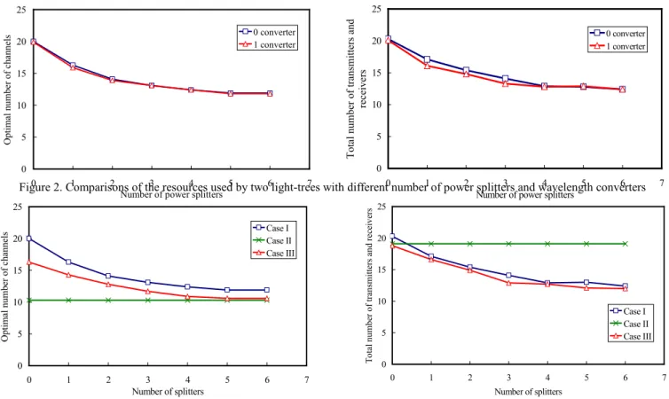
Fig. 2 is the result averaged over 10 cases. The sender and destinations of each light-tree in all cases are chosen randomly. The average number
Figure 2. Comparisons of the resources used by two light-trees with different number of power splitters and wavelength converters
Figure 3. Comparisons of the resources used by two multicast streams with different deployments
0 5 10 15 20 25 0 1 2 3 4 5 6 7
Number of power splitters
O pt im al numbe r of c ha nne ls 0 converter 1 converter 0 5 10 15 20 25 0 1 2 3 4 5 6 7
Number of power splitters
T ota l num be r of tra ns m itte rs a nd re ce ive rs 0 converter 1 converter 0 5 10 15 20 25 0 1 2 3 4 5 6 7 Number of splitters Op tim al n um ber o f ch an ne ls Case ICase II Case III 0 5 10 15 20 25 0 1 2 3 4 5 6 7 Number of splitters To tal n um be r o f tran sm itters an d receiv ers Case I Case II Case III
of destinations on a light-tree is set to 6. The number of wavelengths that a fiber supports is set to 4. The number of optical transmitters and receivers of each node are both set to 10 for the above three cases. Here the objective function is modified to find the minimal number of optical transmitters and receivers used by light-trees when the optimal number of wavelength channels is found. As expected, both the number of wavelength channels and the total number of optical transmitters and receivers are reduced when more power splitters and wavelength converters are used.
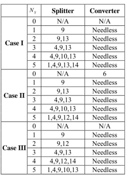
The second part of our results is to compare the three approaches to supporting multicast streams in section II-B. We consider the following three cases:
• Case I: two multicast streams are transmitted on two separate light-trees.
• Case II: two multicast streams are multicast in a logical network. All nodes are capable of electronic processing. Hence, the logical topology is the same as the physical topology. Light-trees are not supported in the physical network.
• Case III: multicast is supported in both logical and physical networks.
The data rate of each multicast stream is set as half of the maximal data rate that a wavelength channel can support. The results are averaged over 10 samples. The parameters are the same as in Fig. 2.
Fig. 3 shows the optimal number of wavelength channels and the total number of optical transmitters and receivers versus different number of power splitters in a network. Case II uses the least number of wavelength channels because we assume all nodes are capable of multicasting. In real networks, however, only part of the nodes in WDM networks is capable of electronic processing. Since multicast is achieved
over logical networks in case II, more optical transmitters and receivers are used. Compared to case I, case III uses less number of wavelength channels, optical transceivers and receivers because a light-tree can carry data from both streams. With a few power splitters, the number of wavelength channels used in case III is close to that in case II. However, case III requires far fewer optical transmitters and receivers. Since the cost of power splitters is less expensive than that of optical transmitters and receivers [6], case III
TABLE I.
NUMBER OF OPTICAL CHANNELS VERSUS DIFFERENT NUMBER OF POWER
SPLITTERS
Number of power splitters
0 1 2 3 4 5
Case I 24 18 16 15 14 13
Case II 23 18 16 15 14 13
Case III 23 18 16 15 14 13
TABLE II.
TOTAL NUMBER OF OPTICAL TRANSMITTERS AND RECEIVERS VERSUS
DIFFERENT NUMBER OF POWER SPLITTERS
Number of power splitters 0 1 2 3 4 5 All cases 22 18 16 14 14 14
TABLE III.
PLACEMENT OF POWER SPLITTERS AND WAVELENGTH CONVERTERS VERSUS
TOTAL NUMBER OF OPTICAL TRANSMITTERS AND RECEIVERS VERSUS
DIFFERENT NUMBER OF POWER SPLITTERS
S N Splitter Converter 0 N/A N/A 1 9 Needless 2 9,13 Needless 3 4,9,13 Needless 4 4,9,10,13 Needless Case I 5 1,4,9,13,14 Needless 0 N/A 6 1 9 Needless 2 9,13 Needless 3 4,9,13 Needless 4 4,9,10,13 Needless Case II 5 1,4,9,12,14 Needless 0 N/A N/A 1 9 Needless 2 9,12 Needless 3 4,9,13 Needless 4 4,9,12,14 Needless Case III 5 1,4,9,10,13 Needless
outperforms the other two cases.
五、結論
In this paper, we have presented an Mixed Integer Linear Programming (MILP) formulation to solve the optimal routing and wavelength assignment problem of light-trees with an end-to-end delay bound, and obtain the optimal placement of power splitters and wavelength converters in the network. The results show that networks with just a few power splitters and wavelength converters can efficiently carry multicast data. We have also extended the above formulation to design a light-tree based topology for multicast streams with an end-to-end delay bound, and obtain the optimal routing of multicast streams. We have demonstrated that this approach can use the network resources more efficiently, as compared to the approach in which each multicast stream is transmitted on a different light-tree, and the approach in which all streams are multicast in logical networks.
參考資料
[1] R. Ramaswami and K. N. Sivarajan, “Design of Logical Topologies for Wavelength-Routed Optical Networks,” IEEE J. Select. Areas Commun., vol. 14, no. 5, Jun. 1996, pp. 840-851.
[2] D. Banerjee and B. Mukherjee, “Wavelength-Routed Optical Networks: Linear Formulation, Resource Budgeting Tradeoffs, and Reconfiguration Study,” IEEE/ACM Trans. Networking, vol. 8, no. 5, Oct. 2000, pp. 198-607.
[3] R. M. Krishnaswamy, and K. N. Sivarajan, “Design of Logical Topologies: A Linear Formulation for Wavelength-Routed Optical Networks with No Wavelength Changers,” IEEE/ACM Trans. Networking, vol. 9, no. 2, Apr. 2001, pp. 186-198.
[4] M. Tornatore, G. Maier, and A. Pattavina, “WDM Network Optimization by ILP Based on Source Formulation,” IEEE INFOCOM’02.
[5] G. Sahin and M. Azizoglu, "Multicast Routing and Wavelength Assignment in Wide Area Networks", Proceedings of SPIE, vol. 3531, pp. 196-208, 1998.
[6] L. H. Sahasrabuddhe and B. Mukherjee, “Light-Trees: Optical Multicasting for Improved Performance in Wavelength-Routed Networks,” IEEE Commun. Mag., Feb. 1999, pp. 67-73.
[7] X. Zhang, J. Wei, and C. Qiao,” Constrained Multicast routing in WDM Networks with Sparse Light Splitting,” IEEE INFOCOM’00, pp. 1781-1790.
[8] Xiao-Hua Jia et al., “Optimization of Wavelength Assignment for QoS Multicast in WDM Networks,” IEEE Tran. Commun., vol. 49, no. 2, Feb. 2001, pp. 341-350.
[9] B. Chen and J. Wang, “Efficient Routing and Wavelength Assignment for Multicast in WDM Networks,” IEEE J. Select. Areas Commun, vol. 20, no. 1, Jan. 2002, pp. 97-109. [10] M. Gondran and M. Minoux, Graph and Algorithms, New
York: Wiley, 1984.
[11] Noronha Jr. and F. A. Tobagi, “Optimum Routing of Multicast Streams,” IEEE INFOCOM’94, pp. 865-873.
[12] M. Ali and J. S. Deogun., “Power-Efficient Design of Multicast Wavelength-Routed Networks,” IEEE J. Select. Areas Commun, vol. 18, no. 10, Oct. 2000, pp. 1852-1862. [13] M. Ali and J. Deogun “Allocation of Multicast Nodes in
Wavelength-Routed Networks,” IEEE ICC’01, vol. 2, pp.615-618.
[14] S. Yan , M. Ali, and J. Deogun, “Route Optimization of Multicast Sessions in Sparse Light-splitting Optical Networks,” IEEE GLOBECOM’01, vol. 4, pp. 2134-2138. [15] M. Mellia et al. “Optimal Design of Logical Topologies in
Wavelength-Routed Optical Networks with Multicast Traffic,” IEEE GLOBECOM’01, vol. 3, pp.1520-1525.
[16] S. Subramaniam et al., “All-Optical Networks with Sparse Wavelength Conversion,” IEEE/ACM Trans. Networking, vol. 4, no. 4 Aug. 1996.
[17] G. Xiao and Y. Leung, “Algorithms for Allocating Wavelength Converters in All-Optical Networks,” IEEE/ACM Trans. Networking, vol. 7, no. 4, Aug. 1999, pp. 545-557. [18] S. Subramaniam et al., “On Optimal Converter Placement in
Wavelength-Routed Networks,” IEEE/ACM Trans. Networking, vol. 7, no. 5, Oct. 1999, pp. 754-766.
[19] S. Jiang and T. E. Stern, “Regular Multicast Multihop Lightwave Networks,” IEEE INFOCOM’95, vol. 2, pp. 692-700.
[20] S. Jiang, T. E. Stern, and E. Bouillet, “Design of Multicast Multilayered Lightwave Network,” IEEE GLOBECOM’93, vol. 1, pp. 452-457.
[21] ILOG CPLEX Optimization Package. http://www.ilog.com/products/cplex/