rl‘
I ’
’I1
’I
1298 IEEE PHOTONICS TECHNOLOGY LETERS, VOL. 4, NO. 11, NOVEMBER 1992
CONCLUSIONS
The measured receiver performance in Fig. 2 is about
10 dB worse than the quantum limit. Of this, 3.7 dB are due to the mixing efficiency and 6.3 dB are due to the excess APD photodetector noise ( F = 2.6), nonoptimal two-wave mixing gain ((1
+
C2/rniX1+
& / c ) ~
=1.4), and thermal noise (TN = 0.7) at a BER of The
use of a different photorefractive material for which 2:
1, and a better APD-preamplifier combination so that
F = 2 would reduce this difference to 3 dB. Nevertheless, this extremely simple coherent optical homodyne receiver which required no accurate beam alignment or mode- matching optics and performed phase tracking automati- cally by virtue of the dynamic nature of the photorefrac- tively formed refractive index grating gave quite good performance, attaining a BER of at about 75 de- tected signal photons per bit.
REFERENCES
[l] G. Hammel de Montchenault, B. Loiseaux, and J. P. Huignard, “Two-wave mixing with time modulated signals in BiI2SiOzo the- ory and application to homodyne wave-front detection,” J. Appl. [2] F. Davidson, M. Krainak, and L. Boutsikaris, “Coherent optical detection through two-wave mixing in photorefractive materials,”
Opt. Lett., vol. 13, pp. 506-508, 1988.
[3] F. Davidson and L. Boutsikaris, “Homodyne detection using pho- torefractive materials as beamsplitters,” Opt. Eng., vol. 29, pp. [4] G. Picoli, P. Gravey, C. Ozkul, and V. Viuex, “Theory of two-wave mixing gain enhancement in photorefractive 1nP:Fe: a new mecha- nism of resonance,” J. Appl. Phys., vol. 66, pp. 3798-3813, 1989. [SI F. Davidson, C. Field, and X. Sun, “50 Mbps free-space direct
detection laser diode optical communication system with Q = 4 PPM signaling,” Free-Space Laser Commun. Technologies 11,
D. Begley and B. Seery, Eds. Proc. SPIE, vol. 1218, pp. 385-395, 1990.
[6] G. S. Mecherle, “Detection alternatives for pulse position modula- tion (PPM) optical communication,” in Opt. Technologies for Com- mun. Satellite Appl., in Proc. SPIE, vol. 616, pp. 105-116, 1986. Php., vol. 63, pp. 624-627, 1988.
369-377, 1990.
Synchronization of Electrical and Optical
Signals by Using an Optoelectronic Timing
Discriminator in
a
Phase-Lock Loop
Ci-Ling Pan and Hsiao-Hua Wu Abstract-A GaAs:Cr photoconductive switch is employed as
an optoelectronic timing discriminator or phase detector in the phase-lock loop. Timing information is derived from the tempo- rally sloped output of the switch, which is the cross-correlation function of the electrical signal and the photoconductive re- sponse induced by the laser pulse train. Optoelectronic synchro- nization of microwave signals up to 12 GHz in a laser-diode- based system has been demonstrated. The long-term relative timing jitter between the electrical and optical signals is esti- mated from the error signal in the PLL to be less than 500 fs. This technique can also be used to synchronize lasers.
INTRODUCTION
HASE coherence or timing synchronization between
P
exciting and probing signals is indispensable when one uses short laser pulses to perform a variety of time- resolved measurements, e.g., electrooptic sampling [l], [21,Manuscript received May 15, 1992; revised August 14, 1992. This work was supported in part by the National Science Council of the Republic of China under Grants NSC81-0417-E009-629 and 630.
The authors are with the Institute of Electro-Optical Engineering, National Chiao Tung University, Hsinchu, Taiwan 300, Republic of China.
IEEE Log Number 9204003.
photoconductive sampling [3], optical waveform sampling [4], and time-resolved spectroscopy [5]. In these experi- ments, the system under study is typically excited and probed by optical pulses derived from the same laser source to eliminate the effect of pulse timing fluctuations. Nevertheless, it is sometimes required to inject the system under test with an electronic signal or excite with one laser and probe with a different laser. In those cases, the degradation of the system temporal resolution caused by the relative timing jitter between the excitation sources and the probe laser could be a serious problem.
Previously, Elzinga et al. used two synthesizers operated in a master-slave (i.e., phase-locked) configuration to minimize relative drift between two synchronously pumped dye lasers [6]. For electrooptic sampling applications, Rodwell et al. [7] employed a stable radio-frequency syn- thesizer to phase lock a microwave frequency synthesizer via a common reference frequency and at the same time achieved subpicosecond timing stabilization of a pulse- compressed actively mode-locked Nd:Yag laser by active feedback techniques. With a passively mode-locked laser, e.g., the colliding-pulse mode-locked (CPM) ring dye laser, 10 MHz square wave signal obtained by dividing the 100
MHz output of a photodetector monitoring the laser pulse train can be used as the external reference to synchronize 1041-1135/92$03.00 0 1992 IEEE
PAN A N D WU: SYNCHRONIZATION OF ELECTRICAL AND OPTICAL SIGNALS 1299
the high-frequency synthesizer [8]. These systems are fairly complicated and require high quality synthesizers to achieve good stability. Dijaili et al. [91 developed a pulsed optical phase-lock loop to synchronize a gain-switched laser diode to a CPM ring dye laser. In this scheme, an optical second harmonic cross-correlator was utilized as the time delay discriminator or phase detector in a phase lock loop (PLL). The signal generator driving the laser diode in turn can be used to trigger other electrical signals with low relative timing jitter and high fan out. Quite recently, optical phase-locking of a free running microwave oscillator to the repetition frequency of a pulsed laser has been demonstrated by using electrooptic
[ 101 and photoconductive [ 111 harmonic mixing tech- niques, respectively. These techniques can be used with either actively or passively mode-locked lasers and poten- tially are capable of wafer level phase-locking of mi- crowave signal up to 100 GHz.
In this letter, we describe a new scheme for timing synchronization of optical with electrical/optical signals. A photoconductive switch is utilized in the PLL as an optoelectronic timing discriminator (OETD) to directly measure the change of the temporal position of the opti- cal probe pulses relative to the electrical waveform. Tim- ing synchronization without offset frequency can thus be realized.
EXPERIMENTAL TECHNIQUES
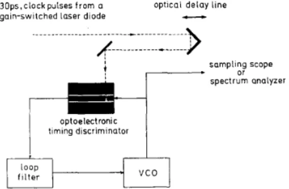
Fig. 1 shows a schematic diagram of our experimental setup. It contains three basic components: an OETD or phase detector, a loop filter, and a voltage-controlled oscillator (VCO). The light source is a gain-switched AlGaAs laser diode (Mitsubishi, model ML-4102, A = 790 nm) driven by a comb generator (HP33004) at f, = 500
MHz and generates 30 ps optical pulses. This provides the optical clock for the system. The OETD consists of a photoconductive switch with a straight 10-pm gap in a 50 R coplanar waveguide transmission line fabricated on the GaAs:Cr substrate. A microwave sweep oscillator (HP8350B) is employed as the VCO, of which the gain constant has been verified experimentally to be 6 MHz/V. When the switch is excited by optical pulses from the laser diode at an average power of 0.75 mW and biased at 2 V, it generates 95 ps electrical pulses with 4 mV peak voltage as observed on a sampling oscilloscope (Tektronix 7854 w/S-4 sampling head). As an OETD, the photoconductive switch would be biased by an ac electrical signal. The temporally sloped output of the switch, which is the cross correlation between the electrical signal and the photo- conductive response induced by laser pulses, is used as the error signal. It is then filtered and negatively fed back to synchronize the VCO in the PLL. We assume that the photoconductive response is gaussian in shape with full width at half maximum (FWHM) of t R , and the electrical signal is a sinusoid with angular frequency of uRF. The peak amplitude of the output of the OETD then decays as the angular frequency increases according to e x p ( - [ o R , t , , / ( 4 ~ ) ] 2 } . If one of the signals is much
3 0 p s . c l o c k p u k e s from a optical d e l a y line gain-switched l a s e r diode cc s a m p l i n g s c o p e
i
or s p e c t r u m analyzer optoelectronic timing discriminatorFig. 1. Schematic diagram of the experimental setup.
shorter in duration than the other, the cross-correlation function reduces to the shape of the broader waveform. When the phase-locking condition is realized, the OETD output voltage V, is proportional to the product of the relative delay between the two signals and the OETD gain, K d . The latter quantity depends on the duration and amplitude of the electrical signal, laser pulse width and energy, as well as the photoconductive gain. With a 500 MHz sinusoidal electrical input signal at 10 dBm, the OETD used in our experiment exhibited a gain, k , = 60
pV/ps into 2 K R load.
RESULTS AND DISCUSSIONS
We have locked the VCO to the gain-switched laser diode at the frequencies that are exactly equal to the fundamental or harmonics of the repetition frequency of the optical pulse train, i.e., fRF = nf,, where n is an
integer. In Fig. 2, the waveforms of an optoelectronically synchronized 12-GHz signal (lower trace) and the 500 MHz optical clock (upper trace) as observed on the sam- pling oscilloscope (triggered by either trace) are shown. The spectrum of the same 12-GHz signal is shown in Fig. 3. We have also synchronized 100-ps electric pulses from a comb generator. The spectral purity of the harmonic spectrum of the syncrhonized pulses are similar to that of the electrical signal shown in Fig. 3. At an offset fre- quency of 1 kHz, the residue sideband noises (1 Hz bandwidth) are -85, -70, and -55 dBc with the VCO at 500 MHz, 2 GHz, and 12 GHz, respectively. It is found that the sideband noise of the locked signal increases at the higher harmonics of the clock frequency. This may be attributed to the degradation of the OETD output ampli- tude as the frequency of electrical signal increases. For the experiment with the VCO at 500 MHz and 2 GHz, it
is also found that the sideband noise to carrier power ratio of the locked signal increases as the square of the harmonic number n of the VCO frequency. This reveals that the noise sideband predominantly originates from phase noise. Limited by available equipments, we are not able to measure the noise of the locked signal at harmon- ics of 12 GHz. Residue amplitude noise contributed by the VCO ( I 50 dBc, 100 kHz bandwidth), is expected to
I ' I I( 1300 TEK17054 WO 5OmVldiv 200pSldiv W l 200mVIdiv 200pSldiv WO
i
Fig. 2. Waveform of optoelectronically synchronized sinusoidal electri- cal signal at 12 GHz (lower trace, vertical scale: 50 mV/div., horizontal scale: 200 ps/div.) and the 500 MHz optical clock signal (upper trace: vertical scale: 200 mV/div., horizontal scale: 200 ps/div.).
IEEE PHOTONICS TECHNOLOGY LElTERS, VOL. 4, NO. 11, NOVEMBER 1992
LEVEL FREOLENCY ;FAN 3JV REF OOBM CEN 1 2 0 0 0 026 73GHZ 500d2 DBM
MAR - L SoBM MKR 1 2 0 0 0 0 2 6 73GHZ , c I _L-_ _ _ _
--.A
-89 l O D B l 2 0 0 8 5L-18 INT lOOHZ RECLUTION DISNAAY ATTENUATION RANGE 05C JANOWIOM VERT:CAL RF FREO REFFig. 3. Power spectrum of the optoelectronically synchronized 12 GHz electrical signal. (resolution bandwidth: 100 Hz, span: 500 Hz/div., vertical scale: 10 dB/div.).
be negligible. The upper limit for the operation frequency is set by the photoconductive cross correlation response. The relative timing jitter between the optical clock pulses and the phase-locked signal is estimated from the peak- to-peak fluctuation amplitude of the error signal, and the gain constants of the OETD and the VCO. As
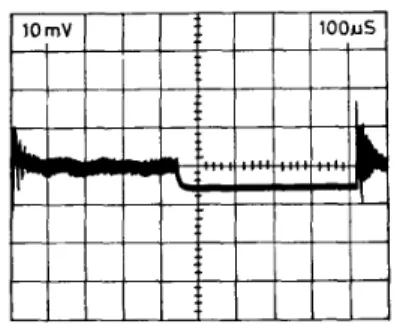
discussed by Dijaili et al. [9], this approximation is valid as long as the frequencies of all the timing fluctuations of the laser fall within the loop bandwidth. For our gain- switched laser diode, short-noise-limited spectrum mea- surement at the 20th harmonics of the detected pulses shows that the frequency spread of the timing fluctuations occupy a band less than 1 kHz, measured at - 48 dB from the peak. Our PLL has a bandwidth of = 25 kHz. By chopping the microwave signal at 1 kHz and monitoring the error voltage, we find that the PLL tracks in = 100 ps and I 5 mV in the short-term ( = 1 ms). This is shown in Fig. 4. The long-term drift of A%.'.-. is less than 10 mV over a period of 2 h. Using the gain constants of the OETD and the VCO, we estimate that the relative timing jitter between the optical clock and the VCO is
Fig. 4. Error voltage (relative timing jitter) at the output of the OETD (vertical scale: 10 mV/div., horizontal scale: 100 ps/div.). The mi- crowave signal was chopped at l IrHz.
less than 500 fs. Further improvements are expected by optimizing the parameters of the loop filter and replacing the present VCO by a signal generator with smaller gain constant. The amplitude noise present in the pulsed laser may also cause fluctuations in the error signal and con- tribute to the relative timing jitter between VCO output signal and the system clock. This problem can be solved by normalizing the output signal of the OETD with the output signal of a detector monitoring the laser power. Alternatively, one can choose to operate two correlators at the quiescent points of the inverse slopes respectively and taking their difference as the OETD output. Mono- lithic integration of the OETD and the rest of the PLL is also relatively straightforward.
It is interesting to compare the present technique with previous approaches. In our previous work [ l l ] and that of Li et al. [lo], the output of the photoconductive or elec- trooptic harmonic mixer at the intermediate frequency, Af = nf, - f R F , was compared at a phase detector with
that of the reference frequency. In the present technique, the OETD itself is the phase detector. Additional refer- ence signal is not needed. Furthermore, the synchronized signals are related by nf, = f R F , with Af = 0. It is worth
noting that the present technique can be thought of as the reverse of the optoelectronic microwave PLL demon- strated by Lau [12]. In his work, a RF generator was used to phase lock a self-pulsating laser diode. Dijaili et al. [9] used a photomutiplier tube (PMT) for detection. In com- parison, the OETD employed by us exhibits higher lock- ing bandwidth ( = 10 times higher). Because the OETD is ac biased, the dark current is also much smaller. The bandwidth of the OETD is limited by that of the photo- conductor. Operation in the millimeter wave frequency range should be straightforward as photoconductors with bandwidth as high as several hundred gigahertz has re- cently been reported [13].
CONCLUSIONS
We have presented a new method for synchronizing electrical and optical signals without offset by employing an optoelectronic timing discriminator as a phase detector in a PLL. Microwave signals up to 12 GHz have been
1301
IEEE PHOTONICS TECHNOLOGY LETTERS, VOL. 4, NO. 11, NOVEMBER 1992
tive timing jitter between the optical and electrical signals is estimated to be less than 500 fs. The output signal of optoelectronically phase-locked VCO can be used to drive other lasers or devices for further applications with low relative timing jitter. Other applications of this method include timing stabilization and synchronization of active and passive mode-locked lasers.
ACKNOWLEDGMENT
Helpful discussions with Dr. C.-S. Chang are gratefully acknowledged.
REFERENCES
[l] J. A. Valdmanis, G. A. Mourou, and C. W. Gabel, “Picosecond electro-optic sampling systems,” Appl. Phys. Len., vol. 41, pp.
[2] B. H. Kolner and D. M. Bloom, “Electrooptic sampling in GaAs integrated circuits,” IEEE J. Quantum Electron., vol. QE-22, pp.
[3] H. L. A. Hung, P. Polak-Dingels, K. J. Webb, T. Smith, H. C. Huang, and C. H. Lee, “Millimeter-wave monolithic integrated circuit characterization by a picosecond optoelectronic technique,”
IEEE Trans. Micrownue Theory Tech., vol. MTT-37, pp. 1223-1230,
1990.
[4] J. M. Wiesenfeld, R. S. Tucker, P. M. Downey, and J. E. Bowers, “Optical correlation measurement of switching transients in high- speed semiconductor lasers,” Electron. Lett., vol. 22, pp. 396-397,
1986.
[5] F. J. Shah, T. C. Damen, and B. Deveaud, “Femtosecond lumines- 211-212,1982.
79-93, 1986.
cence spectroscopy: Investigation of semiconductors and semicon- ductor microstructures,” in Ultrafast Phenomena VI, T. Yajima,
K. Yoshihara, C. B. Hams, and S. Shionoya, Eds. Berlin Heidel- berg: Springer-Verlag, 1988, pp. 288-293.
P. A. Elizinga, R. J. Kneisler, F. E. Lytle, Y. Jiang, G. B. King, and N. M. Laurendeau, “Pump/probe method for fast analysis of visible spectral signatures utilizing asynchronous optical sampling,” M. J. W. Rodwell, D. M. Bloom, and K. W. Weingarten, “Subpico- second laser timing stabilization,” ZEEE J. Quantum Electron., vol. J. A. Valdmanis, “Electro-optic measurement techniques for pi- cosecond materials, devices, and integrated circuits,” in Semicon-
ductors and Semimetah, vol. 28, R. B. Marcus, Ed. New York Academic, 1990, pp. 135-219.
S. P. Dijaili, J. S. Smith, and A. Dienes, “Timing synchronization of a passively mode-locked dye laser using a pulsed optical phase lock loop,” Appl. Phys. Lett., vol. 55, pp. 418-420, 1989.
M. G. Li, E. A. Chauchard, C. H. Lee, and H.-L. A. Hung, “Intermixing optical and microwave signals in GaAs microstrip circuits for phase-locking applications,” IEEE Trans. Microwave Theory Tech., vol. MlT-38, pp. 1924-1931, 1990.
H.-H. Wu, C.-S. Chang, and C.-L. Pan, “Optoelectronic phase- locking of microwave signals up to 18 GHz by a laser-diode-based GaAs:Cr photoconductive harmonic mixer,” ZEEE Microwave
Guided Wave Lett., vol. 2, pp. 11-13, 1992.
K. Y. Lau, “Short-pulse and high-frequency signal generation in semiconductor lasers,” J. Lightwave Technof., vol. 7, pp. 400-419, 1989.
Y. Chen, S. Williamson, T. Brock, F. W. Smith, and A. R. Calawa, “375-GHz-bandwidth photoconductive detector,” Appl. Phys. Lett.,
Appl. Opt., vol. 26, pp. 4303-4307, 1987.
QE-25, pp. 817-827, 1989.
vol. 59, pp. 1984-1986, 1991.
Reduction
of Fiber Four-Wave Mixing
Influence Using Frequency Modulation in
Multichannel IM/DD Transmission
Kyo Inoue
Abstract-A novel technique is proposed to reduce fiber-wave mixing (FWM) influence on system pedormance in multichan- nel IM / DD transmissions. The optical frequency is modulated such that the spectrum of the beat component between the selected signal and FWM lights is spread and the affection of the beat component is reduced by filtering in the baseband stage. A numerical simulation shows that the FWM influence is reduced to less than -6 dB over conventional systems using this technique.
Manuscript received July 9, 1992; revised August 14, 1992. The author is with N’IT Transmission Systems Laboratories, Kana- IEEE Log Number 9204004.
gawa 238-03, Japan.
IBER nonlinearity [l] has been the focus in optical