A Cascade Multilevel STATCOM for Wind Generation Systems
S. D. Gamini Jayasinghe
School of Electrical and Electronic Engineering
Nanyang Technogical University 50 Nanyang Avenue,
Singapore 639798 shan0034@ntu.edu.sg
D. M. Vilathgamuwa
Senior Member, IEEE School of Electrical and Electronic
Engineering
Nanyang Technogical University 50 Nanyang Avenue,
Singapore 639798 emahinda@ntu.edu.sg
U. K. Madawala
Senior Member, IEEE Department of Electrical & Computer
Engineering,
University of Auckland, Auckland, New Zealand
u.madawala@auckland.ac.nz
Abstract--This paper presents a novel STATCOM
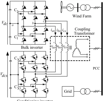
configuration for voltage quality improvement in wind power generation systems. The proposed STATCOM is formed by cascading two 3-level inverters, ‘bulk inverter’ and
‘conditioning inverter’, through a coupling transformer. Both inverters are powered by dc-link capacitors and they are charged by a small amount of active power drawn from the grid. To minimize switching losses, the high power bulk inverter operates at low frequency while low power high frequency conditioning inverter is used to suppress harmonic content produced by the bulk inverter output. With only 24 switches this topology can synthesize a nine level inverter, if the dc-link voltage ratio is maintained at 3:1. Modulation and control techniques have been developed to meet this requirement.
Reactive power of the STATCOM is controlled to mitigate voltage sags or swells caused by sudden wind changes.
Simulation and experimental results are presented to verify the efficacy of the proposed modulation and control techniques used in the STATCOM.
Index Terms--Cascade Multilevel converter, STATCOM, Neutral point potential balancing.
I. I
NTRODUCTIONThe Static Synchronous Compensator (STATCOM) is a Flexible AC Transmission System (FACTS) device for reactive power compensation and voltage regulation that has played an important role in power industry since 1980. Fast dynamic response of STATCOMs makes them suitable for mitigating potential short term voltage fluctuations that last for few hundreds of milliseconds particularly in wind generation systems. Furthermore, it has been recognized that STATCOMs have advantages over the conventional Static Var Compensators (SVC) as they generate less harmonic currents and require a much smaller reactor. Conventional STATCOMs use two-level Voltage Source Converters (VSC) for power processing. As compared to the two-level VSC configuration, multilevel configuration is more suitable for STATCOM realization since it provides higher ac-side voltage levels and improved waveforms with reduced harmonic distortion. Multilevel converter topologies such as diode-clamped converter, flying-capacitor converter and cascading converter have been made as STATCOM power processor so far. The converter used in this paper is a combination of diode clamped and cascading converters and is configured by cascading two units of diode-clamped three
level inverters. This configuration offers superior performance and has been used in high power motor drive applications [1] [2].
Bulk inverter
Conditioning inverter
PCC
Coupling Transformer C
1C
2C
X1C
X2i
asi
bsi
csv
as+v
bs+v
cs+- - -
Vdc
Vdcx
Wind Farm
Grid
a b
c o
Fig. 1. Schematic of the proposed STATCOM (Vdc : Vdcx = 3:1)
Fig. 1 shows the schematic of the proposed STATCOM in which the two inverters, “Bulk Inverter” and
“Conditioning Inverter”’ are connected at the ends of a coupling transformer secondary winding. The dc-link of each inverter consists of two capacitors. They are charged by active power drawn from the grid. The bulk inverter operates at a low frequency producing square wave output with required amplitude and phase while high frequency low power conditioning inverter is used to make the output waveform smooth and closer to sinusoidal in shape. To obtain the maximal distention for this cascade-3/3 inverter, conditioning inverter dc-link voltage should be maintained at one third of the bulk inverter dc-link voltage [2]. Under such a condition, these two inverters effectively produce a nine- level inverter with only 24 switches. The most important feature of this converter is that, as the high power bulk inverter operates at low frequency it can be constructed using
PEDS2009
devices like GTOs, ETOs or IGCTs to reduce switching losses. On the other hand, the conditioning inverter, which acts to compensate low order harmonics produced by the bulk inverter, can be constructed using more common devices like IGBTs.
This paper describes control and modulation methods for the cascaded multilevel converter, dc-link capacitor voltage regulation and in particular STATCOM controller. The STATCOM controller, proposed to mitigate potential voltage sags and swells in a Permanent Magnet Synchronous Generator (PMSG) based wind energy conversion system, is described in Part II. A detailed analysis of the inverter controller is given in Part III. Permanent Magnet Synchronous Generator model and the related controller is described in Part IV. Simulation and experiment results are given in Part V and VI to show the efficacy of the proposed STATCOM.
II. STATCOM C
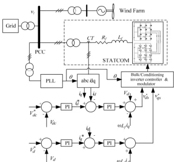
ONTROLLERFig. 2 shows the controller block diagram of the STATCOM that controls the active and reactive power transfer between the grid and the STATCOM. The measured grid voltage V
d, in synchronous reference frame, is compared with the reference V
*dand the error signal produced is then fed into a PI controller that generates a current reference i
*qfor the inner current controller loop. The STATCOM’s ac side currents are measured and transferred to the synchronous reference frame in the form of direct and quadrature components. The direct component is related to the real power exchange while quadrature component is related to the reactive power exchange. Therefore, the bulk inverter dc-link voltage, V
dccan be maintained by controlling the direct component of the STATCOM’s current. To regulate the grid voltage, the quadrature component of the STATCOM’s current is controlled [3]-[4]. The current controller outputs, v
*dsand v
*qsare the reference voltages for the inverter. With these references, amplitude A
mand the angle α
mof the STATCOM output voltage can be calculated using (1) and (2). Consequently, the STATCOM inverter controller generates output voltages with required amplitude and phase.
The instantaneous angle θ, of the phase voltage vector, is obtained through a Phase Locked Loop (PLL).
*2
*2
1
qs ds dc
m
v v
A = V + (1) θ
α ⎟⎟ ⎠ +
⎜⎜ ⎞
⎝
= tan
−1⎛
**ds ds
m
v
v (2)
π
dccos β
f
v = V (3)
⎟⎟ ⎠
⎜⎜ ⎞
⎝
= ⎛ ∗
dc m
V π A
β cos
1(4)
Fig. 2. Schematic control diagram of the STATCOM connected in a wind generator system
III. PQ C
OMPENSATIONB
ASEDC
ONDITIONINGI
NVERTERC
ONTROLLERFig. 3 shows the bulk inverter voltage variation at point
‘a’ with respect to point ‘o’ i.e. V
ao. It has three levels called Positive, Zero and Negative. Angle β is called the firing angle and it determines the amplitude of the fundamental component, v
f ,according to (3). As the conditioning inverter only mitigates the harmonics produced by the bulk inverter, it does not change the amplitude of the fundamental output.
Therefore, the fundamental amplitude of the bulk inverter output voltage governs the amplitude of the STATCOM output voltage. In other words reference amplitude A
m, generated by the STATCOM controller, should be equals to v
f. To meet that condition firing angle β is calculated according to (4). Therefore, by controlling the firing angle β, of the bulk inverter output, the STATCOM output voltage can be controlled [2]. After calculating the firing angle, next step is to find suitable bulk vectors. For that, space vector diagram of the cascade multilevel inverter has to be studied.
Fig. 3. Bulk inverter line to neutral point voltage
The cascade inverter space vector switching diagram, for the dc- link voltage ratio 3:1 (V
dc= 3V
dcx), is shown in Fig. 4.
Darker dots in the diagram show the switching states of the bulk inverter and are known as “bulk vectors”. They can be categorized into five groups. 1) Large vectors 200, 220, 020, 022, 002 and 202, 2) Medium vectors 210, 120, 021, 012, 102 and 201, 3) Negative small vectors 100, 110, 010 011,
PEDS2009
001, and 101, 4) Positive small vectors 211, 221, 121, 122, 112 and 212 and 5) Zero vectors 000, 111 and 222.
Therefore, altogether there are 27 bulk vectors marked by darker dots. Each darker dot is the origin of another smaller hexagonal pattern which represents the switching states of the conditioning inverter. They are the vectors of the conditioning inverter and are simply known as “conditioning vectors”. These small hexagons also have the same vector pattern as the bulk inverter. As a result of this, 27X27 different vectors can be identified for this cascade-3/3 inverter. But some of them overlap as shown in Fig. 4. The darker dots are marked with corresponding switching states.
The switching state ‘2’ means both upper switches are turned on. Similarly, the switching state ‘1’ means middle two switches are turned on and the switching state ‘0’ means the lower two switches are turned on.
Fig. 4. Cascade inverter space vector diagram for Vdc : Vdcx = 3:1
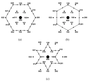
A given reference voltage vector can be synthesized by combining a bulk vector and three conditioning vectors. As mentioned in the introduction, the bulk inverter produces square wave outputs by switching from one bulk vector to another slowly. For 0
0< β <30
0, only large and medium bulk vectors are used to synthesize the bulk inverter voltages as shown in Fig. 5(a). Sub hexagonal vector patterns are omitted in these diagrams as the focus at this point is only on bulk vectors. For β =30
0, only medium bulk vectors are used as in Fig. 5(b). For 30
0< β <60
0, both medium and small bulk vectors are used and Fig. 5(c) shows the alternative use of small and medium bulk vectors under this condition [2].
[
dss]
s ds s qs s
qs
i v i
v
P =
23+ (5)
[
qss]
s ds s ds s
qs
i v i
v
Q =
23− (6)
⎟ ⎟
⎠
⎞
⎜ ⎜
⎝
⎛ +
− +
=
2 2*
*
*
3 2
s ds s qs
s ds x s qs s x
qsx
i i
i Q i
v P (7)
⎟ ⎟
⎠
⎞
⎜ ⎜
⎝
⎛ +
− −
=
2 2*
*
*
3 2
s ds s qs
s qs x s ds s x
dsx
i i
i Q i
v P (8)
(a) (b)
(c)
Fig. 5. Bulk vector selection for (a)
0
0< β <30
0, (b)β =30
0, (c)30
0< β
<60
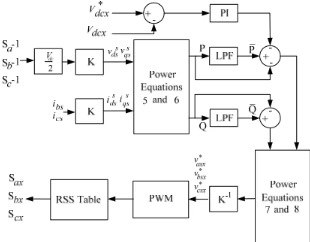
0Fig. 6 shows the block diagram of the conditioning inverter controller where v
qssand v
dssare calculated based on the bulk inverter switching states S
a, S
band S
c. The d-q synchronous reference frame currents i
qssand i
dssare calculated using measured STATCOM phase currents i
bsand i
cs. The instantaneous active power (P) and reactive power (Q) delivered by the bulk inverter are calculated using (5) and (6). The DC values of P and Q are obtained by passing instantaneous vales through low pass filters as shown in Fig.
6. The difference between the filtered and instantaneous values of P and Q represents the compensation power which should be supplied by the conditioning inverter [2]. They are denoted by P
x*and Q
x*respectively. Those active and reactive power compensation values are then used to calculate required voltages of the conditioning inverter using inverse power solutions (7) and (8). Negative signs appear in (7) and (8) as currents in the conditioning inverter are opposite to the load current directions. The reference voltages in (7) and (8) are then passed through a PWM block to obtain switching states of the conditioning inverter [5]. A redundant state selection algorithm is used to balance the conditioning inverter capacitor voltages. A PI controller is used to regulate the active power drawn from the bulk inverter in a way such that conditioning inverter dc-link voltage is maintained at 1/3 of the bulk inverter dc-link voltage for the nine level operation. Bulk inverter dc-link voltage regulation is carried out by the STATCOM controller shown in Fig.2. There the PI controller, which generates the current reference i
d*, is used to maintain the bulk inverter dc-link voltage.
PEDS2009
Fig.6. Conditioning inverter controller block diagram
IV. PMSG C
ONTROLLERPermanent Magnet Synchronous Generators (PMSG) have been gaining acceptance in direct coupled low- speed wind generation applications as they are highly efficient and relatively small in diameter [6]. Therefore, to test the ability of the proposed STATCOM to mitigate potential voltage variations, caused by sudden wind changes, a PMSG based wind energy conversion system is used. Fig. 7 shows the controller block diagram of the PMSG. For maximum power point tracking, the wind turbine model in the controller generates a reference speed for the PMSG using the measured wind speed and the optimum Tip Speed Ratio of the turbine. The difference of the actual speed and its reference is then fed into a speed regulator. As the speed is controlled by regulating the electrical torque, the currents of the grid interfacing inverter are controlled in a manner that the desired torque, which indirectly tracks the optimal speed of the PMSG.
Fig. 7. PMSG controller block diagram
V. S
IMULATIONR
ESULTS0.2 0.3 0.4 0.5 0.6 0.7 0.8 0.9 1
4 6 8 10
Time (S)
Wind Speed (m/s)
(a)
(b)
0.2 0.3 0.4 0.5 0.6 0.7 0.8 0.9 1
0 200 400 600 800
Time (S)
Current (A)
iq*
iq
id
(c)
0.2 0.3 0.4 0.5 0.6 0.7 0.8 0.9 1
-500 0 500
Time (S)
Current (A)
(d)
0.2 0.3 0.4 0.5 0.6 0.7 0.8 0.9 1
-5000 0 5000
Time (S)
Voltage (V)
(e)
0.2 0.3 0.4 0.5 0.6 0.7 0.8 0.9 1
-5 0 5
x 104
Time (S)
Voltage (V)
(f)
0.3 0.31 0.32 0.33 0.34 0.35 0.36 0.37 0.38 0.39
-2000 0 2000
Time (S)
Voltage (V)
(g)
0.2 0.3 0.4 0.5 0.6 0.7 0.8 0.9 1
1800 2000 2200
Time (S)
Voltage (V)
(h)
0.2 0.3 0.4 0.5 0.6 0.7 0.8 0.9 1
600 650 700 750
Time (S)
Voltage (V)
(i)
0.2 0.3 0.4 0.5 0.6 0.7 0.8 0.9 1
3 3.5 4 4.5x 10⁴
Time (S)
Voltage (V)
PEDS2009
Fig. 8. Dynamic behavior of the system for step changes in wind speed, (a) Wind speed, (b) PCC voltage restoration in synchronous reference frame, (c) STATCOM active and reactive current components, (d) STATCOM current - phase ‘a’, (e) STATCOM output voltage - phase ‘a’, (f) voltage at PCC, (g)
an exaggerated view of the STATCOM output voltage, (h) Bulk inverter capacitor voltages, (i) Conditioning inverter capacitor voltages
Fig. 8 shows the dynamic behavior of the STATCOM for a step change in wind speed. As shown in Fig. 8(a), at t = 300 ms, wind speed is changed from 9.3 ms
-1to 6.3 ms
-1, and again changed to 8.1 ms
-1at t = 700ms. These sudden variations make the voltage at PCC to deviate from its set value. The STATCOM detects those deviations and injects appropriate amount of reactive power to bring the voltage to the set value. Fig. 8(b) shows the results of voltage restoration attempts of the STATCOM. Without the STATCOM being connected, magnitude and duration of voltage variations would well exceed acceptable levels.
Therefore, it can be seen that fast acting STATCOMs can effectively mitigate voltage fluctuations caused by sudden wind changes in wind generation systems. Fig. 8(c) shows the variation of the reactive current reference i
q*and the actual reactive current i
qof the STATCOM. The reactive current i
qfollows the reference with a small delay. A small active current, i
d, is drawn from the grid to compensate switching losses in the STATCOM and to maintain the bulk inverter dc-link voltage. Fig. 8(d) shows variation of the STATCOM current of phase ‘a’. STATCOM output voltage and the voltage at PCC are shown in Fig. 8(e) and Fig. 8(f) respectively. A magnified view of the STATCOM output voltage variation from t = 300ms to t = 390ms is given in Fig.
8(g). With the 9-level operation of the VSC, harmonic distortion of the STATCOM output voltage is greatly reduced. The bulk inverter and conditioning inverter dc- link voltage regulation is shown in Fig. 8(h) and Fig. 8(i) respectively. Note that the conditioning inverter voltage is maintained at one third of the bulk inverter dc link voltage for 9-level operation. The results show a good performance of the proposed PMSG, STATCOM and inverter control systems.
Table I. System parameters of the simulated system
VI. E
XPERIMENTALR
ESULTS(a)
(b)
(c)
(d)
(e)
Fundamental frequency f = 50Hz
STATCOM Interfacing Resistance R
f= .05Ω STATCOM Interfacing Inductance L
f= .5mH
PCC voltage v
l= 69kV
Coupling transformer turns ratio 4.16 : 69
DC-Link voltage V
dc= 4000V
DC-Link capacitors C
1,C
2,C
X1,C
X2C = 2200μF
STATCOM power rating 5MVA
Conditioning inverter switching
frequency 5kHz
5ms/div
Voltage 7V/div Voltage 7V/div
5ms/div
Current 1A/div Am 2 units/div
5ms/div
5ms/div
PEDS2009
(f)
(g)
(h)
(i)
(j)
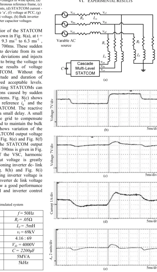
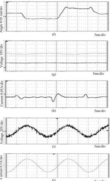
Fig. 9. Experimental results, (a) experiment setup, (b) PCC voltage without STATCOM, (c) PCC voltage with STATCOM, (d) injected reactive current,
(e) amplitude Am (f) power angle, (g) bulk and conditioning inverter dc-link voltages, (h) active current, (i) STATCOM output voltage vas, (j) STATCOM
output current
Table II. System parameters of the experimental setup
The laboratory prototype of the cascade multilevel STATCOM is set up as in Fig. 9(a). A programmable AC
source is used to synthesize the PMSG based wind energy conversion system. Three step changes are introduced on its output voltage v
nto observe the dynamic response of the STACOM as in Fig. 9(b). The system of Fig. 9(a) is initially at steady state and when a change of the PCC voltage v
lis sensed an appropriate amount of reactive current is injected to restore it to the nominal value as shown in Fig. 9(d). The result of this restoration attempt is shown in Fig. 9(c). The variation of modulation index A
mand power angle α
mis shown in Fig. 9(e) and Fig. 9(f) respectively. At the beginning of this process, voltage V
dis at its nominal value.
Therefore, reactive power injection is not required. Once a change in voltage V
dis sensed the controller starts to inject reactive power to bring V
dback to the nominal value. DC- link capacitor voltage variations are shown in Fig. 9(g). A small active current, i
d, is drawn from the grid as shown in Fig.9(h) to maintain capacitor voltages and replenish power loss due to switching and resistive components of the coupling transformer. An elaborated view of the inverter output voltage and current is shown in Fig. 9(i) and Fig. 9(j) respectively. It can be seen from these results that the cascade multilevel STATCOM controller perform exceedingly well in transient and steady state conditions
VII. C
ONCLUSIONSA novel STATCOM, as a solution for potential voltage quality problems related to wind power generation systems, is presented. The related modulation and control techniques are explained in detail. The proposed STATCOM shows good dynamic responses for voltage variations by restoring the PCC voltage to its desired value. The simulation and experimental results show good performance of the dc-link voltage regulation and capacitor voltage balancing techniques. These results indicate that the proposed cascade multilevel STATCOM can improve the quality of the output of wind generation systems with reduced harmonics and switching losses.
VIII. R
EFERENCES[1] K.A. Corzine, et.al. “Control of cascaded multilevel inverters”, IEEE Trans. on Power Electron., Vol.19, No. 3, pp. 732-738, 2004.
[2] S. Lu, K.A. Corzine, “Advanced Control and Analysis of Cascaded Multilevel Converters Based on P-Q Compensation”, IEEE Trans. on Power Electron., vol.22, no. 4, pp. 1242-1252, 2007.
[3] Wanki Min; Joonki Min; Jaeho Choi, “Control of STATCOM using cascade multilevel inverter for high power application” Proc. of the International Conference on Power Electronics and Drive Systems, 1999 PEDS99, Volume 2, Issue , 1999, pp. 871 – 876, Vol. 2.
[4] C. Schauder and H. Mehta, “Vector analysis and control of advanced static VAR compensators” Proc. Inst. Elect. Eng. C, Vol.140, No. 4, pp.
299-306, Jul. 1993.
[5] K. A. Corzine and J. R. Baker, “Multilevel voltage-source duty-cycle modulation: Analysis and implementation,” IEEE Trans. Ind. Electron., Vol. 49, No. 5, pp. 1009–1016, Oct. 2002.
[6] D. M. Vilathgamuwa, Wang Xiaoyu, C. J. Gajanayake, “Z-source converter based grid-interface for variable-speed permanent magnet wind turbine generators,” Proc. Power Electronics Specialists Conference, 2008, PESC 2008.
Fundamental frequency f = 50Hz
STATCOM Interfacing Resistance R
s= 2Ω STATCOM Interfacing Inductance L
s= 3mH
Line resistance R
n= 4Ω
Line Inductance L
n= 34mH
Load resistance R
l= 55Ω
Load Inductance L
n= 110mH
DC-Link voltage V
dc= 60V
DC-Link capacitors C
1,C
2,C
X1,C
X2C = 2200μF Nominal value of V
d35V
Angle 0.05 rad/div Voltage 10V/div Current 0.05A/div Voltage 20V/div Current 0.5A/div
5ms/div
5ms/div
5ms/div
5ms/div
5ms/div