A Study of Applying Systematic Methods on the Computer-Aided Automobile Shape Constructions and Simulations
Shih-Wen Hsiao* Chi-Hung Lo Ya-Chuan Ko
Department of Industrial Design, National Cheng Kung University, Tainan, Taiwan 70101, ROC
* Corresponding author: E-mail: swhsiao@mail.ncku.edu.tw
Abstract
Automobiles are an essential mean of transportation in our daily life. The automobile industry, involving engineering design and aesthetics, has always been known as the industrial locomotive.
Based on the trend of automatic design, this research took off from the perspective of industrial design, and combined the scope of industrial design, Computer Aided Design (CAD) and Computational Fluid Dynamics, proposing a computer aided automobile modeling design program that would help designers to develop and modify their designs.
In the design case, a car body surface model that can be modified locally was first built. Then aerodynamics was used to simulate and analyze the flow structure of the surface so that the designers could modify the surface model accordingly, which reduced the number of wind tunnel tests required compared to the traditional design. The design program proposed in this research can reduce the cost of the general design process, increase work efficiency, thus reaching the aim of automated design.
Key Words: CAD, body surface modeling, automobile flow analysis
I. Introduction
With changes of social economy and life mode, automobile industry, always known as the leader of industries, has officially been one of the key indicators for high-efficiency life. As for process of vehicle design, taking automobile for example, traditional automobile style developing procedure has to spend a large amount of manpower and time on correction of sketch model and make and modification of clay model, which, compared to the design concept of real time (Tovey, 1989), has been an obstacle that causes discontinuity of design thoughts in designers.
To probe into vehicle design, designers are at the interface between consumers and products, who, on one hand, find out consumers' needs by analysis on market demand and translate them into design information; on the other hand, have to apply their designs in the functions of vehicles to meet consumers' needs. On the interface of processing vehicle information, while using automatic design tools, designers still have to flexibly link their thoughts in intuition and intention of correction (Tovey, 1992).On the other hand, in the process to define and transform consumers' needs, there is a problem of how to measure and quantize the uncertainty as so to further expand and transparentize the design process (Jones, 1992).
On both market demand and engineering analysis, automobile is the most discussed vehicle
type, especially on engineering analysis which is usually led by engineers and focuses on CAD
framework of body and construction of performance. However, apart from aesthetic functions and
symbolizing functions (Tuttlw, 1991), some virtual functions such as safety and power are more
important in design of automobile style. In recent years, with rapid development of computers,
software developed for simulative flow field (TR219, 1992) enables numeric computation mode for hydrodynamics (Cheret, 1987; Rawnsiey & Glynn, 1987; Shaw, ) to increasingly replace the traditional wind tunnel experiments, reducing test times and shortening period of research and development. While as far as designers concerned, how to consider and integrate the automatic shape-building and analyzing software in future engineering applications is the principal approach to design of automobile style.
As Hsiao (1994) has built and completed a database for enquiry of basic automobile styles in order to design automobile styles which meet consumers' demand, this research tried to establish a set of systematic CAD program for design of automobile style, offered to designers to apply dim idea to automatic facilities, quickly building the curve of designed concept body, trying to importing style curvature entropy to evaluate the complexity of the style of head and trail, and working out better and safer model by aerodynamic simulation. Through the analysis on flow field structure around automobile, a set of quick and accurate simulating method is to be established to reduce test times and wind tunnel experiment times so as to achieve automatization and high- efficiency.
II. Theoretical Background 2.1 Styling entropy
Claude Shannon (1948) proposed a revolutionary mathematic field---information theory.
Shannon stated a theory on quantization of general information and description of message, especially architecture of probability describing message. Some researchers have applied information theory in different fields such as communication, astronomy and crystallography. Oddo (1992) developed a kind of segmentation arithmetic to acquire airplane picture to build a range in sphere entropy for complexity of different shape of satellite image. Cesar and Costa (1997) proposed to measure shape with multidimensional scaling and to develop class nerve morphology.
King and Rossignac (1999) proposed a directly associated triangle grid data set. Toussaint (1991) advised to resolve 2D polygon and measure and calculate complexity of shape based on it, and also proposed a replacement of polygon edge in turn to generate spiral direction. Chazelle and Incerpi (1984) suggested curve times as a complexity computation mode; Young, Walker and Bowie (1974) used curving power to measure shape to describe figure characteristic of creature objects. Vliet and Verbeek (1993) expanded the definition of curving power to 3D data set. These key methods have enlightened the method of applying information theory for description of shape. Pal N.R. and Pal S.K. (1989) advised to define grey entropy following Oddo.
In research on complexity of form, Page, D.L. et. al. (2003) applied Shannon's Entropy to measure complexity of 2D graph and 3D structure. While in research on visual cognition of forms or artificial vision, thermal function "entropy" is often introduced into complexity of forms, and is called "curvature entropy" of figure. Complexity of shape is judged by the value of curvature. The larger value of curvature entropy is, the more complex the graph gets; on the contrary, the smaller value of dissimilar curvature is, the smaller value of curvature entropy becomes, and the simpler the graph gets.
The formula for curvature entropy is:
ni
i
i
p
p H
1
log
2(1) Where, H=complexity.
i=the number of occurrence of styling figure on line curvature.
Pi=possibility of occurrence of the ith kind of figure on line curvature.
2.2 Analysis on flow field around automobile
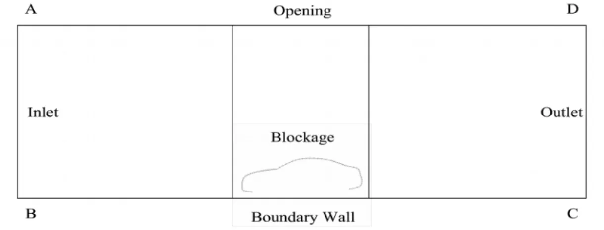
Set boundary condition and environment variables for preparation work; set its free boundary condition, relative pressure, automobile speed, wind speed, fluid property and other boundary condition. The boundary is shown as Figure 1: Inlet, outlet, block, boundary wall. The height is 5 times of the vehicle height; the flow field in front of the vehicle is 5 times of the body; the flow field behind the vehicle is 6 times of the body. Fluid property: 1. Air density: 1.189 kg/m
3; 2.
Coefficient of dynamic viscosity: 1.544 ×
105 m2 sec. Standard Value of Experiment Coefficient in k−ε Mode of Turbulent Flow, as shown in Table 1.
Figure 1: Sketch of Boundary Condition
Pressure coefficient:
22 1
V Cp p
(2)
Coefficient of frictional resistance:
22 1
V C
r w
(3)
Coefficient of wind resistance:
22 1
V A
F C F
t f p
d
(4)
Where:
C : p
Pressure coefficient
Cr:
Coefficient of frictional resistance
C : d
Coefficient of wind resistance
p:
Relative pressure difference
:Air density
V:
Traveling speed of vehicle
w:
Shearing strength on the wall
F : p
Profile drag
F : f
Pressure resistance
A : t
Area of the section in the forward direction
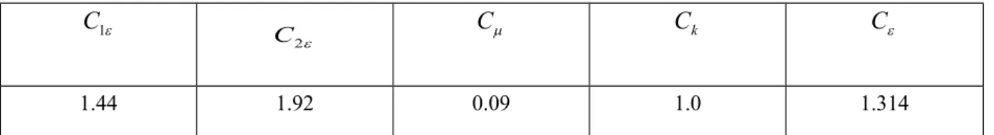
Table 4: Standard Value of Experiment Coefficient in k−ε Mode of Turbulent Flow
1
C
C2
C
C
kC
1.44 1.92 0.09 1.0 1.314
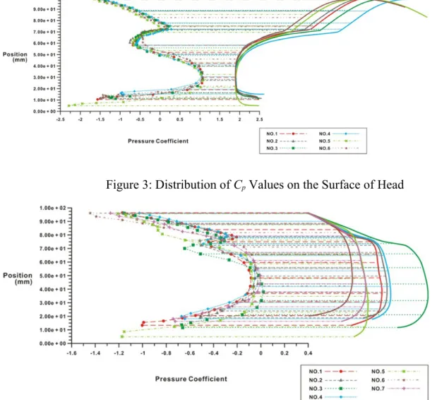
Input 2D grid data of body into the chart applying Fluent to display simulative analyses, including value curve chart, pressure distribution chart, values, and chart of airflow structure on the surface of body, etc., which are used as reference for evaluation of automobile styling and performance and for study on wind drag around vehicle and wind pressure value for shape correction, and as the standard for evaluation of vehicle shape.
2.3 Theory of turbulent flow model
Turbulent flow enables fluid media to exchange momentum, power and thickness, which
causes many fluctuations that are of small scale and high frequency, so high requirement of
computers is needed if direct simulation is applied in actual engineering computation. Therefore,
while turbulent flow is being simulated, controlling equation should be processed first to filter out
turbulent flows of small scale and high frequency. But the modified equation may contain some
changes unknown to us, which have to be identified by turbulent flow model by using known
changes. This research chooses standard mode in K−ε turbulent flow model while simulating
turbulent flow as calculating turbulent flow.
III. Research method and procedure
3.1 Definition of vehicle shape and characteristics of styling
The first step for research was to collect side elevations of vehicles with various styles manufactured in recent years, mainly from 2004 to 2008. To obtain a diversity of vehicle styles and to avoid too much of similar styles, 95 sample pictures were collected in all, covering various styles of mass-produced cars and concept cars.
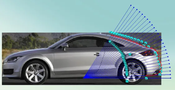
This research divided the side profile of a car into three parts: head contour, roof contour, and tail contour. The head contour is defined as from the lower edge of bumper to the front edge of windscreen; the roof contour is from the front edge of windscreen to the upper edge of rear windscreen; and the tail contour is from the upper edge of rear windscreen to the lower edge of rear bumper. To define these contours, software SolidWorks was used to make radiation lines from the central point of the chassis and obtain the intersection points of where the radiation lines cross the contour. In addition, due to different complexity of lines at different parts, a different number of radiation lines were made for different parts. 32 lines were made for the head, 16 lines for the roof and 24 lines for the tail, as shown in Figure 2.
Figure 2: Car contour points
The automobile pictures were converted, according to their proper proportions, into data of figure points in the software and store in the contour database built. The data were then loaded by parts into statistical analysis software to perform cluster analysis. The clusters were divided with Ward or Euclidean distance to obtain the results based on the characteristics of the cars’ profile.
According to the results of the cluster division, the head contour can be divided into six groups; and the tail contour can be divided into seven groups. A representative sample of each group was also obtained.
3.2 Styling integration
In this research, fluid simulation was used to pick out the characteristic curve for the group
with the most samples in the roof and tail characteristic groups, and confirm the characteristic curve
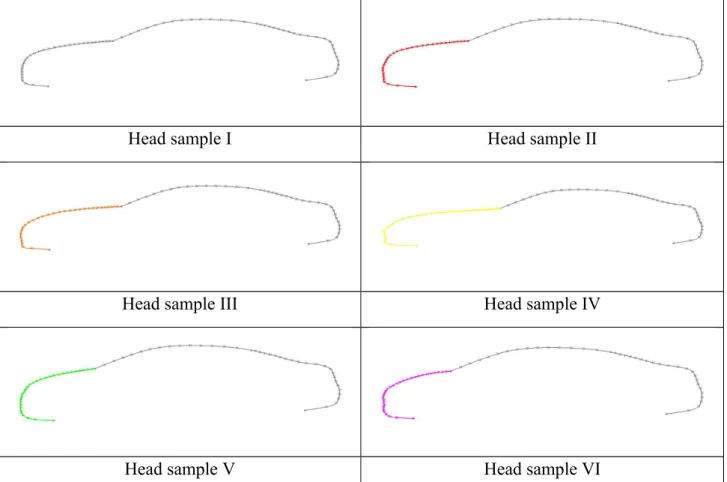
parameters to match them respectively with the six representative samples of the head contour group. Six different new car styles with different head contour were obtained, as shown in Table 2.
Table 2: Six new styles with different head contour
Head sample I Head sample II
Head sample III Head sample IV
Head sample V Head sample VI
In addition, fluid simulation was also used to pick out the characteristic curve for the group with the most samples in head and roof characteristic groups, and confirm the characteristic curve parameters to match them respectively with the seven representative samples of the tail contour group. Seven different new styles with different tail contour were obtained, as shown in Table 3.
Table 3: Six new styles with different tail contour
Trail sample I Trail sample II
Trail sample III Trail sample IV
Trail sample V Trail sample VI
Trail sample VII
3.3 Calculate styling curvature entropy
First, the six samples of head contour acquired in cluster analysis were introduced into the formula of curvature entropy to calculate the values of all head curvature entropies (shown as in Table 4), and then the seven sample of tail contour acquired in cluster analysis were also introduced into the formula to calculate the values of all tail curvature entropies (shown as in Table 5).
Table 4:
Values of Six Head Sample Curvature EntropiesHead sample 1
Head sample 2
Head sample 3
Head sample 4
Head sample 5
Head sample 6 Curvature
entropy
5.220 5.345 5.294 5.502 5.699 5.445Table 5:
Values of Seven Tail Sample Curvature EntropiesTrail sample 1
Trail sample 2
Trail sample 3
Trail sample 4
Trail sample 5
Trail sample 6
Trail sample 7 Curvature
entropy
5.706 5.429 5.213 5.420 5.768 5.410 5.5323.4 Procedure for simulation of flow field values
The whole analysis area for the 2D car model lies on the plane of x=1, and number of division points is 42 × 87 in y and x directions, respectively; the relative error value for change of residual value of accuracy of numerical convergence is set as 600.
The boundary conditions are:
1. Free boundary condition
0
n