Chapter 2
Modeling and static analysis
First, a mathematical formulation derivied for each translating and rotating degree of freedom in a EPFHM is based on the characteristic of static mechanism, the design fundamental, stiffness estimation, and the functional experiment of a EPFHM. It leads to easily decompose the force and bending moment of the designated EPFHM into force components in X,Y, Z-axis and bending moment components in X,Y,Z-axis. Eventually, the stiffness of each axis is derived from the following methodology.
2.1 General equation of displacement relative to force in translation and rotation
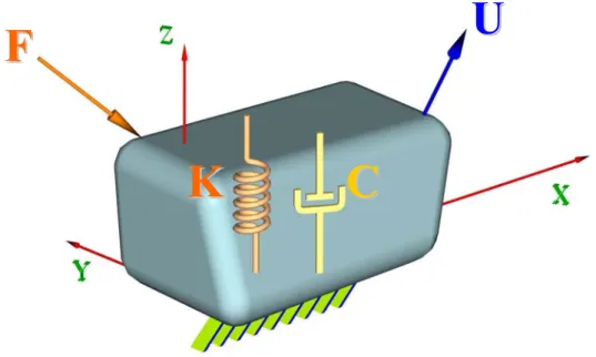
Six degrees of freedom in translation/rotation are respectively defined as X, Y, Z, A, B and C-axis. The characteristics of the design fixture need to be defined as shown in Fig. 4 for illustrating the behavior of X,Y and Z axes translation.
Fig. 4 Schematic diagram of X-Y-Z translation
The force definitions of piezoelectric EPFHM for finding translation and rotation stiffness are derived as follows.
K λ U
F= (1) where,
[
Fx Fy Fz]
=
F is the force of X,Y and Z axes.
[
∆x ∆y ∆z]
=
U is the displacement of X,Y and Z axes.
⎥⎥
⎥
⎦
⎤
⎢⎢
⎢
⎣
⎡
=
z y x
λ λ λ
0 0
0 0
0 0
λ , and λx,λy,λz are respectively calibrated
functions of material property in X,Y and Z axes. It proves that the EPFHM material has probable non-isotropy property by the experiment. If the λ is constant proved by the experiment, the translation axial material property is regarded as linear inclination.
F F
K K C C
U U
⎥⎥
⎥
⎦
⎤
⎢⎢
⎢
⎣
⎡
=
z y x
K K K
0 0
0 0
0 0
K , and Kx , Ky , Kz are the ratio of force
z y
x F F
F , , and its corresponding displacement ∆x,∆y,∆z in X,Y and Z axes respectively.
Kx,Ky,Kz are evaluated by FEA. Eq.(1) is defined as
Trans
S U
F= (2)
Trans
S is defined as a characteristic matrix of a EPFHM translation to help matrix operation and coordinate transformation.
⎥⎥
⎥
⎦
⎤
⎢⎢
⎢
⎣
⎡
=
z z y y x x
Trans
K K
K
λ λ
λ
0 0
0 0
0 0
S
And, the displacement of characteristic matrix is derived from the following formula.
S 1
F
U= −Trans (3) The relationship of bending moments, stiffness and angular displacement in A, B, and C axes, is shown as below.
R R
R F θχ K
r
M= × = (4) Among,
[
Mx My Mz]
=
M , Mx,My,Mz are respectively bending moment in A,B and C axes.
[
Rx Ry Rz]
R = F F F
F , which is the force applied to the proper position of a EPFHM results in bending moment components of A, B and C axes.
⎥⎥
⎥
⎦
⎤
⎢⎢
⎢
⎣
⎡
=
Rz Ry Rx
χ χ χ
0 0
0 0
0 0
χ , χRx,χRy,χRz are respectively calibrated
functions of material property in X, Y and Z rotational axes. It also proves that the EPFHM material has probable non-isotropy property by the experiment. If the χ is constant proved by the experiment, the rotation axial material property is regarded as linear inclination.
[
∆θx ∆θy ∆θz]
=
θ is the angular displacement vector of X,Y and Z rotational axes.
⎥⎥
⎥
⎦
⎤
⎢⎢
⎢
⎣
⎡
=
Rz Ry Rx
R
K K K
0 0
0 0
0 0
K , andKRx,KRy,KRz are the ratio of bending
moment Mx,My,Mz to its corresponding angular displacement
z y
x θ θ
θ ∆ ∆
∆ , , in X,Y and Z axis respectively.
According to the design method, KRx,KRy,KRzare evaluated by FEA. Eq.(4) is defined as
Rot
R θS
F = (5)
SRot is defined as a characteristic rotation matrix of a EPFHM to help matrix operation and coordinate transformation.
⎥⎥
⎥
⎦
⎤
⎢⎢
⎢
⎣
⎡
=
Rz Rz Rz Ry Ry Ry Rx Rx Rx
Rot
r K r
K r
K
χ χ
χ
0 0
0 0
0 0
S
And, the angular displacement vector is derived as given by S 1
F
θ= R −Rot (6) In fact, FRx,FRy,FRz results in the translation effect of a fixture and which is
S 1
F
U= R Tran− (7) Combining Eq.(3) with Eq. (7) results in
S 1
F F
U=( + R) Trans− (8)
Therefore, the displacement from FR is compensated by F.
2.2 General equation of displacement relative to voltage in translation and rotation
The force of PZT is expressed as l
K
FPiezo =λPiezo Piezo∆ (9) And, λPiezo is defined as Eq.(1).
The relationship of displacement and voltage is )
(V f l=
∆ (10) so, the relationship of PZT force and voltage is
) (V f K
FPiezo =λPiezo Piezo (11) The stiffness value of varied PZT is
) / ( 4000
~
4 N m
KPeizo ≈ µ (12) The displacement of a EPFHM is occurred due to KPiezo >>KFixture. Correspondingly, the translation and rotation effects are caused by the input displacement of a PZT.
The contact with a PZT and EPFHM causes varied friction instead of backlash error of a mechanism. The forces F and FR of Eq.(7)(8) cause the displacement without the consideration of energy loss. According to the mentioned derivation, adding the PZT
[
Px Py Pz]
P = F F F
F , is the PZT force, which leads to the
translation of X, Y, and Z axes.
[
PRx PRy PRz]
PR = F F F
F , is the PZT force, which leads to the
bending moment of X, Y, and Z axes.
From Eq.(8), S 1
η F η F
U=( P + PR R) Trans− (13) Among,
⎥⎥
⎥
⎦
⎤
⎢⎢
⎢
⎣
⎡
=
z y x
η η η
0 0
0 0
0 0
η ,
⎥⎥
⎥
⎦
⎤
⎢⎢
⎢
⎣
⎡
=
Rz Ry Rx
R
η η η
0 0
0 0
0 0 η
About the contact problem by the FEA simulation, it reveals that the output displacement will just linearly increase along the input force; however, it will not correspondingly reflect to the same result of experiment. Therefore, η and ηR must be the transfer functions between EPFHM force F,FR and PZT force FP,FPR.
And,
P
P QK
F =
PR R
PR Q K
F = (14) Among,
[
fx(Vx) fy(Vy) fz(Vz)]
=
Q is the displacement function vector,
which is occurred by the translation of three PZTs with different voltage in X,Y, and Z axes.
[
Rx( Rx) Ry( Ry) Rz( Rz)]
R = f V f V f V
Q is also the function vector and
the displacement, which is occurred by the bending moment of a PZT with the voltage in X,Y, and Z axes.
⎥⎥
⎥
⎦
⎤
⎢⎢
⎢
⎣
⎡
=
z Piezo y
Piezo x
Piezo
P
K K
K
0 0
0 0
0 0
K Among, KPiezox , KPiezoy and KPiezoz
are respectively the stiffness of three PZTs which create translations in X,Y, and Z axes.
⎥⎥
⎥
⎦
⎤
⎢⎢
⎢
⎣
⎡
=
Rz Piezo Ry
Piezo Rx
Piezo
PR
K K
K
0 0
0 0
0 0
K Among, KPiezoRx , KPiezoRy and
Rz Piezo
K are respectively the stiffness of three PZTs which create bending moments in X,Y, and Z axes.
From Eq.(13), it reveals S 1
K η Q K η Q
U=( P + R R PR) Trans− (15) Accordingly, Eq.(6) is represented as
S 1
η F
θ= PR R −Rot (16) From Eq.(14),
S 1
K η Q
θ= R R PR −Rot (17)