22. K.L. Wong and C.H. Chang, WLAN chip antenna mountable above the system ground plane of a mobile device, IEEE Trans Antennas Propag 53 (2005), 3496 –3499.
23. K.L. Wong and C.H. Chang, Surface-mountable EMC monopole chip antenna for WLAN operation, IEEE Trans Antennas Propag 54 (2006), 1100 –1104.
24. Ansoft Corporation HFSS. Available at http://www.ansoft.com/prod-ucts/hf/hfss/.
© 2008 Wiley Periodicals, Inc.
DESIGN OF DUAL-BAND BANDPASS
FILTER USING DIVERSE
QUARTER-WAVELENGTH RESONATORS FOR
GPS/WLAN APPLICATIONS
Hung-Wei Wu,1Yan-Kuin Su,1Min-Hang Weng,2and Ru-Yuan Yang3
1Advanced Optoelectronic Technology Center, Institute of
Microelectronics, Department of Electrical Engineering, National Cheng Kung University, Taiwan
2National Nano Device Laboratories, Taiwan
3Institute of Material Engineering, National Pingtung University of
Science and Technology, Taiwan; Corresponding author: q1893106@mail.ncku.edu.tw
Received 28 January 2008
ABSTRACT: The novel compact dual-band bandpass filter (BPF) by using diverse quarter-wavelength (/4) resonators for global position system (GPS)/wireless local area network (WLAN) applications is pro-posed for the first time. The use of two interdigital-like/4 resonators of the proposed BPF effectively provides the responses for GPS/WLAN at 1.575/5.7 GHz by properly arranging the/4 SIRs. Full-wave simulator IE3D is used to design the proposed BPF. Good agreement with re-sponses of electromagnetic (EM) simulation and measurement is com-pared. © 2008 Wiley Periodicals, Inc. Microwave Opt Technol Lett 50: 2694 –2696, 2008; Published online in Wiley InterScience (www. interscience.wiley.com). DOI 10.1002/mop.23716
Key words: stepped impedance resonators (SIRs); GPS; WLAN; dual-band; bandpass filter
1. INTRODUCTION
In recent years, the development of multi-service mobile wireless communication system, such as combination of global position system (GPS) and wireless local area network (WLAN), global system for mobile communications (GSM) and GPS or GSM and WLAN, has become attractive for the commercial products. For example, the commercial product of N-series cellphone produced by Nokia provides the dual-service for GPS and GSM. Therefore, development of dual-band bandpass filter (BPF) is needed for the multi-service system.
Dual-band BPFs have been gaining a wide attention in recent years [1–7]. Several types of dual-band BPFs, such as the cascaded connection of bandpass and bandstop filters [1], coupled stepped impedance resonators (SIRs), [2– 4] and combination of two or more individual resonators [5–7]. However, most of the reported dual-band BPFs only show the dual passband performance in single-service system, especially in WLAN with IEEE 802.11 a/b standard. There is still a challenge to the designers is to simulta-neously achieve the compact size and low insertion loss when designing a dual-band BPF for the multi-service communication system. Quarter-wavelength (/4) SIRs are known to only exhibit higher order resonant modes at the odd harmonics [8] and to have
reduced resonator size. Typical configuration of interdigital BPF uses /4 uniform impedance resonators (UIRs). However, such BPF requires via holes to be the ground of the resonator and has the spurious responses appeared at about odd times of the desired fundamental passband [9].
In this letter, we propose novel dual-band BPF using diverse /4 resonators for GPS (1.575 GHz)/WLAN (5.7 GHz) applica-tion. The BPF is constructed from two-stepped impedance reso-nators (SIRs) and two coupling enhanced lines, as shown in Figure 1. Each resonator has an electric length within 90° at the center frequency f0and is short-circuited at one end and open-circuited at the other end. The proposed BPF simultaneously achieves the compact size, low loss, and good dual-band performance for GPS/WLAN. The theory and guidelines for designing the/4 SIRs are clearly presented in next section. The dual-band BPF is de-signed, fabricated, and measured. A good agreement between the electromagnetic (EM) simulated result and measured resulted is obtained.
2. CIRCUIT DESIGN
2.1. Design of the Quarter Wavelength SIRs
The structure of a/4 microstrip SIR is shown in Figure 2(a). The SIR is constructed by two sections with both different character-istic impedance and physical length. The impedance ratio (K) is defined as K ⫽ Z2/Z1, which is an important designed parameter to tune the properties of SIR. The input impedance Zi can be derived as:
Zi⫽ jZ2
Z1tan1⫹ Z2tan2 Z2⫺ Z1tan1tan2
(1)
Let Yi ⫽ 1/Zi ⫽ 0, the parallel resonant modes of SIR can be obtained as
tan1tan2⫽ K ⫽ Z2/Z1 (2) To obtain more design freedoms to control the resonant modes of the SIR, two sections can have different physical length. The length ratio of SIR is defined as ␣ ⫽ 2/(1⫹ 2) ⫽2/t[8]. Therefore, various K and ␣ value are to determine the higher resonant mode of the/4 SIR. The commercial RO 3003 substrate with a dielectric constantr⫽ 3, a thickness h ⫽ 0.508 mm, and a loss tangent tan␦ ⫽ 0.0013 is used in this study. Figure 2(b) shows the normalized ratio of the resonant frequency of the higher order mode to the resonant frequency of the fundamental mode for the/4 SIR. Since the /4 SIR only resonates at odd mode over
Figure 1 Configuration of the proposed dual-band BPF using diverse coupled/4 resonators
frequency spectrum, it is enough to separate the higher order mode and the fundamental mode widely to satisfy the required frequency ratio of 3.6 (⫽ 5.7/1.575) for GPS/WLAN application. Several combinations of K and␣ value can reach the requirement. 2.2. Design of BPF With Dual-Mode GPS/WLAN
The original theory and design flow for conventional interdigital BPF with tapped I/O line can be found in [9]. To meet the 1.575/5.7-GHz specification, both the Resonators 1 and 2 use/4 SIRs as shown in Figure 1. The resonant modes of the SIR have been determined according to the above-mentioned design guide. To simultaneously meet the requirements of the GPS and IEEE 802.11a with 5 GHz U-NII at upper band [10], the bandwidth for f01 ⫽ 1.575 GHz and f02 ⫽ 5.7 GHz are 60 and 200 MHz, respectively. The position of the tapped I/O lines with 50-⍀-lines is well designed by choosing the optimum external quality factor (Qe) [11].
Qe⫽ f0
␦f3⫺dB (3)
where f0 and ␦f3-dB express the center frequency and the 3-dB bandwidth of the passband, respectively. By bending the /4 resonators as shown in Figure 1, the BPF would have more compact size. In this study, we choose K⫽ 0.6 and␣ ⫽ 0.4 of SIR for achieving 1.575/5.7 GHz, which is marked as solid symbol
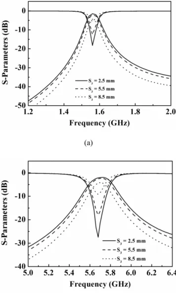
observed from Figure 2(b). Therefore, S1⫽ 0.1 mm, S2⫽ 1.5 mm, L1⫽ 16.6 mm, L2⫽ 12.2 mm, L3⫽ 12.9 mm, L4⫽ 15.6 mm, W1 ⫽ 2.4 mm, W2 ⫽ 1.8 mm, W3 ⫽ 0.8 mm, t ⫽ 2.3 mm are determined. Figure 3 shows the simulated frequency response of the dual-band BPF under different coupling spacing S3. When decreasing S3from 8.5 to 2.4 mm, it is clearly observed that the return losses ( S11) at the two passbands increase and the insertion losses ( S21) at two passbands also decrease due to the reduced intercoupling degree. Therefore, the coupling spacing S3is set as 2.4 mm. The simulation was carried out using IE3D[12].
3. RESULTS
Photograph of the fabricated dual-band BPF is shown in Figure 4(a). The size of the proposed BPF is around 25⫻ 14 mm2, which is approximately equal to 0.19 g ⫻ 0.11 g (g is the guide wavelength at f01). The BPF can be fabricated on the high permit-tivity ceramic substrate for further miniaturizing the circuit size. The measured frequency responses are characterized in an HP
Figure 2 (a) Structure and (b) normalized ratios of the resonant fre-quency of higher order mode to the resonant frefre-quency of fundamental mode for/4 SIR as function of K ⫽ 0.6, 0.8, 1, 1.6, and 1.8
Figure 3 Simulated frequency response of the BPF under different coupling spacing S3operating at (a) 1.575 GHz and (b) 5.7 GHz. (Since
K⫽ 0.6 and␣ ⫽ 0.4 are used, S1⫽ 0.1, S2⫽ 1.5, L1⫽ 16.6, L2⫽ 12.2,
L3⫽ 12.9, L4⫽ 15.6, W1⫽ 2.4, W2⫽ 1.8, W3⫽ 0.8, t ⫽ 2.3 are
determined and held in the simulation. All dimensional units are mm)
8510C network analyzer. The frequency responses of the EM simulation and measurement are shown in Figure 4(b). The mea-sured results of the BPF have S11 of 19 dB, S21 of 0.8 dB, and 3-dB fractional bandwidth (FBW) of 0.04 at 1.575 GHz and S11 of 27 dB, S21 of 1 dB, and FBW of 0.04 at 5.7 GHz. The measured frequency responses of the passband are closely matched the simulated results, thus verifying the theoretical prediction of the passband.
4. CONCLUSION
The compact dual-band BPF using diverse coupled/4 resonators has been presented for GPS (1.575 GHz)/WLAN (5.7 GHz) ap-plication. Detailed design procedure which has been described. By adjusting the impedance ratio and physical length of the SIRs, multiple resonant modes can be created and are suitably arranged for achieving dual-band performance with widely frequency range. Overall size of the BPF is around 0.19 g ⫻ 0.11 g. Good agreement with responses of electromagnetic simulation and mea-surement is compared.
REFERENCES
1. L.C. Tsai and C.W. Huse, Dual-band bandpass filters using equal-length coupled-serial-shunted lines and Z-transform techniques, IEEE Trans Microwave Theory Tech 52 (2004), 1111–1117.
2. J.T. Kuo, T.H. Yeh, and C.C. Yeh, Design of microstrip bandpass filter with a dual-passband response, IEEE Trans Microwave Theory Tech 53 (2005), 1331–1337.
3. S. Sun and L. Zhu, Compact dual-band microstrip bandpass filter
without external feeds, IEEE Microwave Wireless Compon Lett 15 (2005), 644 – 646.
4. M.H. Weng, H.W. Wu, and Y.K. Su, Compact and low loss dual-band bandpass filter using pseudo-interdigital stepped impedance resonators for WLANs, IEEE Microwave Wireless Compon Lett 17 (2007), 187–189.
5. M.H. Weng, C.Y. Huang, H.W. Wu, K. Shu, and Y.K. Su, Compact dual-band bandpass filter with enhanced feed coupling structures, Microwave Opt Technol Lett 49 (2007), 171–173.
6. J.X. Chen, T.Y. Yum, J.L. Li, and Q. Xue, Dual-mode dual-band bandpass filter using stacked-loop structure, IEEE Microwave Wire-less Compon Lett 16 (2006), 502–504.
7. C.F. Chen, T.Y. Huang, and R.B. Wu, Design of dual- and triple-passband filters using alternately cascaded multiband resonators, IEEE Trans Microwave Theory Tech 54 (2006), 3550 –3558.
8. S.C. Lin, P.H. Deng, Y.S. Li, C.H. Wang, and C.H. Chen, Wide-stopband microstrip bandpass filters using dissimilar quarter-wave-length stepped-impedance resonators, IEEE Trans Microwave Theory Tech 54 (2006), 1011–1018.
9. S. Caspi and J. Adelman, Design of combline and interdigital filters with tapped-line input, IEEE Trans Microwave Theory Tech 36 (1988), 759 –763.
10. IEEE 802.11a standard white paper, VOCAL Technologies, Ltd. pp. 18.
11. J.S. Hong and M.J. Lancaster, Microstrip filters for RF/microwave applications, Wiley, New York, 2001.
12. IE3D Simulator, Zeland Software, Inc., 2002.
© 2008 Wiley Periodicals, Inc.
DESIGN CONCEPT OF A MOBILE
HANDSET ANTENNA TO MITIGATE
USER’S HAND EFFECT
Sung-Joo Kim,1Ki-Hyun Kong,2Myun-Joo Park,1 Young-Seek Chung,1and Byungje Lee1
1Department of Wireless Communications Engineering, Kwangwoon
University, 447–1 Wolgye-Dong, Nowon-Gu, Seoul 139 –701, Korea; Corresponding author: bj lee@kw.ac.kr
2Electronic Component Development Team, LS Cable Ltd., 555
Hogye-Dong, Dongan-Gu, Anyang-Si, Gyeonggi-Do 431– 831, Korea
Received 29 January 2008
ABSTRACT: A meandered loop antenna with the modified ground plane in conjunction with the balanced structure is proposed to mitigate the degradation of antenna performance when the handset is directly held by the user’s hand. The antenna efficiency for a dual frequency band (AMPS and PCS) is studied under the influence of the user’s hand. © 2008 Wiley Periodicals, Inc. Microwave Opt Technol Lett 50: 2696 –2698, 2008; Published online in Wiley InterScience (www. interscience.wiley.com). DOI 10.1002/mop.23715
Key words: internal antenna; hand effect; mobile handset; modified ground plane
1. INTRODUCTION
The handsets for mobile communication systems are practically operated in the vicinity of a human body. Especially, the user’s hand is one of the parts that most frequently touch the mobile handsets even more often than the user’s head. When they are directly held by the user’s hand, some degradation on the imped-ance and radiation characteristics of the antenna due to variation of current distribution on the ground plane has been observed. To solve this problem, several studies of antenna performance under the influence of the user’s hand have been presented by using
Figure 4 (a) Photograph and (b) simulated and measured frequency responses of the fabricated dual-band BPF. S1⫽ 0.1, S2⫽ 1.5, S3⫽ 2.4,
L1⫽ 16.6, L2⫽ 12.2, L3⫽ 12.9, L4⫽ 15.6, W1⫽ 2.4, W2⫽ 1.8, W3⫽
0.8, t⫽ 2.3. All are in mm