Common Structural Rules for
Bulk Carriers and Oil Tankers
01 JAN 201 7
Foreword
These Rules enter into force on 1st July 2017 and supersede the following Rules:
• Common Structural Rules for Bulk Carriers and Oil Tankers, January 2015
These Common Structural Rules consist of two parts. Part One provides requirements common to both Double Hull Oil Tankers and Bulk Carriers and Part Two provides additional requirements applied to either Double Hull Oil Tankers or Bulk Carriers.
Summary of changes from the 01 JAN 201 5 Rules
Amendment Type / No. Adoption Date Rule Version Date Effective Date 1 Corrigenda 1 20 JAN 2016 01 JAN 2015 01 JAN 2015 2 Urgent Rule Change Notice 1 09 DEC 2016 01 JAN 2015 01 JUL 2017
Note: Full revision history for Common Structural Rules is available on IACS website, including all previous RCNs and associated TBs.
Guideline of RCN Label
1. RCN (Rule Change Notice) label is used to identify the rule change made since last rule version with the format of “RCN {Number} to {Rule Version Date}”, e.g. RCN 1 to 01 JAN 2015.
2. For corrigenda update, the same format will be followed, e.g. CORR 1 to 01 JAN 2015.
3. Modification and addition of rule texts:
RCN label is inserted at the end of modified contents.
4. Modification and addition of titles, figures and tables:
RCN label is inserted at the end of modified contents.
5. Deletion of rule texts and titles:
Replace contents by the word “DELETED”.
RCN label is inserted at the end of the word “DELETED”.
6. Deletion of Table:
Replace contents of Table by the word “DELETED” (only shown first row).
RCN label is inserted at the second row of Table.
7. Deletion of Figure:
Replace Figure by a generic graphic marked “DELETED”.
RCN label is inserted under the generic graphic.
Disclaimer
Copyright in these Common Structural Rules is owned by each IACS Member as at 1st July 2012.
Copyright © IACS 1st July 2012.
The IACS members, their affiliates and subsidiaries and their respective officers, employees or agents (on behalf of whom this disclaimer is given) are, individually and collectively, referred to in this disclaimer as the "IACS Members". The IACS Members assume no responsibility and shall not be liable whether in contract or in tort (including negligence) or otherwise to any person for any liability, or any direct, indirect or consequential loss, damage or expense caused by or arising from the use and/or availability of the information expressly or impliedly given in this document, howsoever provided, including for any inaccuracy or omission in it. For the avoidance of any doubt, this document and the material contained in it are provided as information only and not as advice to be relied upon by any person.
Any dispute concerning the provision of this document or the information contained in it is subject to the exclusive jurisdiction of the English courts and will be governed by English law.
IACS Table of Contents
Part 1
General Hull Requirements ... 3 Part 2
Ship Types ... 733
IACS
PA R T 1
IACS
PART 1
GENERAL HULL REQUIREMENTS
Table of Contents
Chapter 1: Rule General Principles ...13
Chapter 2: General Arrangement Design...67
Chapter 3: Structural Design Principles...79
Chapter 4: Loads ... 159
Chapter 5: Hull Girder Strength ... 327
Chapter 6: Hull Local Scantling ... 375
Chapter 7: Direct Strength Analysis ... 397
Chapter 8: Buckling ... 463
Chapter 9: Fatigue ... 525
Chapter 10: Other Structures... 633
Chapter 11: Superstructure, Deckhouses and Hull Outfitting... 663
Chapter 12: Construction ... 697
Chapter 13: Ship in Operation - Renewal Criteria... 725
PA R T 1
IACS
Table of Contents
Chapter 1: Rule General Principles ...13
SECTION 1 Application... 15
1 Scope of Application...15
2 Rule Application ...17
3 Class Notations...21
4 Application of the Rules of the Society...22
SECTION 2 Rule Principles ... 23
1 General ...23
2 General Assumptions ...23
3 Design Basis...25
4 Design Principles ...28
5 Rule Design Methods ...31
SECTION 3 Verification of Compliance ... 36
1 General ...36
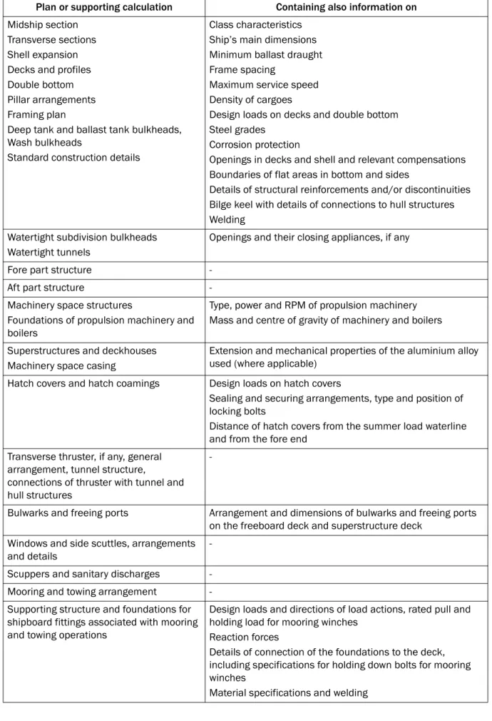
2 Documents to be Submitted ...37
3 Scope of Approval...40
4 Workmanship ...41
5 Structural Details...41
6 Equivalence Procedures...41
SECTION 4 Symbols and Definitions... 43
1 Primary Symbols and Units ...43
2 Symbols ...44
3 Definitions ...47
SECTION 5 Loading Manual and Loading Instruments... 61
1 General Requirements ...61
2 Loading Manuals ...61
3 Loading Instrument ...64
4 Loading Specific to Bulk Carriers...65
Chapter 2: General Arrangement Design...67
SECTION 1 General... 69
1 General ...69
SECTION 2 Subdivision Arrangement... 70
1 Watertight Bulkhead Arrangement...70
2 Collision Bulkhead ...71
3 Aft Peak Bulkhead ...71
SECTION 3 Compartment Arrangement ... 73
1 Cofferdams...73
2 Double Bottom ...74
3 Double Side...74
4 Fore End Compartments ...75
5 Fuel Oil Tanks...75
6 Aft End Compartments ...75
7 Ballast Tanks...76
PA R T 1
IACS
SECTION 4
Access Arrangement... 77
1 Closed spaces ...77
2 Cargo Area and Forward Spaces...77
Chapter 3: Structural Design Principles...79
SECTION 1 Materials... 81
1 General ...81
2 Hull Structural Steel...81
3 Steels for Forging and Casting...85
4 Aluminium Alloys ...86
5 Other Materials and Products ...88
SECTION 2 Net Scantling Approach... 89
1 General ...89
SECTION 3 Corrosion Additions... 94
1 General ...94
SECTION 4 Corrosion Protection ... 97
1 General ...97
2 Sacrificial Anodes...97
SECTION 5 Limit States ... 98
1 General ...98
2 Criteria ... 100
3 Strength Check Against Impact Loads ... 101
SECTION 6 Structural Detail Principles ...103
1 Application... 103
2 General Principles... 103
3 Stiffeners ... 105
4 Primary Supporting Members (PSM) ... 108
5 Intersection of Stiffeners and Primary Supporting Members ... 111
6 Openings... 118
7 Double Bottom Structure... 122
8 Double Side Structure ... 127
9 Deck Structure ... 128
10 Bulkhead Structure ... 129
11 Pillars... 134
SECTION 7 Structural Idealisation ...135
1 Structural Idealisation of Stiffeners and Primary Supporting Members ... 135
2 Plates ... 152
3 Stiffeners ... 156
4 Primary Supporting Members ... 158
Chapter 4: Loads ... 159
SECTION 1 Introduction ...161
1 General ... 161
SECTION 2 Dynamic Load Cases ...164
1 General ... 165
PA R T 1
IACS
2 Dynamic Load Cases for Strength Assessment... 166
3 Dynamic Load Cases for Fatigue Assessment... 172
SECTION 3 Ship Motions and Accelerations...178
1 General ... 179
2 Ship Motions and Accelerations ... 179
3 Accelerations at any Position... 182
SECTION 4 Hull Girder Loads ...184
1 Application... 184
2 Vertical Still Water Hull Girder Loads ... 185
3 Dynamic Hull Girder Loads... 188
SECTION 5 External Loads...193
1 Sea Pressure... 194
2 External Pressures on Exposed Decks... 210
3 External Impact Pressures for the Bow Area ... 213
4 External Pressures on Superstructure and Deckhouses ... 215
5 External Pressures on Hatch Covers ... 217
SECTION 6 Internal Loads ...219
1 Pressures Due to Liquids ... 222
2 Pressures and Forces Due to Dry Bulk Cargo... 225
3 Pressures and Forces Due to Dry Cargoes in Flooded Conditions... 231
4 Steel Coil Loads in Cargo Holds of Bulk Carriers... 235
5 Loads on Non-Exposed Decks and Platforms... 240
6 Sloshing Pressures in Tanks ... 241
7 Design Pressure For Tank Testing ... 247
SECTION 7 Design Load Scenarios ...248
1 General ... 249
2 Design Load Scenarios for Strength Assessment ... 250
3 Design Load Scenarios for Fatigue Assessment ... 251
SECTION 8 Loading Conditions...252
1 Application... 252
2 Common Design Loading Conditions ... 253
3 Oil Tankers ... 255
4 Bulk Carriers... 274
5 Standard Loading Conditions for Fatigue Assessment ... 306
APPENDIX 1 Hold Mass Curves ...313
1 General ... 314
2 Maximum and Minimum Masses of Cargo in Each Hold ... 316
3 Maximum and Minimum Masses of Cargo of Two Adjacent Holds ... 322
Chapter 5: Hull Girder Strength... 327
SECTION 1 Hull Girder Yielding Strength ...329
1 Strength Characteristics of Hull Girder Transverse Sections ... 330
2 Hull Girder Bending Assessment ... 334
3 Hull Girder Shear Strength Assessment... 337
SECTION 2 Hull Girder Ultimate Strength ...348
1 Application... 348
PA R T 1
IACS
2 Checking Criteria... 348
SECTION 3 Hull Girder Residual Strength...351
1 Application... 351
2 Checking Criteria... 351
APPENDIX 1 Direct Calculation of Shear Flow...354
1 Calculation Formula... 354
2 Example of Calculations for a Single Side Hull Cross Section ... 357
APPENDIX 2 Hull Girder Ultimate Capacity ...362
1 General ... 362
2 Incremental-Iterative Method... 363
3 Alternative Methods... 373
Chapter 6: Hull Local Scantling ... 375
SECTION 1 General...377
1 Application... 377
SECTION 2 Load Application...378
1 Load Combination... 378
2 Design Load Sets ... 379
SECTION 3 Minimum Thicknesses...381
1 Plating... 381
2 Stiffeners and Tripping Brackets ... 382
3 Primary Supporting Members ... 382
SECTION 4 Plating ...383
1 Plating Subjected to Lateral Pressure ... 383
2 Special Requirements ... 385
SECTION 5 Stiffeners ...389
1 Stiffeners Subject to Lateral Pressure ... 389
SECTION 6 Primary Supporting Members and Pillars ...392
1 General ... 392
2 Primary Supporting Members Within Cargo Hold Region ... 392
3 Primary Supporting Members Outside Cargo Hold Region ... 393
4 Pillars ... 395
Chapter 7: Direct Strength Analysis ... 397
SECTION 1 Strength Assessment...399
1 General ... 399
2 Net Scantling... 400
3 Finite Element Types ... 401
4 Submission of Results ... 401
5 Computer Programs... 402
SECTION 2 Cargo Hold Structural Strength Analysis ...403
1 Objective and Scope ... 403
2 Structural Model ... 405
PA R T 1
IACS
3 FE Load Combinations ... 417
4 Load Application ... 417
5 Analysis Criteria ... 434
SECTION 3 Local Structural Strength Analysis...438
1 Objective and Scope... 438
2 Local Areas to be Assessed by Fine Mesh Analysis ... 438
3 Screening Procedure ... 442
4 Structural Modelling ... 450
5 FE Load Combinations ... 461
6 Analysis Criteria ... 461
Chapter 8: Buckling... 463
SECTION 1 General...465
1 Introduction... 465
2 Application... 465
3 Definitions ... 466
SECTION 2 Slenderness Requirements...469
1 Structural Elements... 469
2 Plates... 469
3 Stiffeners... 470
4 Primary Supporting Members ... 471
5 Brackets ... 472
6 Other Structures ... 474
SECTION 3 Prescriptive Buckling Requirements ...476
1 General ... 476
2 Hull Girder Stress... 477
3 Buckling Criteria... 479
SECTION 4 Buckling Requirements for Direct Strength Analysis...481
1 General ... 481
2 Stiffened and Unstiffened Panels... 481
3 Corrugated Bulkhead ... 491
4 Vertically Stiffened Side Shell of Single Side Skin Bulk Carrier... 493
5 Struts, Pillars and Cross Ties ... 494
SECTION 5 Buckling Capacity ...495
1 General ... 497
2 Buckling Capacity of Plates and Stiffeners ... 497
3 Buckling capacity of other structures... 515
APPENDIX 1 Stress Based Reference Stresses ...519
1 Stress based method ... 519
2 Reference Stresses ... 520
Chapter 9: Fatigue... 525
SECTION 1 General Considerations ...527
1 Rule Application for Fatigue Requirements ... 527
2 Definition ... 528
3 Assumptions... 529
4 Methodology... 529
PA R T 1
IACS
5 Corrosion Model... 531
6 Loading Conditions ... 531
7 Load Cases... 531
SECTION 2 Structural Details to be Assessed...533
1 Simplified Stress Analysis ... 533
2 Finite Element Analysis... 533
SECTION 3 Fatigue Evaluation...547
1 Fatigue Analysis Methodology... 547
2 Acceptance Criteria... 548
3 Reference Stresses for Fatigue Assessment ... 548
4 S-N Curves ... 552
5 Fatigue Damage Calculation ... 557
6 Weld Improvement Methods... 560
7 Workmanship ... 562
SECTION 4 Simplified Stress Analysis...564
1 General ... 564
2 Hot Spot Stress ... 565
3 Hull Girder Stress... 566
4 Local Stiffener Stress ... 567
5 Stress Concentration Factors... 573
SECTION 5 Finite Element Stress Analysis ...585
1 General ... 585
2 FE Modelling... 586
3 Hot Spot Stress for Details Different From Web-Stiffened Cruciform Joints ... 598
4 Hot Spot Stress for Web-Stiffened Cruciform Joint ... 600
5 Limitations of Hot Spot Stress Approach ... 603
6 Screening Fatigue Assessment... 604
SECTION 6 Detail Design Standard ...607
1 General ... 607
2 Stiffener-Frame Connections ... 608
3 Scallops in way of Block Joints ... 611
4 Hopper Knuckle Connection ... 611
5 Horizontal Stringer Heel ... 621
6 Bulkhead Connection to Lower and Upper Stool... 623
7 Bulkhead Connection to Inner Bottom ... 629
8 Lower and Upper Toe of Hold Frame... 629
9 Hatch Corner ... 631
Chapter 10: Other Structures... 633
SECTION 1 Fore Part ...635
1 General ... 635
2 Structural Arrangement ... 635
3 Structure Subjected to Impact Loads... 637
4 Additional Scantling Requirements ... 644
SECTION 2 Machinery Space ...646
1 General ... 646
2 Machinery Space Arrangement... 646
3 Machinery Foundations ... 648
PA R T 1
IACS
SECTION 3
Aft Part ...650
1 General ... 650
2 Aft Peak ... 650
3 Stern Frames... 652
4 Special Scantling Requirements for Shell Structure ... 654
SECTION 4 Tanks Subject to Sloshing ...655
1 General ... 655
2 Scantling Requirements... 659
Chapter 11: Superstructure, Deckhouses and Hull Outfitting... 663
SECTION 1 Superstructures, Deckhouses and Companionways...665
1 General ... 665
2 Structural Arrangement... 666
3 Scantlings... 667
SECTION 2 Bulwark and Guard Rails...669
1 General Requirements ... 669
2 Bulwarks... 669
3 Guard Rails... 671
SECTION 3 Equipment ...672
1 General ... 672
2 Equipment Number Calculation... 672
3 Anchoring Equipment ... 675
SECTION 4 Supporting Structure for Deck Equipment and Fittings...682
1 General ... 682
2 Anchoring Windlass and Chain Stopper... 682
3 Mooring Winches ... 686
4 Cranes, Derricks, Lifting Masts and Life Saving Appliances... 687
5 Bollards and Bitts, Fairleads, Stand Rollers, Chocks and Capstans... 689
6 Miscellaneous Deck Fittings ... 690
SECTION 5 Small Hatchways ...691
1 General ... 691
2 Small Hatchways Fitted on the Exposed Fore Deck... 693
Chapter 12: Construction ... 697
SECTION 1 Construction and Fabrication...699
1 General ... 699
2 Cut-Outs, Plate Edges... 700
3 Cold Forming ... 700
4 Hot Forming... 701
5 Assembly and Alignment ... 702
SECTION 2 Fabrication by Welding ...703
1 General ... 703
2 Welding Procedures, Welding Consumables and Welders ... 703
3 Weld Joints ... 703
4 Non-Destructive Examination (NDE)... 705
PA R T 1
IACS
SECTION 3
Design of Weld Joints ...706
1 General ... 706
2 Tee or Cross Joint... 707
3 Butt Joint... 717
4 Other Types of Joints ... 718
5 Connection Details... 720
Chapter 13: Ship in Operation - Renewal Criteria... 725
SECTION 1 Principles and Survey Requirements ...727
1 Principles ... 727
2 Hull Survey Requirements... 728
SECTION 2 Acceptance Criteria...729
1 General ... 729
2 Renewal Criteria... 730
PA R T 1
IACS
PA R T 1 CHAPTER 1
PART 1 CHAPTER 1
RULE GENERAL PRINCIPLES
Table of Contents
SECTION 1 Application
1 Scope of Application 2 Rule Application 3 Class Notations
4 Application of the Rules of the Society
SECTION 2 Rule Principles
1 General
2 General Assumptions 3 Design Basis
4 Design Principles 5 Rule Design Methods
SECTION 3
Verification of Compliance
1 General
2 Documents to be Submitted 3 Scope of Approval
4 Workmanship 5 Structural Details 6 Equivalence Procedures
SECTION 4
Symbols and Definitions
1 Primary Symbols and Units 2 Symbols
3 Definitions
SECTION 5
Loading Manual and Loading Instruments
1 General Requirements 2 Loading Manuals 3 Loading Instrument
4 Loading Specific to Bulk Carriers
PA R T 1 CHAPTER 1
PA R T 1 CHAPTER 1 SECTION 1
IACS SECTION 1
APPLICATION
1 SCOPE OF APPLICATION
1.1 General
1.1.1
These Rules apply to the following ships:
a) Bulk carriers and double hull oil tankers and;
b) Being self-propelled ships with unrestricted navigation, and;
c) Contracted for construction on or after 1st July 2015.
Note 1: Unrestricted navigation means that the ship is not subject to any geographical restrictions (i.e. any oceans, any seasons) except that limited by the ship’s capability for operation in ice.
Note 2: The ‘contracted for construction’ means the date on which the contract to build the ship is signed between the prospective owner and the builder. For further details regarding the date of ‘contracted for construction’, refer to IACS Procedural Requirement (PR) No. 29.
1.1.2
These Rules apply to ships constructed of welded steel structures and composed of stiffened plate panels. The ship’s structure is to be longitudinally or transversely framed with full transverse bulkheads and intermediate web frames.
The typical arrangements of ships covered by the rules assume that the structural arrangements include:
• Double bottom, the depth of which is to be in accordance with applicable statutory requirements.
• Engine room located aft of the cargo tank/hold region.
1.1.3
Ships for which these Rules are not applicable are to comply with the relevant Rules of the Society.
1.2 Scope of application for bulk carriers
1.2.1
These Rules apply to the hull structures of single side skin and double side skin bulk carriers having a length L of 90 m or above.
Bulk carriers are ships which are constructed generally with single deck, double bottom, hopper side tanks and topside tanks and with single or double side skin construction in cargo hold region and intended primarily to carry dry cargoes in bulk. Typical arrangements of bulk carriers are shown in Figure 1.
Hybrid bulk carriers, where at least one cargo hold is constructed with hopper tank and topside tank, see typical arrangements in Figure 1, and other cargo holds are constructed without hopper tank and/or topside tanks, see examples of a transverse section in Figure 2, are to comply with the strength criteria defined in these Rules.
PA R T 1 CHAPTER 1 SECTION 1
IACS
These Rules are not applicable to the following ship types:
• Ore carriers.
• Combination carrier.
• Woodchip carrier.
• Cement, fly ash and sugar carriers provided that loading and unloading is not carried out by grabs heavier than 10 tons, power shovels and other means which may damage cargo hold structure.
• Ships with inner bottom construction adapted for self-unloading.
Figure 1 : Typical arrangements of bulk carriers
Figure 2 : Examples of transverse sections of cargo hold without hopper tank and/or topside tank
1.3 Scope of application for oil tankers
1.3.1 Length and structural arrangement application
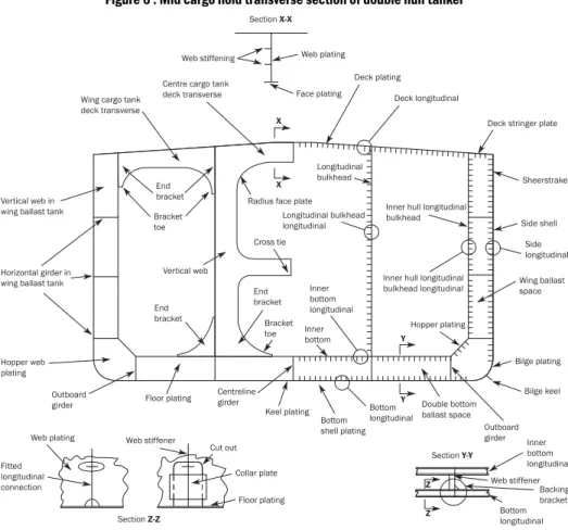
These Rules apply to the hull structures of double hull oil tankers having length L of 150 m or above. Oil tanker is defined as a ship which has to comply with Annex I of MARPOL73/78.
The typical arrangements of oil tankers covered by the rules are shown in Figure 3 and assume that the structural arrangements include:
• Double side structure with breadth in accordance with statutory requirements.
• Side longitudinal, centreline longitudinal or transverse bulkheads of plane, corrugated or double skin construction.
• Single deck structure.
The cross sections shown in Figure 3 are typical examples only and other variations of cross tie and web frame arrangements are also covered.
PA R T 1 CHAPTER 1 SECTION 1
IACS
1.3.2 Cargo temperature application
The Rules are based on the following design temperatures for the cargo:
a) maximum temperature: 80°C b) minimum temperature: 0°C.
Figure 3 : Typical arrangements of double hull oil tankers
2 RULE APPLICATION
2.1 Rule description
2.1.1 Rule structure
The rules contain 2 parts:• Part 1: General hull requirements.
• Part 2: Ship types.
The parts are structured in chapters giving instructions for detail application and requirements which are applied in order to satisfy the rule objectives.
PA R T 1 CHAPTER 1 SECTION 1
IACS
2.1.2 Numbering
The system of numbering is given in Table 1.
Table 1 : Rule numbering and abbreviations
2.2 Rule Requirements
2.2.1 Part 1
Part 1 of the Rules provides requirements common to all ship types as follow:
• Chapter 1: Rule General Principles.
• Chapter 2: General Arrangement Design.
• Chapter 3: Structural Design Principles.
• Chapter 4: Loads.
• Chapter 5: Hull Girder Strength.
• Chapter 6: Hull Local Scantling.
• Chapter 7: Direct Strength Analysis.
• Chapter 8: Buckling.
• Chapter 9: Fatigue.
• Chapter 10: Other Structure.
• Chapter 11: Superstructure, Deckhouses and Hull Outfitting.
• Chapter 12: Construction.
• Chapter 13: Ship in Operation - Renewal Criteria.
The provisions of the Ch 1, 2, 3, 4, 5, 6, 8, 12, 13 and Ch 10, Sec 4 are applicable all over the ships length.
The Ch 7, 9, 10 and 11 define their own scope of application.
2.2.2 Part 2
Part 2 of the Rules provides requirements coming in addition to those of Part 1 specific for ship types and is divided as follow:
• Chapter 1: Bulk Carriers.
• Chapter 2: Oil Tankers.
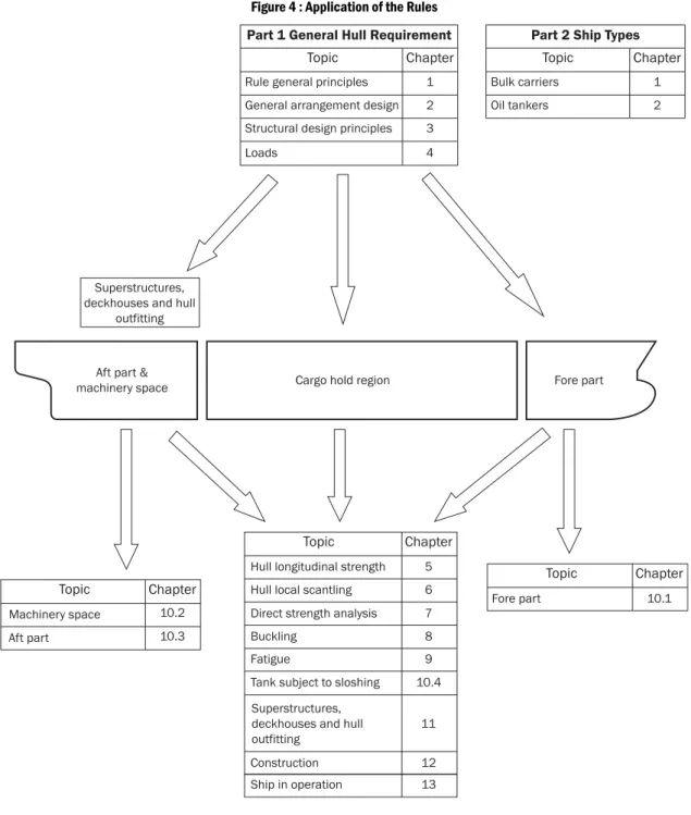
2.2.3 Application of the Rules
The ship arrangement and scantlings are to comply with the relevant parts and chapters of the Rules as it is given in Figure 4.
Order Levels Example Abbreviations
1 Part Part 1 – General Hull Requirements Pt 1
2 Chapter Chapter 1 – Rule General Principle Ch 1
3 Section Section 1 – Application Sec 1
4 Article 1. Scope of Application [1]
5 Sub-article 1.1 General [1.1]
6 Requirements 1.1.1 These Rules apply to... [1.1.1]
PA R T 1 CHAPTER 1 SECTION 1
IACS
Figure 4 : Application of the Rules
2.2.4 General criteria
The ship arrangement, the proposed details and the offered scantling in net or gross, as the case may, are to comply with the requirements and the minimum scantling given in the Rules.
2.3 Structural requirements
2.3.1 Materials and welding
The Rules applies to welded hull structures made of steel having characteristics complying with requirements in Ch 3, Sec 1. The Rules applies also to welded steel ships in which parts of the hull, such as superstructures or small hatch covers, are built in material other than steel, complying with requirements in Ch 3, Sec 1.
Ships whose hull materials are different than those given in the first paragraph are to be individually considered by the Society, on the basis of the principles and criteria adopted in the present rules.
PA R T 1 CHAPTER 1 SECTION 1
IACS
2.4 Ship parts
2.4.1 General
For the purpose of application of the present rules, the ship is considered as divided into the following five parts:
• Fore part.
• Cargo hold region.
• Machinery space.
• Aft part.
• Superstructures and deckhouses.
2.4.2 Fore part
The fore part is that part of the ship located forward of the collision bulkhead, i.e.:
• The fore peak structures.
• The stem.
2.4.3 Cargo hold region
The cargo hold region is the part of the ship that contains cargo holds, cargo tanks, and slop tanks. It includes the full breadth and depth of the ship, the collision bulkhead and the transverse bulkhead at its aft end. The cargo hold region does not include the pump room, if any.
2.4.4 Machinery space
The machinery space is the part of the ship between the aft peak bulkhead and the transverse bulkhead at the aft end of the cargo hold region and includes the pump room, if any.
2.4.5 Aft part
The aft part includes the structures located aft of the aft peak bulkhead.
2.4.6 Superstructures and deckhouses
A superstructure is a decked structure on the freeboard deck extending from side to side of the ship or with the side plating not being inboard of the shell plating more than 0.04 B.
A deckhouse is a decked structure on the freeboard or superstructure deck which does not comply with the definition of a superstructure.
2.5 Limits of application to lifting appliances
2.5.1 Definition
The fixed parts of lifting appliances, considered as an integral part of the hull, are the structures permanently connected by welding to the ship’s hull (for instance, crane pedestals, masts, king posts, derrick heel seatings, etc, excluding cranes, derrick booms, ropes, rigging accessories, and, generally, any removable parts), only for that part directly interacting with the hull structure.
2.5.2 Rule application for lifting appliances
The fixed parts of lifting appliances and their connections to the ship’s structure may be covered by the Society’s rules for lifting appliances, and/or by the certification (especially the issuance of the Register of ship’s lifting appliances and cargo handling gear) of lifting appliances when required.
PA R T 1 CHAPTER 1 SECTION 1
IACS
2.5.3 Structures supporting fixed lifting appliances
The design of the structure supporting fixed lifting appliances and the structure that might be called to support a mobile appliance is to be designed taking into account the additional loads that may be imposed on them by the operation of the appliance and environmental conditions as declared by the builder or its sub-contractors.
2.6 Novel designs 2.6.1
Ships with novel features or unusual hull design are to comply with Ch 1, Sec 3, [6.2].
3 CLASS NOTATIONS 3.1 Class notation CSR
3.1.1 Application
In addition to the class notations granted by the Society and to the service features and additional class notations defined hereafter, ships fully complying with these Rules are assigned the notation CSR.
3.2 Class notation for bulk carriers
3.2.1 Additional service features BC-A, BC-B and BC-C
The following requirements apply to ships, as defined in [1.2.1], having length L of 150 m or above.
Bulk carriers are to be assigned one of the following additional service features:
a) BC-A: For bulk carriers designed to carry dry bulk cargoes of cargo density 1.0 t/m3 and above with specified holds empty at maximum draught in addition to BC-B conditions.
b) BC-B: For bulk carriers designed to carry dry bulk cargoes of cargo density of 1.0 t/m3 and above with all cargo holds loaded in addition to BC-C conditions.
c) BC-C: For bulk carriers designed to carry dry bulk cargoes of cargo density less than 1.0 t/m3.
The following additional service features are to be provided giving further detailed description of limitations to be observed during operation as a consequence of the design loading condition applied during the design in the following cases:
• {Maximum cargo density in t/m3} for additional service features BC-A and BC-B if the maximum cargo density is less than 3.0 t/m3, see also Ch 4, Sec 8, [4.1].
• {No MP} for all additional service features when the ship has not been designed for loading and unloading in multiple ports in accordance with the conditions specified in Ch 4, Sec 8, [4.2.2].
• {Holds a, b, … may be empty} for additional service feature BC-A, see also Ch 4, Sec 8, [4.1].
• {Block loading} for additional service feature BC-A, when the ship is intended to operate in alternate block load condition, see also Ch 4, Sec 8, [4.2.3], item d.
3.2.2 Additional class notation GRAB [X]
The additional class notation GRAB [X] is mandatory for ships having one of the additional service features BC- A or BC-B, according to [3.2.1]. For these ships, the requirements for the GRAB [X] notation given in Pt 2, Ch 1, Sec 6 are to comply with for an unladen grab weight X taken not less than:
• 35 t for ships with L ≥ 250 m,
• 30 t for ships with 200 m ≤ L < 250 m,
• 20 t otherwise.
For all other ships, the additional class notation GRAB [X] is voluntary.
PA R T 1 CHAPTER 1 SECTION 1
IACS
4 APPLICATION OF THE RULES OF THE SOCIETY
4.1 Structural parts not covered by these Rules
4.1.1
Designer should take care that parts of the structure that these Rules do not cover comply with the relevant requirements of the Society’s Rule.
PA R T 1 CHAPTER 1 SECTION 2
IACS SECTION 2
RULE PRINCIPLES
1 GENERAL
1.1 Rule objectives
1.1.1
The objectives of the Rules are to establish the classification minimum requirements to mitigate the risks of major hull structural failure in order to help improve the safety of life, environment and property and to contribute to the durability of the hull structure for the ship’s design life.
1.1.2
The sub-sections contain:
• The general assumptions pertaining to the design, construction and operation of the ship and give information on the assumed roles of the Society, builders, designers and owners.
• The design basis which specifies the premises on which the Rules are based in terms of design parameters and assumptions about the ship operation.
• The design principles which define the fundamental principles used for the structural requirements in the Rules with respect to loads and structural capacity.
• The rule design methods which describe how the design principles are applied and the criteria are used in view of [1.1.1].
2 GENERAL ASSUMPTIONS
2.1 International and national regulations
2.1.1
Ships are to be designed, constructed and operated in compliance with the regulatory framework prescribed by the International Maritime Organisation (IMO) and implemented by National Administrations or the Society on their behalf. The builder is to give due consideration to the influence on the structural design and arrangement from the relevant requirements of the International Labour Organization (ILO) implemented by National Administrations or the Society on their behalf.
2.1.2
The Rules are based on the assumption that the applicable statutory requirements are complied with.
2.2 Application and implementation of the Rules
2.2.1
The Society develops and publishes the rules for classification of ships, containing minimum requirements for the hull structure and essential engineering systems. The Society verifies compliance with the classification requirements and the applicable international regulations when authorised by a National Administration during design, construction and operation of the ship.
PA R T 1 CHAPTER 1 SECTION 2
IACS
2.2.2
These Rules address the hull structural aspects of classification and do not include requirements related to the verification of compliance with the Rules during construction and operation. In order to achieve the safety level targeted by the Rules, a number of aspects related to design, construction and operation of the ship are assumed to be adhered to by the parties involved in the application and implementation of the Rules. A summary of these assumptions are given in the following:
a) General aspects:
• Relevant information and documentation involved in the design, construction and operation is communicated between the builder, the designer, the Society and the owner as agreed between builder and owner. Design documentation according to Rule requirements is provided.
• Quality systems are applied to the design, construction, operation and maintenance activities by owners and other relevant parties to ensure the compliance with the requirements of the Rules.
b) Design aspects:
• The owner specifies the intended use of the ship, and the ship is designed according to operational requirements as well as the structural requirements given in the Rules.
• The builder identifies and documents the operational limits for the ship so that the ship can be safely and efficiently operated within these limits.
• Verification of the design is performed by the builder to check compliance with provisions contained in the Rules in addition to national and international regulations.
• The design is performed by appropriately qualified, competent and experienced personnel.
• The Society performs a technical appraisal of the design plans and related documents for a ship to verify compliance with the appropriate classification Rules.
• For spaces where lighting and ventilation are to be fitted, the builder is to give consideration to the influence on the structural design and arrangement from the relevant requirements of International Conventions such as SOLAS and MLC2006 Regulation 3.1 - Accommodation and recreational facilities, and Society's rules if any. For general guidance, human element factors may be considered based on IACS Recommendation No. 132 and/or an ergonomic standard accepted by the Society.
• For spaces normally occupied or manned by shipboard personnel where noise is to be minimised, the builder is to give consideration to the influence on the structural design and arrangement from the relevant requirements of SOLAS Ch II-1, Reg.3-12 and "The Code on Noise Levels Onboard Ships" adopted at MSC.337(91).
• For spaces normally occupied or manned by shipboard personnel where vibration is to be minimised, the builder is to give consideration to the influence on the structural design and arrangement from the relevant requirements of relevant statutory requirements such as MLC 2006 Regulation 3.1 - Accommodation and recreational facilities. For general guidance, human element factors may be considered based on IACS Recommendation No. 132 or on an ergonomic standard accepted by the Society.
c) Construction aspects:
• The builder provides adequate supervision and quality control during the construction.
• Construction is carried out by qualified and experienced personnel.
• Workmanship, including alignment and tolerances, is in accordance with acceptable shipbuilding standards.
• The Society performs surveys to verify that the construction and quality control are in accordance with the classification features of approved plans and procedures.
d) Operational aspects:
• Personnel involved in operations are aware of, and comply with, the operational limitations of the ship.
PA R T 1 CHAPTER 1 SECTION 2
IACS
• Operations personnel receive sufficient training such that the ship is properly handled so that the loads and resulting stresses imposed on the structure are minimised.
• The ship is maintained in adequate condition and in accordance with the Society survey scheme and international and national regulations and requirements.
• The Society performs surveys to verify that the ship is maintained in class in accordance with the Society survey scheme.
3 DESIGN BASIS 3.1 General
3.1.1
This sub-section specifies the design parameters and the assumptions about the ship operation that are used as the basis of the design principles of the Rules.
3.1.2
Ships are to be designed to withstand, in the intact condition, the environmental conditions as defined in [5.3.2] and [5.3.3] anticipated during the design life, for the appropriate loading conditions. Structural strength is to be determined against buckling and yielding. Ultimate strength calculations have to include ultimate hull girder capacity and ultimate strength of plates and stiffeners.
3.1.3 Residual strength
Ships having a length L of 150 m or above are to be designed to have sufficient reserve strength to withstand the loads in damaged conditions, e.g. collision, grounding or flooded scenarios. Residual strength calculations are to take into account the ultimate reserve capacity of the hull girder, considering permanent deformation and post-buckling behaviour as specified in Ch 5, Sec 3.
3.1.4 Finite element analysis
The scantling of the structural members within the cargo hold region of ships having a length L of 150 m or above is to be assessed according to the requirements specified in Pt 1, Ch 7.
3.1.5 Fatigue life
Ships having a length L of 150 m or above are to be assessed according to the design fatigue life for structural details specified in Pt 1, Ch 9.
3.1.6
The Rules are applicable for ships in compliance with the specified design basis. Special consideration is given to deviations from this design basis.
3.1.7
The design basis used for the design of each ship, as communicated by the builder to the owner, is to be documented and submitted to the Society as part of the design review and approval. All changes of the design basis are to be formally advised to the Society and the owner for approval.
3.2 Hull form limit
3.2.1
The Rules assume the following hull form with respect to environmental loading:
• L < 500 m
PA R T 1 CHAPTER 1 SECTION 2
IACS
• CB > 0.6
• L/B > 5
• B/D < 2.5
For ships over 350 m in length, special consideration is to be made for the wave loads by the Society.
3.3 Design life
3.3.1
A design life of 25 years is assumed for selecting ship design parameters. The specified design life is the nominal period that the ship is assumed to be exposed to operating conditions.
3.4 Environmental conditions
3.4.1
North Atlantic wave environmentThe rule requirements are based on a ship trading in the North Atlantic wave environment for its entire design life.
3.4.2
Wind and currentThe effects of wind and current with regard to the strength of the structure are not considered.
3.4.3 Ice
The effects of ice and ice accretion are not taken into account by the Rules.
3.4.4 Design temperatures
The Rules assume that the structural assessment of hull strength members is valid for the following design temperatures:
• Lowest mean daily average temperature in air is -10°C.
• Lowest mean daily average temperature in seawater is 0°C.
Ships intended to operate in areas with lower mean daily average temperature, e.g. regular service during winter seasons to Arctic or Antarctic waters are subject to the requirements as specified by the Society.
In the above, the following definitions apply:
Mean : Statistical mean over observation period (at least 20 years).
Daily Average : Average during one day and night.
Lowest : Lowest during year.
For seasonally restricted service the lowest value within the period of operation applies.
3.4.5 Thermal loads
The effects of thermal loads and residual stresses are not taken into account in the Rules.
3.5 Operating conditions
3.5.1
The Rules specify minimum loading conditions that are to be assessed for compliance.
Specification of loading conditions other than those required by the Rules is the responsibility of the owner.
These other loading conditions are to be documented and also be assessed for compliance.
PA R T 1 CHAPTER 1 SECTION 2
IACS
3.5.2
The Rules assume the following:
• The ballast cargo hold of bulk carriers is not to be partly filled in seagoing operations.
• Ballasting and deballasting operations in the ballast cargo hold of bulk carriers are not to be performed when the weather is not fair.
3.6 Operating draughts
3.6.1
The design operating draughts are to be specified by the builder/designer subject to acceptance by the owner and are to be used to derive the appropriate structural scantlings. All operational loading conditions in the loading manual are to comply with the specified design operating draughts. The following design operating draughts are as a minimum to be considered:
• Scantling draught for the assessment of structure.
• Minimum ballast draught at midship for assessment of structure.
• Minimum heavy ballast draught at midship for assessment of bulk carrier structure.
• Minimum forward draughts for the assessment of bottom structure forward subjected to slamming loads, TF-e and TF-f, with and without ballast tanks in way filled.
TF-e and TF-f are defined in Ch 4, Sec 5, [3.2.1]
• For oil tankers: maximum draughts amidships for both conditions:
• with all cargo tanks abreast empty.
• with centre cargo tank empty and wing cargo tanks full.
• with centre cargo tank full and wing cargo tanks empty.
• For bulk carriers carrying steel coils: maximum draught amidships for steel coil loading conditions.
3.7 Internal environment
3.7.1 Oil cargo density for strength assessment
A density of 1.025 t/m3, or a higher value if specified by the designer, is to be used for oil cargoes for the strength assessment of all relevant tank structures.
3.7.2 Oil cargo density for fatigue assessment
For the fatigue assessment of cargo tank structures, the mean density is to be taken as 0.9 t/m3, or a higher value if specified by the designer.
3.7.3 Dry cargo density
The density for dry bulk cargo is to be taken according to the specifications in Ch 4, Sec 6, [2.3].
3.7.4 Water ballast density
A density of 1.025 t/m3 is to be used for water ballast.
3.8 Structural construction and inspection
3.8.1
The structural requirements included in the Rules are developed with the assumption that construction and repair follow acceptable shipbuilding and repair standards and tolerances. The Society may require that
PA R T 1 CHAPTER 1 SECTION 2
IACS
additional attention is paid to critical areas of the structure by the builder during construction and by the owner for repair after the ship’s delivery.
3.8.2
As an objective, ships are to be built in accordance with controlled quality production standards using approved materials as necessary.
3.8.3
The Rules define the renewal criteria for the individual structural items. The structural requirements included are developed on the assumption that the structure is subject to appropriate monitoring by the owner once the ship is in operation and to periodical survey in accordance with Society rules and regulations.
3.8.4
Tank strength and tightness testing are to be carried out as a part of the verification scheme according to the Rules and/or documents of the individual Society which incorporate IACS UR S14.
3.8.5
Specifications for material manufacturing, assembling, joining and welding procedures, steel surface preparation and coating are to be included in the ship construction quality procedures. It is assumed that the owner has approved these builder specifications.
3.9 Maximum service speed
3.9.1
The maximum service speed is to be specified in the design specification. Although the hull structure verification criteria takes into account the service speed this does not relieve the responsibilities of the owner and personnel to properly handle the ship, see item (d) in [2.2.2].
3.10 Owner’s extras
3.10.1
Owner’s specification of requirements above the general classification or statutory requirements may affect the structural design. Owner’s extras may include requirements for:
• Vibration analysis.
• Maximum percentage of high strength steel.
• Additional scantlings above that required by the Rules.
• Additional design margin on the loads specified by the Rules, etc.
• Improved fatigue resistance, in the form of a specified increase in design fatigue life or equivalent.
Owner’s extras are not specified by these Rules. Owner’s extras, if any, that may affect the structural design are to be clearly specified in the design documentation.
4 DESIGN PRINCIPLES
4.1 Overall principles
4.1.1 Introduction
This sub-section defines the underlying design principles of the Rules in terms of loads, structural capacity models and assessment criteria and also construction and in-service aspects.
PA R T 1 CHAPTER 1 SECTION 2
IACS
4.1.2 General
The Rules are based on the following overall principles:
• The safety of the structure can be assessed by addressing the potential structural failure mode(s) when the ship is subjected to operational loads and environmental loads/conditions.
• The design complies with the design basis, see Ch 1, Sec 3.
• The structural requirements are based on consistent design load sets which cover the appropriate operating modes of a bulk carrier or oil tanker.
The ship’s structure is designed such that:
• It has a degree of redundancy. The ship’s structure should work in a hierarchical manner and, in principle, failure of structural elements lower down in the hierarchy do not result in immediate consequential failure of elements higher up in the hierarchy.
• It has sufficient reserve strength to withstand the wave and internal loads in damaged conditions that are reasonably foreseeable e.g. collision, grounding or flooding scenarios. Residual strength calculations are to take into account the ultimate reserve capacity of the hull girder, considering permanent deformation and post-buckling behaviour.
• The incidence of in-service cracking is minimised, particularly in locations which affect the structural integrity or containment integrity, affect the performance of structural or other systems or are difficult to inspect and repair.
• It has adequate structural redundancy to survive in the event that the structure is accidentally damaged by a minor impact leading to flooding of any compartment.
4.1.3 Limit state design principles
The rules are based on the principles of limit state design.
Limit state design is a systematic approach where each structural element is evaluated with respect to possible failure modes related to the design scenarios identified. For each retained failure mode, one or more limit states may be relevant. By consideration of all relevant limit states, the limit load for the structural element is found as the minimum limit load resulting from all the relevant limit states.
The limit states defined in Ch 3, Sec 5 are divided into the four categories: Serviceability Limit State (SLS), Ultimate Limit State (ULS), Fatigue Limit State (FLS) and Accidental Limit State (ALS).
The Rules include requirements to cover the relevant limit states for the various parts of the structure.
4.2 Loads
4.2.1 Design load scenarios
The structural assessment of the structure is based on the design load scenarios encountered by the ship.
Refer to Ch 4, Sec 7.
The design load scenarios are based on static and dynamic loads as given below:
• Static design load scenario (S):
Covers application of relevant static loads and typically covers load scenarios in harbour, sheltered water, or tank testing.
• Static plus Dynamic design load scenario (S+D):
Covers application of relevant static loads and simultaneously occurring dynamic load components and typically cover load scenarios for seagoing operations.
• Impact design load scenario (I):
Covers application of impact loads such as bottom slamming and bow impact encountered during seagoing operations.
PA R T 1 CHAPTER 1 SECTION 2
IACS
• Sloshing design load scenario (SL):
Covers application of sloshing loads encountered during seagoing operations.
• Fatigue design load scenario (F):
Covers application of relevant dynamic loads.
• Accidental design load scenario (A):
Covers application of some loads not occurring during normal operations.
4.3 Structural capacity assessment
4.3.1 General
The basic principle in structural design is to apply the defined design loads, identify plausible failure modes and employ appropriate capacity models to verify the required structural scantlings.
4.3.2 Capacity models for ULS, SLS and ALS
The strength assessment method is to be capable of analysing the failure mode in question to the required degree of accuracy.
The structural capacity assessment methods are in either a prescriptive format or require the use of more advanced calculations such as finite element analysis methods.
The formulae used to determine stresses, deformations and capacity are deemed appropriate for the selected capacity assessment method and the type and magnitude of the design load set.
4.3.3 Capacity models for FLS
The fatigue assessment method provides Rule requirements to assess structural details against fatigue failure.
The fatigue capacity model is based on a linear cumulative damage summation (Palmgren-Miner’s rule) in combination with a design S-N curve, a reference stress range and an assumed long-term stress distribution curve.
The fatigue capacity assessment models are in either a prescriptive format or require the use of more advanced calculations, such as finite element analysis methods. These methods account for the combined effects of global and local dynamic loads.
4.3.4 Net scantling approach
The objective of the net scantling approach is to:
• Provide a relationship between the thickness used for strength calculations during the newbuilding stage and the minimum thickness accepted during the operational phase.
• Enable the status of the structure with respect to corrosion to be clearly ascertained throughout the life of the ship.
The net scantling approach distinguishes between local and global corrosion. Local corrosion is defined as uniform corrosion of local structural elements, such as a single plate or stiffener. Global corrosion is defined as the overall average corrosion of larger areas, such as primary supporting members and the hull girder. Both the local and global corrosion are used as a basis for the newbuilding review and are to be assessed during operation of the ship.
No credit is given in the assessment of structural capability for the presence of coatings or similar corrosion protection systems.
The application of the net thickness approach to assess the structural capacity is specified in Ch 3, Sec 2.
4.3.5 Intact structure
All strength calculations for ULS, SLS and FLS are based on the assumption that the structure is intact. The residual strength of the ship in a structurally damaged condition is assessed for ALS.
PA R T 1 CHAPTER 1 SECTION 2
IACS
5 RULE DESIGN METHODS
5.1 General
5.1.1 Design methods
Scantling requirements are specified to cover the relevant limit states (ULS, SLS, FLS and ALS) as necessary for various structural parts.
The criteria for the assessment of the scantlings are based on one of the following design methods:
• Working Stress Design (WSD) method, also known as the permissible or allowable stress method.
• Partial Safety Factor (PSF) method, also known as Load and Resistance Factor Design (LRFD).
For both WSD and PSF, two design assessment conditions and corresponding acceptance criteria are given.
These conditions are associated with the probability level of the combined loads, A and B.
• The WSD method has the following composition:
where:
Wstat : Simultaneously occurring static loads (or load effects in terms of stresses).
Wdyn : Simultaneously occurring dynamic loads. The dynamic loads are typically a combination of local and global load components.
R : Characteristic structural capacity (e.g. specified minimum yield stress or buckling capacity).
ηi : Permissible utilisation factor (resistance factor). The utilisation factor includes consideration of uncertainties in loads, structural capacity and the consequence of failure.
• The PSF method has the following composition:
where:
γstat-i : Partial safety factor that accounts for the uncertainties related to static loads.
γdyn-i : Partial safety factor that accounts for the uncertainties related to dynamic loads.
γR : Partial safety factor that accounts for the uncertainties related to structural capacity.
The acceptance criteria for both the WSD method and PSF method are calibrated for the various requirements such that consistent and acceptable safety levels for all combinations of static and dynamic load effects are derived.
5.2 Minimum requirements
5.2.1
Minimum requirements specify the minimum scantling requirements which are to be applied irrespective of all other requirements, hence thickness below the minimum is not allowed.
The minimum requirements are usually in one of the following forms:
• Minimum thickness, which is independent of the specified minimum yield stress.
• Minimum stiffness and proportion, which are based on buckling failure modes.
for condition A.
for condition B.
for condition A.
for condition B.
Wstat ≤ η1R Wstat+Wdyn ≤ η2R
γstat 1– Wstat γdyn 1– Wdyn R γR
≤ ---- +
γstat 2– Wstat γdyn 2– Wdyn R γR
≤ ---- +
PA R T 1 CHAPTER 1 SECTION 2
IACS
5.3 Load-capacity based requirements
5.3.1 General
In general, the Working Stress Design (WSD) method is applied in the requirements, except for the hull girder ultimate strength criteria where the Partial Safety Factor (PSF) method is applied. The partial safety factor format is applied for this highly critical failure mode to better account for uncertainties related to static loads, dynamic loads and capacity formulations.
The identified load scenarios are addressed by the Rules in terms of design loads, design format and acceptance criteria set, as given in Table 2. The table is schematic and only intended to give an overview.
Load based prescriptive requirements provide scantling requirements for all plating, local support members, most primary supporting members and the hull girder and cover all structural elements including deckhouses, foundations for deck equipment.
In general, these requirements explicitly control one particular failure mode and hence several requirements may be applied to assess one particular structural member.
5.3.2 Design loads for SLS, ULS and ALS
The structural assessment of compartment boundaries, e.g. bulkheads, is based on loading condition deemed relevant for the type of ship and the operation the ship is intended for.
To provide consistency of approach, standardised Rule values for parameters, such as GM, Rroll, Tsc and CB are applied to calculate the Rule load values.
The probability level of the dynamic global, local and impact loads (see Table 1) is 10-8 and is derived using the long-term statistical approach.
The probability level of the sloshing loads (see Table 1) is 10-4.
The design load scenarios for structural verification apply the applicable simultaneously acting local and global load components. The relevant design load scenarios are given in Ch 4, Sec 7.
The simultaneously occurring dynamic loads are specified by applying a dynamic load combination factor to the dynamic load values given in Ch 4. The dynamic load combination factors that define the dynamic load cases are given in Ch 4, Sec 2.
Design load conditions for the hull girder ultimate strength are given in Ch 5, Sec 2.
5.3.3 Design loads for FLS
For the fatigue requirements given in Ch 9, the load assessment is based on the expected load history and an average approach is applied. The expected load history for the design life is characterised by the 10-2 probability level of the dynamic load value, the load history for each structural member is represented by Weibull probability distributions of the corresponding stresses.
The considered wave induced loads include:
• Hull girder loads (i.e. vertical and horizontal bending moments).
• Dynamic wave pressures.
• Dynamic pressure from cargo.
The load values are based on Rule parameters corresponding to the loading conditions, e.g. GM, CB, and the applicable draughts at amidships.
The simultaneously occurring dynamic loads are accounted for by combining the stresses due to the various dynamic load components. The stress combination procedure is given in Ch 9.
PA R T 1 CHAPTER 1 SECTION 2
IACS
Table 1 : Load scenarios and corresponding rule requirements
Table 2 : Acceptance criteria - prescriptive requirements
Operation Load type
Design load scenario (specified in Ch 4, Sec 7)
Acceptance criteria (specified in Ch 6
and Ch 7) Seagoing operations
Transit
Static and dynamic loads in heavy
weather S + D AC-SD
Impact loads in heavy weather Impact
(I) AC-I
Internal sloshing loads Sloshing
(SL) AC-S
Cyclic wave loads Fatigue
(F) -
BWE by flow through or sequential methods
Static and dynamic loads in heavy
weather S + D AC-SD
Harbour and sheltered operations Loading,
unloading and ballasting
Typical maximum loads during loading,
unloading and ballasting operations S AC-S
Tank testing Typical maximum loads during tank
testing operations S AC-S
Special conditions in harbour
Typical maximum loads during special operations in harbour, e.g. propeller inspection afloat or dry-docking loading conditions
S AC-S
Accidental condition Flooded
conditions
Typically maximum loads on internal watertight subdivision structure in accidental flooded conditions
A AC-SD
AC-S
Acceptance criteria
Plate panels and local support members (1)
Primary supporting members
(1) Hull girder members
Yield Buckling Yield Buckling Yield Buckling
AC-S AC-SD
Permissible stress:
Ch 6, Sec 4 Ch 6, Sec 5
Control of stiffness and proportions:
Ch 8, Sec 2
Permissible stress:
Ch 6, Sec 6 Pt 2, Ch 1, Sec 4 Pt 2, Ch 2, Sec 3
Control of stiffness and proportions:
Ch 8, Sec 1 Ch 8, Sec 2 Pillar buckling
Permissible stress:
Ch 5, Sec 1
Allowable buckling utilisation factor:
Ch 8, Sec 1, [3]
AC-I
Plastic criteria:
Ch 10, Sec 1, [3]
Control of stiffness and proportions:
Ch 8, Sec 2 Ch 10, Sec 1, [3]
Plastic criteria:
Ch 10, Sec 1, [3]
Control of stiffness and proportions:
Ch 8, Sec 2 Ch 10, Sec 1, [3]
N/A N/A
(1) Refer to Ch 10 for Other structures and to Ch 11 for Superstructure, deckhouses and hull outfitting
PA R T 1 CHAPTER 1 SECTION 2
IACS
Table 3 : Acceptance criteria - FE analysis
5.3.4 Structural response analysis
In general, the following approaches are applied for determination of the structural response to the applied design load combinations.
a) Beam theory:
• Used for prescriptive requirements.
b) FE analysis:
• Coarse mesh for cargo hold model.
• Fine mesh for local models.
• Very fine mesh for fatigue assessment.
5.4 Acceptance criteria
5.4.1 General
The acceptance criteria are categorised into three acceptance criteria sets. These are explained below and shown in Table 2 and Table 3. The specific acceptance criteria set that is applied in the rule requirements is dependent on the probability level of the characteristic combined load.
The acceptance criteria set AC-S is applied for the static design load combinations, and for the sloshing design loads. The allowable stress for such loads is lower than that for an extreme load to take into account effects of:
• Repeated yield.
• Allowance for some dynamics.
• Margins for some selected limited operational mistakes.
The acceptance criteria set AC-SD is applied for the S+D design load combinations where considered loads are extreme loads with a low probability of occurrence.
The acceptance criteria set AC-I is typically applied for impact loads, such as bottom slamming and bow impact loads.
5.4.2 Acceptance criteria
The specific acceptance criteria applied in the working stress design requirements are given in the detailed Rule requirements in Pt 1, Ch 5 to Ch 8, Ch 10, Ch 11 and Pt 2, Ch 1 and Ch 2.
To provide a general informational summary overview of the acceptance criteria, refer to Table 2 and Table 3 below for the different design load scenarios covered by these Rules for the yield and buckling failure modes.
For the yield criteria the permissible stress is proportional to the specified minimum yield stress of the material. For the buckling failure mode, the acceptance criteria are based on the control of stiffness and proportions as well as on the buckling utilisation factor.
Acceptance criteria
Cargo hold analysis Fine mesh analysis
Yield Buckling Yield
AC-S AC-SD
Permissible stress:
Ch 7, Sec 2, [5]
Allowable buckling utilisation factor:
Ch 8, Sec 1, [3]
Permissible Von Mises stress:
Ch 7, Sec 3, [6]
Screening criteria: Ch 7, Sec 3, [3.3]
PA R T 1 CHAPTER 1 SECTION 2
IACS
5.5 Design verification
5.5.1 Design verification – hull girder ultimate strength
The requirements for the ultimate strength of the hull girder are based on a Partial Safety Factor (PSF) method.
A safety factor is assigned to each of the basic variables, the still water bending moment, wave bending moment and ultimate capacity. The safety factors were determined using a structural reliability assessment approach, the long-term load history distribution of the wave bending moment was derived using ship motion analysis techniques suitable for determining extreme wave bending moments.
The purpose of the hull girder ultimate strength verification is to demonstrate that one of the most critical failure modes of a ship is controlled.
5.5.2 Design verification – global finite element analysis
The global finite element analysis is used to verify the scantlings given by the load-capacity based prescriptive requirements to better consider the complex interactions between the ship’s structural components, complex local structural geometry, change in thicknesses and member section properties as well as the complex load regime with sufficient accuracy.
A linear elastic three dimensional finite element analysis of the cargo region (a FE model length of three holds is required) is carried out to assess and verify the structural response of the proposed hull girder and primary supporting members and assist in specifying the scantling requirements for the primary supporting members.
The purpose with the finite element analysis is to verify that the stresses and buckling capability of the primary supporting members are within acceptable limits for the applied design loads.
5.5.3 Design verification – fatigue assessment
The fatigue assessment is required to verify that the fatigue life of critical structural details is adequate. A simplified fatigue requirement is applied to details such as end connections of longitudinal stiffeners using stress concentration factors (SCF) to account the actual detail geometry. A fatigue assessment procedure using finite element analysis for determining the actual hot spot stress of the geometric detail is applied to selected details. In both cases, the fatigue assessment method is based on the Palmgren-Miner linear damage model.
5.5.4 Relationship between prescriptive scantling requirements and FE analysis
The scantlings defined by the prescriptive requirements are not to be reduced by any form of alternative calculations such as FE analysis, unless explicitly stated.