Analysis of Iterative and Simulated Annealing HW/SW Co-Synthesis Algorithms for Energy-Aware Network-on-Chip Design
6
0
0
全文
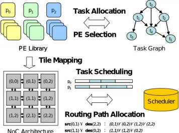
(2) paper. The Iterative algorithm evaluated here is revised from the one proposed in [14], which is originally designed for SoC system. The Iterative algorithm was modified to have the co-design step Tile Mapping, which was not necessary in SoC design, to adapt to the synthesis of NoC platform. Two SA algorithms are analyzed here. The first one is the baseline SA method that simply treats each hardware-software co-design step as an SA perturbation. The second is called Greedy PE-Selection, which first prunes the solution space of PE selection by a greedy heuristic and then invokes an SA engine to find both the hardware and software architectures. From the experimental results, the Iterative algorithm has 23% more energy consumption on the average for a set of synthetic tasks generated by TGFF[7], compared to baseline SA. However, the Iterative algorithm reduces about 65% of baseline SA execution time to find a solution. The rest of this paper is organized as follows. We present a concise specification of our co-synthesis models in Section 2. A formal problem definition is described in Section 3. The architectural co-synthesis algorithm based on iterative algorithm and SA are then described in Section 4. Next, we report our experimental results in Section 5. Finally, in Section 6 we conclude by summarizing our main contributions.. 2: System Specifications The target NoC system consists of three main components: a real-time application, an NoC-based architecture and a PE library.. 2.1: Application Model We represent a real-time application by a task graph (TG) G =< V,E >, which is a directed acyclic graph, where V represents the set of tasks and E represents the set of directed edges between tasks. Each vertex vi ∈ V has following properties: z d(vi) denotes the deadline of the node, which must be met ensure correct functionality of the application. z type(vi) denotes the type of this task node, which can be general-purpose CPU, DSP, or ASIC. z An array Ri, where the j-th element r ji ∈ R i gives the execution time of task vi if vi is executed on j-th PE pj in the PE library. z An array Si, where the j-th element s ij ∈ S i gives the energy consumption of task vi if vi is executed on j-th PE pj in the PE library. Each ei , j ∈ E represents a precedence relation (vi should be executed before vj) between vi to vj and is associated with a value c(ei,j) which indicates the amount of communication volume (bits) between vi and vj.. 2.2: NoC Model The NoC-based architecture under consideration is composed of n×n tiles interconnected by a 2D mesh network. We model such an NoC-based system with n×n tiles as an Architecture Graph (AG) N=<T,L>, which is a directed graph, where T={t1, ..., tn, ..., tn2} is the set of tiles and L is the set of links between tiles. Each link li , j ∈ L represents a link connection between ti and tj and is associated with b(li,j) which stands for the t ,t to denote bandwidth (bits/second) of li,j. We use I bits i j. the average energy consumption (in joules) of sending one bit of data from ti to tj including energy consumed in the links and switches. We use the energy model in t ,t t ,t . They define I bits as: [15, 11, 10] to calculate I bits i j. i j. ti , tj I bits = nhops × ESbit + (nhops − 1) × ELbit , where ESbit and ELbit. represent the energy consumed on the switch and on the link between tiles, respectively. The nhops is the number of routers the bit passes on its way from ti to tj. Similar to [11], we also assume a static XY routing scheme [8] as our underlying routing protocol. It first routes packets along the X-axis. Once it reaches the column where the destination tile lies in, the packet is then routed along the Y-axis. Note that the proposed co-synthesis can be easily modified to apply other deterministic routing algorithm.. 2.3: PE Model We denote the set of PEs as P={p1, ..., pn}, where indicates the i-th PE. We assume that the numbers of PEs are at least more than the number of tiles. Each pi are associated with a type(pi) which indicates the compatible task type of pi. The task vi can execute on pi if and only if is general-purpose CPU or type(pi)=type(vi).. 3: Problem Formulation For a given task graph G=<V, E>, a PE Library P={p1, ..., pn} and an NoC-based architecture N=<T, L>, the problem we want to solve is to find both the hardware and software architectures such that the overall energy consumption is minimized and specified performance constraints are met. For the overall NoC energy consumption, we break down the NoC hardware into two components: PE and interconnection. We can define the NoC co-synthesis problem as follows. Given G=<V, E>, P={p1, ..., pn}, and N=<T, L>, Find a subset P’ of P and the function ψ, ω and η such ⎪⎫ φ (ω (v ),φ (η (v ))) that ⎪⎧ S i + I bit × c(ei , j )⎬ is minimized ⎨ ∑ ω (v ) ∑ ⎪⎭ ⎪⎩∀v ∈V ∀v ∈E Subject to ∀vi ∈ V , completionTime(vi ) ≤ d (vi ) ∑ S i is the total energy consumption on PEs i. j. i. i. ∀vi∈V. and. ω ( vi ). ∑I. ∀vi , j ∈E. - 243 -. i, j. φ (ω (vi ),φ (η (v j ))) bit. × c(ei , j ). is. the. total. energy.
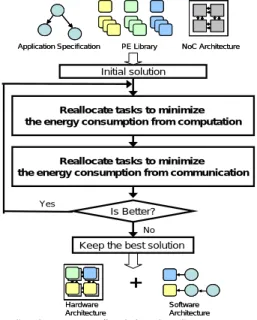
(3) consumption on interconnections (routers and links). The P’ is the result of PE Selection (PS), where |P'|=|T|. The function ψ, ω and η represent steps: Tile Mapping (TM), Task Allocation (TA) and Task Scheduling (TS) respectively and are defined as below: z Tile Mapping (TM): Map each selected PE in P' onto one of tile of the NoC. We use the function ψ: P' → T to represent “Tile Mapping” step. Obviously ψ is a one-to-one and onto function. z Task Allocation (TA): Assign each task node in V into one of compatible PE in P'. We use the function ω: V → P' to represent “Task Allocation” step. z Task Scheduling (TS): Determine the execution order of the tasks and communications. For “Task Scheduling” in our problem, the set of all possible solutions consists of all the possible permutations of the tasks subject to the additional precedence and exclusion constraints and to their deadlines. We use the function η: V → V' to represent “Task Scheduling” step.. 4: The Architectural Co-Synthesis Algorithm The architectural co-synthesis algorithms analyzed in this paper are described in this section. The three algorithms studied are the Iterative algorithm, the baseline SA method, and Greedy PE-Selection. The cost functions for all the algorithms analyzed in this paper are the same. The cost function of energy-aware HW/SW co-synthesis problem contains two parts: energy cost and miss deadline penalty. Φ = Cenergy + Cpenalty where Φ is the cost of current solution. We normalized both energy term and timing penalty term in the cost function. The energy term (Cenergy) is the same as the objective function in the problem formulation. ⎫⎪ ⎧⎪ φ (ω (v ),φ (η (v ))) i × c(ei , j )⎬ ⎨ ∑ Sω ( v ) + ∑ I bit ⎪⎭ ⎪⎩∀v ∈V ∀v ∈E and the Cpenalty is described as following: if T ≤ Td (a) Cpenalty = 0, (b) Cpenalty = T – Td + ε, if T > Td , where Td is the timing constraint of the application, T is the current completion time of the application, and ε is a constant. Recall that our optimization goal is to minimize the total energy consumption while meeting tight performance constraint. In the first case, when the current solution satisfies the specified timing constraints, we concentrate on energy consumption optimization by setting Cpenalty to zero. In the second case, the completion time T violates the timing constraint Td, therefore, both energy consumption and timing factors should be considered in searching for the solutions. The Cpenalty is given more weight as the difference between the timing constraint and the current completion time gets larger. Note that we include ε in Cpenalty to distinguish a feasible solution from an in-feasible solution. The ε is an i. experimental parameter. In this paper, we set the ε to 0.25.. 4.1: Iterative Algorithm Iterative algorithm starts with an initial solution, and iteratively improves the quality of the solution in the following iterations. The Iterative algorithm evaluated in this paper is an extension of algorithm in [14], which is targeted on SoC. We modify the Iterative algorithm by adding into the co-synthesis step of Tile Mapping, which is required in NoC platform, in the initialization step. The flow of the Iterative algorithm is illustrated in Figure 2, and synthesis process proceeds through three major steps: (1) Generate an initial solution: PEs are selected according to the m×n tasks with the highest workloads, where m and n are the dimension of the 2D mesh. The allocation of tasks is to ensure all deadlines of the tasks are met. Tile mapping of PEs is set according to the communication requirement of tasks allocated to a PE. Task scheduling is set according to the task graph, and the schedule of tasks at the same level in the task graph is set randomly. (2) Reallocate tasks to PEs and then change PEs from PE library to minimize the energy consumption.. (3) Reallocate tasks again to minimize inter-PE communication. Once a solution can minimize the energy consumption, Step (2) and Step (3) are executed iteratively as long as the two steps can get the solution with lower energy consumption.. Application Specification. NoC Architecture. Initial solution. j. i. i. PE Library. Reallocate tasks to minimize the energy consumption from computation. i, j. Reallocate tasks to minimize the energy consumption from communication Yes. Is Better? No. Keep the best solution. + Hardware Architecture. Software Architecture. Figure 2: Flow of Iterative Algorithm. - 244 -.
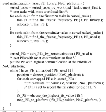
(4) void initialization ( tasks, PE_library, NoC_platform ) { sorted_tasks = sorted_tasks_by_workload ( tasks, most_first ); /* sort tasks with most-workload first */ for each task t from the first m*n tasks in sorted_tasks { this_PE = find_the_fastest_frequency_PE ( t, PE_library ); allocate( t, this_PE ); } for each task t from the remainder tasks in sorted tasked_tasks { this_PE = find_the_fastest_frequency_PE ( t, PE_used ); allocate( t, this_PE ); } sorted_PEs = sort_PEs_by_communication ( PE_used ); /* sort PEs with most-communication first */ put the PE with highest communication at the middle of NoC_platform; while ( have_PE_unmapped ( PE_used ) ) { position = choose_position ( NoC_platform ); for each unmapped PE c in sorted_PEs { fit = calculate_fit_value ( c, position, NoC_platform ); /* fit is a set to record the fit value for each PE */ } fit_PE = choose_the_highest_fit_value ( fit ); map_PE_to_platform ( fit_PE, position, NoC_platform, ); } }. Figure 3: Step of Initialization Step (1) generates an initial solution for target NoC architecture. The initial solution includes PE selection, task allocation, tile mapping and task scheduling, and the initialization process is summarized in Figure 3. All tasks are sorted according to workload, and the PEs are selected according to the first m×n tasks. The rest of the tasks are allocated to the PEs with the feasible and the fastest type to execute the task. To map the PEs onto the NoC, the PE with the highest communication is allocated to the middle of the NoC platform first, and the mapping of the rest of PEs is decided according to their fit value1 to a specific tile position. Task schedule is set according to the precedence constraint of the input task graph, and tasks at the same level in the task graph are randomly decided their priorities. In Step (2), tasks are reallocated and PEs are reselected to minimize energy consumption in PE computation. The detail algorithm of Step (2) is summarized in Figure 4. The selected PEs are sorted by their utilization first. We consider the PEs from the least to the most utilization. Given a PE p, we first reallocate tasks which reduce energy to move to another existing PEs. The PEs with tasks that can not be reallocated are replaced by a PE with lower energy consumption from the PE library. A procedure of load-balancing is required to move tasks from the most heavily utilized PEs to less utilized PEs to meet timing constraints. A feasibility test is performed at the end of Step (2) to check if the new PE selection and task allocation is a feasible solution. In Step (3), tasks are reallocated to reduce energy consumption from communication, and the procedure is illustrated in Figure 5. The algorithm considers tasks one 1. fit value = each. ∑. _ mapped. PE _ PE. i. ij. communicat PE. ij link. ion. , j is. void PE_energy_reduction_step ( tasks, PE_used, NoC_platform ) { sorted_PEs = sort_PEs_by_utilization ( PE_used, least_first ); /* sort PEs with least-utilized first */ for each PE c in sorted_PEs { reallocatable = tasks in c which can be executed on other existing PEs; /* reducible is the set of tasks allocated to PE p which cannot be moved to another PEs */ reducible = allocation ( c ) – reallocatable; x = PE from PE library with lower energy consumption which can execute all tasks in reducible; new_allocate = old allocation with reallocatable and reducible modifications; if ( schedule ( new_allocate, NoC_platform ) ) if ( reduce_energy (new_allocate, NoC_platform ) ) reallocate ( new_allocation ); /*actually reallocate the tasks*/ } }. Figure 4: Step of Computation Cost Reduction void reallocate_for_communication ( tasks, PE_used, NoC_platform ) { sorted_PEs = sort_PEs_by_communication ( PE_used, most_first ); /* sort PEs with most-communication first */ for each task t in sorted_PEs { this_PE = get_PE ( t ); /* nearby is the set of tasks adjacent to p in the data flow graph */ nearby = find_neighbor ( t, tasks ); for each task u in nearby { if ( u can be executed on this_PE ) new_allocation = old_allocation with task u moved this_PE; } if ( schedule ( new_allocate, NoC_platform ) ) if ( reduce_energy ( new_allocate, NoC_platform ) ) reallocate ( new_allocation ); /* actually reallocate the tasks */ } }. Figure 5: Step of Communication Cost Reduction at a time, and starts with the task t which conducts the most inter-task communication. The nearest-neighbor tasks to t in the task graph are then identified. Given a neighboring task u, the algorithm moves u onto t's current PE directly to reduce the communication between u and t.. 4.2: Baseline SA Algorithm The design space for the NoC hardware-software co-design problem is huge, and all of the steps in the co-design flow, PE selection, tile mapping, task allocation and scheduling, actually interplay with one another. Therefore, in this work, we propose an SA (Simulated Annealing) based hardware-software co-synthesis algorithm. The easiest way to adopt the SA approach for the co-synthesis problem is to treat each co-synthesis step (i.e., PE selection, task allocation, tile mapping and task scheduling) as a perturbation operation. We refer to this as the baseline SA algorithm. Figure 6 shows the baseline SA flow. Four steps in the NoC co-design flow (PE selection, tile mapping, task allocation and scheduling) are treated as perturbation. the position which PE will be mapped. - 245 -.
(5) Initial PE configuration. The first feasible configuration. p0 p1 p2 p3 p4 p5 p6 p7 p8 p9 p10 p11 p12 Application Specification. PE Library. …p. 97. p98 p99. NoC Architecture. Energy Consumption Low. Initial solution. Figure 7: Greedy Method for PE Selection. Perturbation PE Selection Task Allocation (PS) (TA) Tile Mapping (TM) No. 4.3: Greedy PE-Selection Method. Task Scheduling (TS). Is Feasible? Yes. Keep the best solution. + Hardware Architecture. High. PE Library. Software Architecture. Figure 6: Flow of Baseline SA Co-Synthesis Algorithm for NoC Design operations. We use the List scheduling [11, 12] as our baseline scheduler. The neighborhood structure of the four types of perturbation is given as the follows. (a) PS (PE Selection): The PS perturbation is to randomly pick pi ∈ P and swap pi and pj. Due to the heterogeneity of PE types, we have two cases for the PS perturbation: i. type(pi)=type(pj) or type(pj)=CPU: swap pi and pj directly. If the newly selected PE is the same type as the replaced PE or is a CPU, which could execute any type of tasks, the tasks running on the replaced PE can run on the new PE directly. ii. type(pi)≠type(pj) and type(pj)≠CPU: in this case, parts of the tasks running on pi may not be able to execute on pj. To handle this case, we select a CPU from P' and migrate these tasks to the selected CPU. If there is no CPU in P', we then redo the PS perturbation. (b) TM (Tile Mapping): TM is to randomly pick two tile position and swap the PEs mapped on the two position.. (c) TA (Task Allocation): TA is to pick vi ∈ V randomly and select a pi ∈ P randomly where vi is compatible with pi. Then migrate vi into pi. (d) TS (Task Scheduling): We adopt List Scheduling [11, 12] as our baseline scheduler. In List Scheduling, tasks are scheduled according to their precedence relations and priorities. In our SA-based List scheduler, TS first randomly selects vi , v j ∈ V , vi≠vj, and then swap the priority of vi and vj. Note that communication traffic is taken into account for task scheduling.. Instead of randomly choosing a PE in each SA iteration, a heuristic approach is to select PEs in a greedy method as illustrated in Figure 3. We first sort the PEs in a non-decreasing order of their energy consumption2. We then choose the first n PEs, where n is the number of tiles as our initial hardware configuration. In the example shown in Figure 3, initial P' contains p0, p1, p2 and p3 assuming a 2×2 NoC. For a selected PE configuration, we evaluate its feasibility with a low-temperature SA engine with only the TM, TA and TS perturbations. If there exist tasks that cannot be scheduled using P', we replace a PE by the CPU (CPUlowest) in the sorted PE library. The victim PE (Pv) is the PE with the maximal energy consumption in P’, and P’ = (P’ - Pv)∪CPUlowest. We repeat this process until a feasible solution is found. We then perform a normal SA run on the selected PEs to determine the corresponding tile mapping and software architecture. We can see that the greedy method only explores a subset of PE combinations. For example, the greedy method does not try the PE combination (p0, p3, p4, p5) in the example shown in Figure 3. To expand the solution space, we propose the Two-Stage SA algorithm described in the next Section.. 5: Experimental Results We use the graph generator TGFF [7] to generate random task graphs for our experiments. TGFF is a parameterizable generator that can accept user specifications like maximum in-degree, out-degree of the vertices. We generated random task graphs g1 to g15 which varies in graph size and in-out degree. A synthetic PE library was also generated for this set of tasks. The synthetic PE library contains three types of PEs: ASIC, DSP and CPU. The frequency and voltage of each type of PE was randomly generated, and there are 16 CPUs, 26 ASIC and 39 DSPs in this PE library. Figure 8 shows the energy consumption of the best solutions of 100 SA runs for various schemes on synthetic task sets. The energy consumption is normalized to the baseline SA. The experimental results show that both the Iterative algorithm and the Greedy PE-Selection method perform even worse than the baseline SA. Compared to baseline SA, Iterative algorithm has 23% more energy consumption, and the. 2. - 246 -. We compute the average energy consumption of pk by. 1 P. ∑. P. i. ski.
(6) Normalized Energy Consumption. Greedy PE-Selection. Iterative. 2.0 1.8 1.6 1.4 1.2 1.0 0.8 0.6 0.4 0.2 0.0 g1. g2. g3. g4. g5. g6. g7. g8. g9. g10. g11. g12. g13. g14. g15. average. Random Task Graphs. Figure 8: Energy Savings Comparison of Iterative and SA HW/SW Co-Synthesis Algorithms for Synthetic Task Sets Table 1: Execution Time Evaluation schemes running time Baseline SA 1 Greedy SA 1.40 Iteration 0.35 Greedy PE-Selection method has 19% more energy consumption on the average for synthetic task sets. The Greedy PE-Selection can be considered as an approach that a designer would adopt without an automatic co-design environment. The Greedy PE-Selection method can only explore a subset of PE combination, therefore, it performs worse than the baseline SA. This result demonstrates the importance of PE selection. The reason for the Iterative algorithm to perform worse than the baseline SA is that the Iterative algorithm only explores the subset of feasible solutions in each step. Moreover, the Iterative algorithm does not consider the change of Tile Mapping and Task Scheduling. Without considering Tile Mapping and Task Scheduling, the selected PEs can not switch position in the NoC platform and the tasks can not change the executable order to find more energy efficient solutions. In addition to solution quality, how fast a co-synthesis algorithm can converge is also critical. Table 1 lists the execution time of various schemes normalized to the baseline SA. The experimental results show that the Iterative algorithm is the fastest among all the evaluated algorithms. It is because the Iterative algorithm only explores the optimal solution in the subset of solution space, and this shows the Iterative algorithm sacrifice the quality of solution to get high performance.. 6: Conclusion In this paper, we analyze Iterative and SA HW/SW co-synthesis algorithms for Network-on-Chip (NoC) system design, which simultaneously optimizes both software and hardware architectures to meet a tight performance constraint. We modify the Iterative algorithm proposed for SoC system in [14] suitable for. NoC system. We also proposed two SA algorithm, baseline SA and Greedy PE-Selection. The baseline SA treats each co-design step as a perturbation, and the Greedy PE-Selection tries the PE configurations in a non-decreasing order of their energy consumption. The experimental results show the baseline SA has the best solution quality among all evaluated algorithms. Compared to the baseline SA method, the Iterative algorithm and Greedy PE-Selection have 23% and 19% more energy consumption on the average for synthetic task sets, respectively.. REFERENCES [1] ARM Processor cores. http://www.arm.com/products/CPUs/. [2] Electronics. Philips’ IP portfolio. http://www.semiconductors.philips.com. [3] Texas Instruments. Digital Signal Processing. http://focus.ti.com/dsp/docs/dsphome.tsp?sectionId=46. [4] Mpeg-2 video. is standard. I. D. 13818-2, 2001. [5] T. Adam, K. Chandy, and J. Dickson. A comparison of list schedules for parallel processing systems. Commun. ACM, 17(12):685–690, December 1974. [6] T. H. Coreman, C. E. Leiserson, R. L. Rivest, and C. Stain. Introduction to Algoirthms. McGraw Hill. [7] R. Dick, D. L. Rhodes, and W. Wolf. Tgff: Task graphs for free. March 1998. [8] C. J. Glass and L. M. Ni. The turn model for adaptive routing. pages 278–287, May 1992. [9] M. Grajcar. Strengths and weakness of genetic list scheduling for heterogeneous systems. pages 123–132, June 2001. [10] J. Hu and R. Marculescu. Energy-aware mapping for tile-based noc architectures under performance constraints. In Proc. ASP-DAC, January 2003. [11] J. Hu and R. Marculescu. Energy-aware communication and task scheduling for network-on-chip architecture under real-time constraints. In Proc. Design, Automation and Testing in Europe Conference and Exhibition (DATE), 2004. [12] S. Kirkpatrick, C. D. Gelatt, and M. P. Vecchi. Optimization by simulated annealing. Science, 220(4598):671–680, May 1983. [13] D. Shin and J. Kim. Power-aware communication optimization for network-on-chips with voltage scalable links. In Proc. CODES+ISSS, September 2004. [14] W. Wolf. An architectural co-synthesis algorithm for distributed, embedded computing systems. IEEE Tran. on Very Large Scale Integration (VLSI) Systems, 5, June 1997. [15] T. T. Ye, L. Benini, and G. D. Micheli. Analysis of power consumption on switch fabrics in network routers. In Proc. Design Automation Conference (DAC), pages 524–529, June 2002.. - 247 -.
(7)
數據

+2

相關文件
important to not just have intuition (building), but know definition (building block).. More on
In part 1, let’s run experiments on CNN_4layers However, to avoid lengthy training time, let’s consider a 5000-instance subset at this directory Let’s use MNIST-5000 and
Good Data Structure Needs Proper Accessing Algorithms: get, insert. rule of thumb for speed: often-get
In this paper, we provide new decidability and undecidability results for classes of linear hybrid systems, and we show that some algorithms for the analysis of timed automata can
Breu and Kirk- patrick [35] (see [4]) improved this by giving O(nm 2 )-time algorithms for the domination and the total domination problems and an O(n 2.376 )-time algorithm for
"Extensions to the k-Means Algorithm for Clustering Large Data Sets with Categorical Values," Data Mining and Knowledge Discovery, Vol. “Density-Based Clustering in
The ECA Co-ordinator should design an evaluation and appraisal system for the proper assessment of various activities, school clubs, staff and student performance.. This
Table 3 Numerical results for Cadzow, FIHT, PGD, DRI and our proposed pMAP on the noisy signal recovery experiment, including iterations (Iter), CPU time in seconds (Time), root of
