3 8 2 IEEE Transactions on Consumer Electronics, Vol. 49, No. 2, MAY 2003
A
Novel Fine Track-Seeking Scheme for Optical Storage Device
Jao-Ming Huang and Jia-Yush Yen, Member, IEEE
Abstract
-
This paper presents a novel hybrid track position (HTP) detector for the track jump controller in an optical disk drive. The servo system then draws the feedback information from the HTP position information instead of the conventional track crossing velocity. The proposed design provides more accurate feedback information, and thus mare accurate velocity proflie. The experimental results show that the proposed controller achieves better seek time perjormance. The short jump experiments also show that the proposed system can more effectively cancel the diskeccentriciry effect'.
Index Terms - Fine track-seeking, position detection, optical storage device.
I. INTRODUCTION
n optical storage device typically includes a radial positioning servo system to precisely traverse and maintain the focus laser spot over a selected track. The operation of maintaining the spot position over the desired track is referred to as track-following. The operation o f
radially moving the pickup across one or more tracks is referred to as track-searching or track-seeking. The two
operation modes are executed consecutively. After track- seeking operation, track-following control for data reading should be launched as soon as possible.
In practical application, a two-stage track-seeking scheme composed of coarse track-seeking and fine track-seeking is
generally used in the consumer optical storage.devices. Coarse track-seeking is an algorithm controlling a coarse actuator (usually a DC motor or stepping motor) to move the pickup across the majority of the accessing distance. The purpose is to locate the laser spot near the target track. The optical storage device then reads the current track information and calculates the number of remaining tracks to be traversed. The system then executes a fine track-seeking to cover the remaining tracks. In a conventional optical storage device, because of inaccuracy in counting track crossing, the fine track-seeking operation may be repeated several times before the desired track is finally reached.
Recently, many researches for reducing the seek time of optical storage devices were focused on coarse track-seeking
[l-51. However, the reduction of the seek time is limited by the mechanism of the optical storage devices. With current
'
This work was supported in pan by the ROC Govemment under Grant No. BSI23456Jao-Ming Huang is with the Opto-Electronics & Sysfcms Laboratones, Industrial Technology Research Inatitutc, Chutung, Hsinchu 3 IO, Taiwan, ROC (e-mail: hjm@itri.org.tw).
Jia-Yush Yen is with the Department of Mechanical Engineeng, National Taiwan University, Taipei, Taiwan 10617, ROC (e-mail: jyen@nhl.edu.tw) Cantnbuted Paner
A
. . . . ~. .increased density of optical discs, like DVD or HD-DVD, the pull-in range which is a range capable of obtaining an effective tracking error signal at the time of pull-in also becomes narrow. As a result, when the system is switching from track- seeking to track-following, the frequency of overshoot caused at the servo close increases. Thus, if the overshoot is out of the control bandwidth of track-following servo loop, the track- seeking fails or it takes long until stabilization is accomplished. Accordingly, the fine track-seeking control becomes more important.
In this paper, a novel tine track-seeking scheme with a hybrid track position detector and an appropriate control structure are proposed. The paper then presents experimental results to show its feasibility. In a conventional fine track- seeking, the moving velocity is largely affected by the external disturbances and this may result in a failure of the track- following sekvo. The proposed scheme uses the position feedback to accomplish fine track-seeking. Thus, the effect caused by external disturbances can be minimized.
This paper is organized as follows., In section 2, a plant model of the laser spot positioning system in an optical storage device is introduced. Section ,3 is a conventional fine track- seeking scheme using lens kick by velocity control. Section 4 is the novel fine track-seeking scheme proposed in this paper. In section 5 , a system configuration is proposed with an appropriated design compensator. Section 6 presents the experiment results to show the feasibility and performance. Finally, some concluding remarks are given in section 7.
11. PLANT MODEL
As shown in Figure 1, the radial positioning system in the optical drive is a two-stage actuator mechanism composed of a coarse actuator and a fine actuator. The tine actuator, which directly drives the objective lens, is mounted on the top of the pickup traversed by the coarse actuator. Therefore, the position of the objective lens
(X,)
and that of the pickup(X,)
determines the position of the laser spot. The two actuators have very different characteristics. The bandwidth of the fine actuator is wide, while its operating range is small. On the other hand, the operating range of the coarse actuator covers the entire disc radius at the expense of the bandwidth. Owing to the external disturbance like disc eccentricity, the laser spot position
(X,,)
is also dependent on the disturbance &). The plant model can then he described as:JLM. Huang and JLY. Yen: ANovel Fine Track-Seeking Scheme far Optical Storage Device 383
C..MAT1".ICr
. .
. L = = r P .
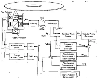
mmpmator . ~Figure 1. Block diagram of the conventional tine track-seeking scheme usine velocitv control
M c j c
+
B,X,
=
U ,
,
M F 2 F
= U , + B F ( &
- 2 , ) + K F ( X C
-xF),
(1)( 2 )
x,
=x,
- X D .
(3)Where Mc and Bc are inertia and damping element of the coarse actuator, MF,
BF,
andKF
are inertia, damping and spring element of the fine actuator. However, in conventional optical storage devices, the compensators for the two actuators are designed separately for simplicity. As shown in Figure 1, the tine actuator is controlled by the tine actuator compensator oniy and the coarse actuator controller is cascaded on top of the fine compensator. Accordingly, the disc eccentricity, X,, and the lens misalignment both become extemal disturbances to the fine actuator loop, where the lens misalignment means the displacement between the position of the fine actuator,X ,
and that of the coarse actuator, Xc. The lens misalignment comes due to the difference of bandwidth of the two actuators. Thus, a superior tine track-seeking scheme should eliminate the influence caused by the two extemal disturbances, namely, disc eccentricity and lens misalignment.
111. CONVENTIONAL FINE TRACK-SEEKING SCHEME Figure I is the block diagram of the conventional fine track- seeking scheme using lens kick with velocity control [6-91 and this structure is widely applied to the consumer optical disk drives. The output signals from the PD (photo detector) cells in the pickup are supplied to the PreAmp for generating the
TES (tracking error signal) and the RFRP (radio frequency ,.ripple) signal. According to the type of optical discs, the generation method of TES can be either DPD (differential phase detection), push-pull, DPP (differential push-pull), or 3- beam. The RFRP, also named as focus sum signal or track sum signal, is derived from the summing output of the PD cells in
the pickup, which detects the reflected main laser beam. When the spot of laser beam traversing the disc during the track-
seeking operation, TES and RFRP become modulated relative to the track crossing. The modulation of the RFRP is a sinusoidal waveform with 90' phase shift from the TES, which is a sinusoidal waveform, or a saw tooth waveform depending on the generation method. The TES and the RFRP are both supplied to a comparator circuit to generate the digitized TEZC (tracking error. zero cross) signal and digitized W Z C
(RFW zero cross) signal.
In Figure I, the residual track counter uses the TEZC and the RFZC as inputs and calculates the RTC (residual track count), which is the number o f remaining tracks from the current position to the destination. The RTC is then supplied to the velocity profile generator, which is generated by a look-up table. The velocity profile generator outputs velocity command, VELcMo, according to the RTC. The moving velocity between disc and laser spot, VELTRK. will be detected by a frequency-velocity conversion circuit using the TEZC and the RFZC. The velocity error, VELEnR, which is generated by the difference between the velocity command (VELcMo) and the detected moving velocity (VELTRK), will feed into the track-seeking compensator. Interested readers please refer to
[IO] for further detail. When the RTC becomes zero, the servo system switches to track-following, and the TRO is switched to the output of the track-following compensator, and the laser spot can pull-in to the target track.
One major problem of the conventional fine track-seeking scheme is the detection delay time. The frequency-velocity conversion circuit for the laser spot velocity measurement calculates an inverse number of the cycles of TEZC and RFZC and converts the inverse number to a relative velocity between the laser spot and disc. Thus, until the next TEZC or RFZC is available, there is no information at all on the velocity measurement. During this time, the control is affected by using the latest measured velocity. As a result, a detection delay time occurs in the velocity detection operation. Specifically, because the real velocity of the optical pickup vanes during the time period between two consecutive measurements, the velocity feedback value maybe way off Furthermore, as the velocity of the laser spot decreases, the detection delay time increases. In addition, the velocity control
is
largely affected by the extemal disturbances, like disc eccentricity and lens misalignment. For example, when the real velocity decreases excessively in a low-velocity region right before the pull in to the track-following operation, the laser spot may actually move in the opposite direction owing to the eccentric velocity from the disk eccentricity. In this case, either the seek time may increase or the track-seeking operation may fail. Moreover, the detection delay time also results in a steady state deviation of the final velocity from the desired velocity profile. If the final velocity is out of the reach of the track-following servo bandwidth when pulling in to the target track, the laser spot may not be positioned on the target track.384
: ~ ~ ~ ~ ~ ~ ~ .~ . ~ ~ ~~~ . ~ ~ ~ 2
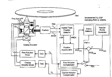
Figure 2. Block diagram o f the novel tine track-seeking scheme using HTP control
To deal with the above mentioned problems, this paper proposes
a
novel fine track-seeking scheme using a HTP (hybrid track position) detector. The HTP detector can measure the relative position between the laser spot and the target track. Using the output of the HTP detector for the feedback signal, the fine track-seeking control loop in Figure 2can precisely and stably control the moving velocity and the position of laser spot during the track-seeking operation. Especially when pulling in to the target track, the final moving velocity can be precisely maintained within the track-following servo bandwidth. Thus, the stability of the fine track-seeking operation and track-following servo loop can both he
guaranteed. The experimental results in the following sections will demonstrate its feasibility.
1V. A NOVEL FINE TRACY-SEEKING SCHEME The goal of a fine track-seeking servo in the optical storage devices is to achieve fast and stable access to data contained in a
target track. Thus, a fine track-seeking operation is always followed by a track-following operation for data read-out. In the sense of servo control strategy, the track-following control is to minimize the TES, which is inherently nonlinear and sinusoidal
(or saw-tooth). Therefore, it has a relatively narrow linear region.
If the TES is allowed a large value, the global stability of track- following control system may not he ensured. The most important requirement to guarantee stability in the track- following
control
is
to minimizethe
accessing velocity when pulling in to the destination track. This velocity also becomes the initial condition causing the overshoot in the transient response of the track-following control [ll]. If the overshoot exceeds the linear range of the TES, which is limited by the stmcme inherent to the optical instrument, Stability is no longer guaranteed. Therefore, the influence of the extemal disturbance, like disc eccentricity and the lens misalignment, must be rejected below an acceptable level. Notice that the moving velocity at the destination track depends on the disc eccentricity and is not controlled by the servo system whose bandwidth may reach2.4kHz for a tXS DVD.
lEEE Transactions on Consumer Electronics, Vol. 49, No. 2, MAY 2003 The proposed fine track-seeking scheme can he h l l y implemented by executing a program in a digital signal processor (DSP) without extra circuitry. This embodiment is suitable to a system-on-a-chip (SOC) design for the optical storage drive servo chip. In figure 2 , the fine track-seeking scheme is composed of a hybrid track position detector, a position accumulator, a position profile generator and a pull-in detector. The compensator of the track-seeking operation can use the same compensator of the track-following servo loop to simplify the design of system.
The HTP detector is a block for detecting a position change of the laser spot relative to the disc and the principle of the HTP detector will be detailed in the following section. The outputs of HTP detector, HTP and AREA, are supplied to the position accumulator, where HTP is a conversion output of the spot position relative to one track and AREA is an area changeover signal. By using AREA, the position accumulator in the HTP can detect both the occurrence of track crossing and the direction of moving. Therefore, the position accumulator can accumulate HTP and count the number of track crossing. The output of the position accumulator, POSHTP, subtracted by the position command, POScMo, then forms the required control feedback error, POSERR. The output of the position accumulator, POSHTP, is also output to the pull- in detector. When the laser spot reaches the vicinity of the target position, more precisely, 114 track to the target, the pull- in detector will change the state of the pull-in flag. The fine track-seeking is .switched to the track-following operation.
During the track-seeking operation, the input of the fine actuator compensator is POSEnn. When pulling in to the track- following mode, the input of the fine actuator compensator is switched to TES.
j Hybrid Track Posilion Dsledar
I ... ...
Figure 3. Block diaxram of the hybrid track position detector
The position profile generator is to generate the position command, POSCMD. The position command in turn comes from a well-defined velocity profile using proximate time
JLM. Huang and 1:Y. Yen: A Novel Fine Track-Seeking Scheme for Optical Stvrvge Device 385 optimal control theory. However, there is also a velocity limit
imposed by the bandwidth of the HTP detector.
Figure 3 is the block diagram of the HTP detector proposed in this paper. The HTP detector is composed of a TES offset controller, a RFRP offset controller, a TES peak detector, a RFRP peak detector, a TES offset detector, a RFRP offset detector, a TES gain calculator, a RFRP gain calculator, a TES
gain controller, a RFRP gain controller, a hybrid track position calculator and a register file. After focus sew0 is working stably, TES and RFRP become modulated due to the disc eccentricity. Then, the TES peak detector and RFRF' peak detector measure the maximum value and minimum value of TES and RFRP, TES offset detector and RFRP offset detector measure the offset value of TES and RFRP. The output of the TES offset detector, TESOFFSET, is supplied to the TES offset controller for removing the offset component of the TES. Similarly, the output of the RFRP offset detector, RFRPoFFsEr,
is supplied to the RFRP offset controller for removing the offset component of the RFRP. Accordingly, the outputs of the TES offset controller and the RFRP offset controller are offset-free signals.
The outputs of the TES peak detector and the RFRF' peak detector, TESuAx, TESMIN, RFRPMm, RFRPMIN, are supplied to the TES gain calculator and the RFRP gain calculator together with TESoFFsET and RFWOFFSET. Then, the TES gain calculator can calculate the gain value for normalizing the TES to tit a pre-determined range and output the gain value to the TES gain controller. Similarly, the RFRP signal can be normalized by the RFRP gain controller and the W R P gain calculator. The normalized TES and RFRP, T E S N o n ~ and RFRPNOnM, are supplied to the hybrid track position calculator. The registers tile stores the parameters needed in the HTP calculator.
TABLE I
CALCULATION OF TUB HYRRID TRACK POSITION Area Transformation Formulas Range
I HTP = HTP4 - (TESNORMiLcvel3) x [HTP3,HTP4] 2 HTP = HTP2 - (RFRPNORMiLevellN) x [HTPZ,HTP3] (HTP4 ~ HTP3) (HTP3 - HTP2) 3 HTP ~~ = HTPZ ~~ - (RFRPNORMiLevell Pi x IHTPI.HTPZ1 (HTPZ - HTPI)
4 HTP = (TESNORM/LrvelZ) x (HTPI) [O,HTPI] ''
5 HTP = (TESNORM/Level2) x (HTPI) [-HTPl,O]
6 HTP = -HTP2
+
(RFRPNORMiLevellP) x [-HTP2,-HTPI] 7 HTP = -HTP2+
(RERPNORM/LevellNi x I-HTP3:HTPZI (HTP2 - HTPI) , . ~~ (HTP3 ~ HTP2) 8 HTP = -HTP4 - (TESNORM/Lcvel3i x I-HTP4,-HTP31 (HTP4 - HTP3)-
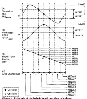
Figure 4 shows an example of the HTP calculator by using DPD TES and RFRP in a case where a relative position between the track and laser spot changes at a predetermined rate. Figure 4(a) is the normalized TES ( T E S N O ~ ) , Figure 4(b) is the normalized RFRP (RFRPNOnM), Figure 4(c) is the linearization position (HTP), and Figure 4(d) is the associated
area changeover. As evident from Figure 4(a) and Figure 4(b), TES i s a saw tooth wave and RFRP is a sine wave signal, both TES and RFRP include some linear regions and some nonlinear regions. More precisely, when RFRP is nonlinear, the corresponding TES is linear or quasi-linear. Similarly, when TES is nonlinear, the corresponding RFRP is linear or quasi-linear. Based on this phenomenon, HTP can be generated by using RFRP or TES depending on which one is linear. Obviously, in area 1, 4, 5 , 8, TES is linear or quasi- linear to HTP, HTP can he calculated by using TES only; in area 2, 3, 6, 7, JWRP is linear or quasi-linear to HTP, HTP can be calculated by using RFRP. Accordingly, HTP is calculated based on Table 1 ... I , * (a) TE%ORM Normalized I , , !
I
, TES ....,... * ... * ... ... ... Level3 LeYellP LevellN (C) Hybdd Track Position HTP , ... j OnTrack ~ j 0 OhTrack jFigure 4. Principle of the hybrid track posilion calculator > ... _,
V. SYSTEM CONFIGURATION AND COMPENSATOR DESIGN
Figure 2 depicts the block diagram of the proposed digital control system. The main processor in the experiment is a single-core 32-bit microcontroller-DSP type of Infineon TriCore, which is optimized for real-time embedded system. Sensor signals are filtered to remove high frequency noise and converted to digital value by on-cbip 10-bit
AID
converters. Control inputs calculated by DSP are converted by on-chip 10- bit D/A converters. Moreover, the sampling rateof
the proposed fine track-seeking scheme is 100 kHz so that the max detectable velocity of HTP detector is limited to 35tracksimsec. Besides, both TES and RFRP are filtered by low pass filters for eliminating the high frequency noise, so the bandwidth of TES and RFRP are also restricted within 40 kHz. Accordingly, for stable operation of the proposed scheme, the max detectable velocity is set to 3 5 W z and the max velocity command should be limited within 30Wz.386
Based on the concept of the fine track-seeking scheme proposed in this paper, the compensator of the track-seeking can share the same controller as the track-following servo loop as shown in Figure 2. This is because both the track-seeking loop and the track-following loop are position feedback loops. Accordingly, the compensator design should follow the instruction of DVD hook ("DVD Specification for Read-Only Disc"), the bandwidth of open loop transfer function (a series connection of compensator and plant) should he kept above i.4kHz for IXS DVD. Actually, the rotation speed of the spindle motor proposed in this paper is CAV (constant angular velocity)
ZXS,
so the bandwidth of open loop transfer function should be, even higher than 2.41dIz experientially. As a result, if the sampling rate of the compensator is 100!
&
z
,
the coefficients of a lead-lag compensator are chosen to be:IEEE Transactions on Consumer Electronics, Vol. 49, No. 2, MAY 2003 lens position misalignment. The conventional lens kick using velocity control is strongly affected by the extemal disturbance, and the final velocity cannot always converge to the control bandwidth of track-following servo loop. Notice that we 'always design a proximate time optimal velocity profile under rugged consideration. Therefore, a more efficient velocity profile leads to better seek time and a more reliable system.
Figure 7 and Table 3 show the experimental result of five continuous 7 tracks'seek with the tine track-seeking. The test disc is also ABEX TDR-813 DVD-ROM. Figure 7(a),'(c) and (e) are the resultant signals from the proposed
HTP
control scheme. Figure 7(b) and (d) are the results from the conventional lens kick scheme using velocity control. These experiment now show the performance of fine track-seek scheme against the disc eccentricity when the accessing distance is small. In some application, like DVD video playback, this test is vely important. In DVD Video disc, the Mpeg2 stream and subtitle are located on different neighboring tracks. The optical drives need to access the mpeg2 stream and the selected subtitle back and forth by continuously repeating the fine track-seek operation. If anyone of the repeated fine track-seeking fails, the video, playback will be delayed, resulting in frozen pictures. From the curves in Figure 7 and Table 3 , the proposed scheme demonstrates much better velocity control ability and better reliabilitL agaln..
~ ~. VeloCitY Control..
, '.
(4) 1 - 0.94842-' - 0.9987z-'+
0.94982-' 1-1.228Oz-' +0.1294z~'+0.10022~' C(z) = 26 x 0. I456 xThe frequency response of the compensator Is shown in Figure 5. The phase
of
the lead-lag compensator at3kHz
is about 60' that provides a large phase margin for the close loop system.I
Frw iHiiI
Figure 5. Frequency response of the fine actuator campensstor
VI. EXPERIMENTAL RESULTS
Figure 6 shows the experimental results of five continuous
255 tracks of fine track-seeking. The test runs on an ABEX TDR-813 DVD-ROM test disc with 15Opm eccentricity. Figure 6(a), (c) and (e) are the resultant signals from the proposed HTP control scheme. Figure 6(b) and (d) are the results from the conventional lens kick scheme using velocity control. The experimental data is also compared in Table 2. It
is clearly. seen that the performance of the proposed HTP control scheme is superior to that of the conventional servo. The proposed
HTP
control scheme provides shorter seek time, more eficient velocity profile, better reliability, more accurate final velocity control, and more stable pull-in condition. The 4 curves in the experiment is to compare the control ability against the extemal disturbances, like disc eccentricity and'3 2m 1cO 0 n Id1 20 10 0 10 20 loa
"G
v s 0 9 9 5 10 105 11 1 1 5 ,,me I"/ .. Figure 6. Experimental iesults of 255 traclisof kine track-&ekingTABLE 2
EXPERIMENTAL DATA OF 255 TRACKS OF FINE TRACK-SEEKING
Item HTP Control Velocity Control
Max. seek time 10.5637 [msec] 25.2920 [msec] Min. seek time 10.5581 [msec] 19.1400 [msec]
Avg. seek time 10.5604 [msec] 23.0056 [msec]
J:M. Huang and 1.-Y. Yen: A Novel Fine Trrack-Seeking Scheme for Optical Storage Device 387 01 Veloclll Control 6 1 2 6 4 2 0 0 5 1 1 5 tame I”] ....
.
~Fig&
i.
Experimental results i f 7 i r a e g o f fine track-seeking TARI.P.I. ...-EXPERIMENTAI. DATA OF 7 TRACKS OF FINE TRACK-SEEKING
Item HTP Control Velocity Control
Max. seek time 1.2751 [msec] 1.6200 [msec] Min. seek time 1.2670 [msec] 1.2600 [msec] Avg. seek time 1.2701 [msec] 1.4802 [msec] Max peak velocity 8.5188 [tracksimsec] 6.9098 [tracksimsec] Min peak velocity 8.2937 [tracksimsec] 5.2341 [tracksimsec] M a x final velocity 2.2246 [tracksimsec] 6.4361 [tracksimsec] Min final velocity 2.1024 [tracksimsec] 3.9276 [tracksimsec]
VII. CONCLUSION
This paper proposed a novel fine track-seeking scheme using a new hybrid track position detector. The proposed HTP detector and the position accumulator enable a linear position measurement over a wide range of accessing travel. The fine track-seeking scheme is then designed based upon the HTP position infomiation. Because both the track-following servo and the fine track-seeking servo are position feedback systems, the two servo loops share the same compensator. The result is a simplified tuning process in the system integration phase. The experimental results show that the pioposed scheme achieves very accurate position control, better seek time performance, more reliable operations and better velocity control perfoimance. The final velocity control
is
especially efiicient. This final velocity control performance also assures successful pull-in to track-following operation. In addition, the fine track-seeking experiment demonstrates the ability of the proposed scheme against the external disturbances, like disc eccentricity and lens position misalignment.REFERENCES
J. McCormick and R. Horowitz, “Time optimal seek trajectories for a dual stage optical disk drive achmtor”, Transactions of ASME, vol. 113, pp. 534-536, 1991.
J . D. Yang and X. D. Pei, “Seek time and trajectories of time optimal control for a dual stage optical disk drive achlator”, E E E Transactions on Magnetics, vol. 32, no. 5 , pp. 3857.3859, 1996.
J. D. Yang and X. D. Pan, ‘Time optimal seek control for a coupled dual stage disk drive actuator”, IEEE Transactions on Magnetics, \‘ol. 33, no. 5 , pp. 2629.1970, 1997.
K. B. Jin, T. Y . Doh, J. R. Ryoo, and M. J. Chung, “Robust direct seek control for high-speed rotational optical disk drives”, IEEE Transactions on Consumer Electronics, vol. 44, no. 4, pp. 1273-1283, 1998. K. B. lin, H. K. Lee, and M. 1. Chung, “Direct seek control scheme for
high-speed rotational optical disk drives”, Electronics Letters, vol. 34, no. 15,pp. 1476-1477, 1998.
Tamane Takahara and Akihiro Kasahara, “Optical disk tracking system for searching a target track based on a table of compensation reference velocity”, United States Patent 5566148, 1996.
Taamane Takahara and Akihiro Kasahara, “Optical disc apparatus with accessing using only reference velocity during acceleration and reference and moving velocities during deceleration”, United States Chih-Hsien b o , Sheng-Yuno Wang, “Control device of a pickup head for locating the track position”, United State Patent 6154424, 2000. R. R. lung, K. B. ling, T. D. Doh, M. J. Chung, “New fine seek control for mtieal disk drives”. Proceedine of the Amencan Control patent 5497360, 1996.
Confc;ence, vol. 5 , pp. 3635-3639, 1999’ system“, United States Patent 5796686, 1998.
optical disk drive system”, United States Patent 6320828,2001. [IO] Satoru Maeda, “Track jump control apparatus for disc reproducing [I I] Kai C. K. Sun, “Servo systeh having track crossing detectio? for an
Ja-Ming Huang was bom in Taipei,Taiwan, Republic of China, on October 21, 1973. He rec+ved his B.S.,depe and Ph.D. in Mechanical Engineering in 1995 and 1999 from the National Taiwan Univmily, Taipei, Taiwan. He joined the Gp&ElecUonics and Systems Laboratories (OES), mU as a research mgjneer since
1999. His research interests include maglev system design and
s e n 0 system of optical storage devices.
Jia-Yish Yen (M’87) became a member of IEEE in 1987. He was bom in Taipei, Taiwan. He received the B.S. degree in mechanical engineering from Natignal Tsinghua University, Hsinchu, Taiwan in 1980, and the M.S. degree from University of Minnesota, MN, in 1983. In 1989 he received the Ph.D. degree in mechdnicd engineering from University of Califomia, Berkeley, CA. During his study at Berkeley, he received the lBM Fraduatb Fellowship in 1984-1955. Since 1989, he has been with National Taiwan University, Taipei, Taiwan, where he is currently 8 Professor of Mechanical Engineering. He served as the treasurer of the
Control System Chapter in IEEE Taipei Section in 1992. He also served as consultant for many companies including Industrial Technology Research Institute, Taiwan and C Sun MFG. LTD., Taiwan. His research interests are in the areas of modeling and control ofelectromechanical systems, especially in precision control of computer peripherals and precision measurement systems. He is also a member afthe ASME.