A New Fault Location Algorithm for Series Compensated Lines Using Synchronized
Phasor Measurements
Chi-Shan
Yu**
Chih-WenLiu*
Joe-Air Jiang****
**
*+* Depmment of Electrical Engineering. Private Kuan-Wu lnstitiite of Technology and Commerce. Taipei. Taiwan
Department of Electrical Engineering. National Taiwan University, Taipei. Taiwan
Department of Electrical Engineering National Taiwan University. Taipei. Taiwan. and Department of Electrical Engineering, Private Kuan-WU Institute of Technology and Commerce, Taipei. Taiwan
Abstract: In this paper. a novel fault location algorithm based on phasor measurement units
(PMUs)
for series compensated lines ;has been proposed Traditionally, the voltage drop of series device lhas always been predicted by the device model in the fault locator of series compensated lines. but some of the errors are induced from the inaccuracy of the series device model or from the uncertainty of the protection function of series device. The proposed algorithm does inot need the series device model and information of the protection hnction of series device to predict the voltage drop. Instead, two iteration steps, pre-location step and correction step. are used in >the proposed algorithm to calculate the voltage drop and fault location. Thus. the more accurate fault location for series compensated lines can be achieved. The proposed technique can be easily applied to any series FACTS system. The accuracy of the fault location algorithm1 istested by the EMTP generated data with respect to a 300km 345 ItV transmission line under different fault locations. fault resistances and fault inception angles. The results show the high accuracy up to 99
WO.
Keywords: series compensation, synchronized phasor measurement units. FACTS.
I .
INTRODUCTION
In the last two decades, the power electronic applications to AC power systems have provided many benefits. Applying series compensation in power systems can increase power transfer capability. improve transient stability and damp power oscillations. However, since the variation of series compensation voltage remains uncertain during the fault period, the protection of power systems with series compensated lines
is
considered as one of the most difficult tasks and is an important subject of investigation for relay manufacturers and utility engineers.Series compensated systems can be mainly catalogued into switched capacitors (SCs) systems and thyristor controlled switched capacitors (TCSCs) [2.3] systems. Typically. the main problem in designing series capacitors protection systems is over-voltage
protection of the capacitor itself. Since the nonlinear devices of MOV [ 1 J and TCR incorporate with their protection hnction [4] introduce in series compensation devices. the voltage drop of the series device
IS not easily calculated. Recently, some studies associated with the
analysis of simplified series device models have been proposed in [S-71 and all produce satisfactory results. However, these algorithms must consider the model of series device to compute voltage drop arid the model considered in those papers are simplified. Thus. the accuracy of those papers is limited.
The synchronized PMUs based fault detector/locator technique has been proven effective for fault relaying of transmission line without series compensation device [8- IO]. However. when the series compensation device is installed in the transmission line, the previous proposed technique [8-10] must be incorporated with the series device
model to estimate voltage drop of series device in fault location Computation.
This paper proposes a new approach, only considering synchronous measurement data from both ends of the transmission line, to estimate fault location of a series-compensated transmission line. The proposed algorithm excludes voltage drop calculation of the series compensation device. Instead, two-iteration step, pre-location and correction steps are used to calculate voltage drop and estimate fault location. This simplifies precise fault location estimation. Besides, since this algo&hm does not use the series device mode, the proposed fault locator is easier to design and implementation.
When the series compensation device is installed in the transmission line. the fault locator must decide the correct fault side with respect to the series compensation device. In this paper, a skillful fault side selector is presented.
The rest of this paper is organized as follows. Section I1 begins by describing the theory utilized to determine the fault location of a TCSC-compensated, short single-phase transmission line. whose capacitance charging effect is ignored. The proposed fault location technique is then extended into a two-step fault location algorithm for cases involving transmission line shunt capacitors. Furthermore. this section proposes
a
skillful selector for selecting the correct faulted sides with respect to series compensation device. Next, Section I11 uses a 345 kV sample system i to evaluate the accuracy of the proposed algorithms with respect to different fault types, fault locations, and fault resistance. These simulation results come from extensive EMTP [I41 tested case. Conclusions are finally made in Section IV..11. PRINCIPLES
The proposed algorithm is derived using the following assumptions:
I the fault impedance is pure resistance. 2. the fault type is known.
The assumptions above are common in the literature dealing with the fault location issue.
The basic principle of the proposed algorithm is first illustrated via a simple single-phase case and is then extended to the case of a three-phase traramission line with shunt capacitance.
SINGLE PHASE
-
Illustrative CaseTo illustrate the basic idea of the proposed algorithms. this work first considers tlhe single-phase series compensated line represented in Fig. I It considers the line as a short distance transmission line, that is, it ignores the shunt capacitance o f t h e line. The series compensation device is installled at a distance of q [P.u.] away fiom the receiving end of the considered line.
First, the fault is assumed to be located on the right side of the series compens:ation device. According to Fig.3, the midway fault occurs at point I? which is Y = DRL (km) away from the receiving end R of transmission line
SR.
The total length of the transmission line isL kilometers. m d DR (P.u.) is the per unit distance from receiving end
to fault location. When a fault occurs at point F, the transmission line
Since the fault location with respect to the series compensation device is unknown prior to fault location estimation. the proposed fault location algorithm will first calculate two locations via subroutines 1 and 2 simultaneously. These two faults are assumed to occur at right and left-hand sides of the series device, respectively.
L c f l H d RighlHnnd Side + + Side
Rnriving End
Sending End
Then, this paper presents a skillful selector for exactly distinguishing the true fault site. The following subsection explains this skillful
,
+ Compensation
9 T
.I
selector.
Subroutine I
-
Fault location for the right side of theE, v, bits .f:Vp
-&
-
-.- .
4 DL series compensation device
I
L qL
4 The description of subroutine 1 is divided between the pre-location
and correction steps. is divided in two line sections. One is line section SF, while the other
is line section RF.
Using the assumption 1, it is easy to obtain that the phase relationship at point F can be expressed as:
where the Arg( ) represents the phase angle.
Since the ground fault occurs on the right-hand side of the series compensation device, the line section RF can still be regarded as a perfect transmission line (no series device). Thus, the voitage at any point on the line section
RF
(including the fault end point) can be easily solved by KVL, i.e.where ZL is the total impedance of the considered line, and DR is the per-unit value of the fault location.
Additionally, the currents Iw at line section FR and ISF at line section
SF
also equal the currents measured on receiving and sending ends (ignored shunt capacitance), respectively. Thus, the fault currentIF = IWfIsF can also be obtained as:
"%(vF)=&dIF) (1)
V F = VR
-
IRDRZL'Re{VF}+Jrm(VF} (2)IF"
+
ISF = IS f IR=Re{ IF)+jIm{ IF) (3)
Therefore, the measured data
(Vs,
Is) and (V, IR) and (1) can be used to calculate the VF and IF, i.e., by substituting (2) and (3) into (I), givingRe{VF}xlm{IF}=Re{IF}x~m{VF} (4)
Notably. the only unknown variable in the above equation is the per-unit distance DR. The series device model is not used in deriving (4). Therefore, the per-unit fault location
DR
is easily calculated and the series compensation device model is not needed.THREE-PHASE CASE
-
with Shunt CaDacitanceSince this case considers the shunt capacitance of the line, the currents Iw and IsF entering the fault point F, as indicated in Fig.3, will not equal the currents TR and Is as measured at the receiving and sending ends, respectively. The distributed model of the long distance transmission line can be used to calculate these currents. However, the current ISF can't be calculated with the transmission line model, since the voltage on the right-hand side of series compensated device is unknown. Thus, the relation of (3) is difficult to achieve and the proposed algorithm cannot be directly applied in this case.
Applying the idea mentioned above to a three-phase transmission line with shunt capacitance, the proposed fault location algorithm must be modified and extended to a two-step algorithm
-
the pre-location and correction steps. The pre-location step is to calculate feasible initial fault location, providing an initial value close to the correct fault location. Then, the correction algorithm is applied to calculate the correct fault location. meaning the model of the series compensated device is still not needed.Pre-location SteD
The basic concept in the simple illustrative cases is extended and modified to become the pre-location step. This study discusses the pre-location algorithm using three phase shorted fault case. For other types of fault, the following procedures can be easily extended.
1 . Three phase shorted fault case:
Herein, we only use the positive sequence component. The equations of fault voltage and fault current on the fault location x = DR can be expressed as follows [13]:
vF= VFI
exp(-ylDRL)
' R I-
RI%exp(ylDRL)
4- 'RI + I R l z C l-
-
2 =Re{vFi} + J I ~ { V F I1
( 5 ) IF =IF1 =IRFI+ISFI = Re{IFI} +jIm{IFI} ( 6 ) '%(vFI)=&(IFI) ( 7 )Thus, the relation of (1) can be rewritten as
Using the same treatment with single-phase case, the per-unit initial fault location DR can then be easily calculated by the following equation:
(8)
1
'Im{ IF1 }=Re{ IF11
Im{ VFI 1Correction SteD
Since the right-hand side voltage VsER of the series compensated device in Fig.1 is unknown (that is, the voltage drop of series compensated device is unknown), the shunt charging current between the series compensated device and the fault end point is also unknown. Thus, when the proposed fault location algorithm is directly applied to transmission line with shunt capacitance, the main error will be
I
-
. ....
0 t .-
L D L DNiee , 4 4 ---_?induced from the unknown voltage drop of series compensation device. This subsection proposes a novel correction algorithm to adjust the pre-location result to a correct solution. Meanwhile, the voltage drop of the series compensation device also can be calculated. Since the new unknown variable of VSm is introduced in long distance lines, there need another new equation other than that used
in
pre-location step to calculate the new variable. Fig.2 indicates that the transmission line between series device and the fault point is modeled as a two-port hyperbolic x-model between the fault location end arid the series compensated device right-hand side, i.e.ZE=Z, sinh( y
I>
Y/2=1/Zc tanh( y 1 /2) (5')
where I = (q
-
Do)L (km) is the line length of the x-modlel transmission line.Since the series compensation device does not influence the current flowing through it. the current IsEL flow into the left-hand side of series device will equal the current IsER flow out from the right-hand side of the series device. Thus, the two-port circuit enclosed by dashed line has two input parameters, one is the correct input current
ISER and the other is the voltage VFo computed from the pre-location
step. The basic circuit theory indicates that the input voltage V S U ~ ~ (the second iterative value) of the two-port circuit can be easily calculated as
V S E R F Z E ~ 1 +Y/~xZE)(ISER+VF~ZE) (10) Therefore, a new fault location problem can be constructed. The transmission line being considered is located between the two terminals of (VSER,, ISER), (VR, IR), enclosed by the dotted line in Fig.2. The line length of the new system is
qL
(km) and tbe transmission line between these two terminals has no series compensated devices.Vs=VsERI, IS=ISER can be substituted into the pre-location algorithm proposed in previous subsection to calculate a new fault location
D,
and fault end voltage VFI. These two parameters allow the third iterative value of voltage VSERn (i.e. VSER2) to be once again computed from the iterative formulae (9) and (IO). The proposed algorithm will repeat the procedure until faultD
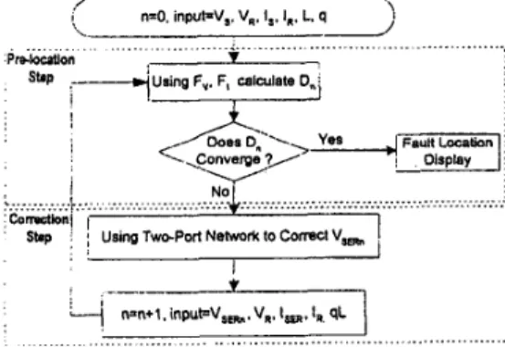
is accurately located. This investigation reveals that the proposed algorithm usually takes 3-4 iterations to accurately locate a fault. Thus, the fault location for a series compensated transmission line is straightforward using the proposed algorithm and the device model is still not required. The flowchart in Fig.3 depicts the pre-locatiodcorrection two-step algorithm.Subroutine 2- Fault location for the left side of the series compensation device
When the fault occurs on the left side of the series devices, the reference point on x = L can be deliberately changed, substituting the
/
I n=O. inputpv,. v,. Is. 11, L. q
x,
2 ... ,prolocouo." l.-- <.. ... .A Sbp ;+using F,. F, calculate 0,: T+-;;-\
...Fie.3 Flow-chart of two-stem fault location aleorithm
following relationships:
into the above two-step iterative formulae, and thus obtaining a new per-unit fault location (denoted as
D'
) in relation to the reference x = L. When x = 13 is taken as the reference point, the final per-unit fault location can be computed from DL = I - D' .V~=VR, V~='t's, Is=
-
I R and IR=-
1s ( 1 1)FAULT SELECTOR
For systematically selecting the true fault location this subsection proposes a skililful selection algorithm. The proposed two-step fault location algorithm can calculate the voltage of VsER in Fig.2. Additionally, the voltage VSEL of the point just in front of the series device is also easily calculated from the transmission line equation. Thus, the voltage drop
AV,,
of the series compensation device can be calculated by Vsu-VsER. The equivalent impedance of the series compensation device can be calculated as' S
E = "SE /ISER = RSE + jzSE (12)
If the estimated result of the fault location is on the correct side, the RSE will be a positive value (obeying the law of physics). Otherwise, the Rs, will be negative (violating the law of physics) for the incorrect side estimation. For example, when b-c line-to-line fault occurs on the right side of the series device, the RSER of b-phase and c-phase calculated from subroutine 1 will be positive. Otherwise, when using subroutine 2, the calculated RsEL of the b and c-phases will be negative. Thus, the selecting criteria can be stated as:
The fault location of the estimated set
[DR,
DL]
that corresponds to positive RSe is selected as the correct solution.111. PERFORMANCE EVALUATION
ALGORITHM TEST
This subsection evaluates the fault location algorithms proposed here using somc: case studies. The simulation sample considered is a 300km. 345kV .transmission line compensated by thyristor controlled switched capacitance (TCSC) with a compensation degree of 70%. All the systems are modeled by
EMTP.
The phasors are estimated using the SDFT [11,12] filtering algorithm working at 32 samples per cycle. The total simulation time is 200 milliseconds and the error of the fault location is expressed in terms of percentage of total line length. Appendix A presents the parameters of the sample system. As is well known, the different protection function design of TCSC will introduce different type of disturbances into compensation voltage. Thus, the protection functions of TCSC must be considered when evaluating the performance of the proposed fault location algorithm. For convenienci:, this investigation adapts the protection hnctions presented in [4].Table I. Parameters of the simulation system System voltage 345kV
EF I .O L O'pu
&.AI= 1.3 I+j 1 5( R )
Zs~E2.33+j26.6( R ) Zse0=2.33+j26.6( R ) Transmission linse parameter : length=300km
Positive sequence:R=O.O27S( Q/km) L=0.836(mH/km) C=0.038(uFkm) Zero sequence : R=0.275( Rkm) L=2.7233(mWkm) C=O.O38(uFkm) MOV : I w ~ l k A , V e l 4 0 k V , Exponent=23, Ratted enerp5MJ
System frequency 60Hz ER=^ .O L
-
1 O'puZSBI= I .3 1 +j I S( R )
Case Study: Large Fault Current IF Cases
In this case, the TCSC device is installed near the midpoint at 135km (q = 0.4.5 P.u.) away from the receiving end of the protected
I I
3
i'/
I t I , I t t. : I : 0.481 I :
2 25 3 3.5 4 4.5 5 5.5 6 post-falt cyde (cyde)
Fig.5 Fault Location Calculation by SDFT (solid line) and DFT (dotted line)
Fault occurs at O.lsec
@j" * -_._.
__
;MOVsCurrent I iI
2 , I 0.08 0.09 0.1 0.11 0.12 0.13 0.14 0.15 Time (sec)line. Assume that a three-phase ground fault occurs at 150km (D = 0.5 P.u.). The fault resistance is set as 1 (Ohm).
The fault locations D, and DL are computed from subroutines one and two simultaneously. Meanwhile, Fig.6 plots the estimations of DR
and DL. At 2.5 cycles after fault inception, the proposed algorithms provide the following results:
Fig.6 The Waveform of TCSC
DR=
0.3682 (P.u.),DL=
0.50008 (P.u.)Obviously, the two-step iteration algorithms can provide accurate fault location in this case. The equivalent resistance of RSEL and RSER also show9 in Fig.4(a) and Fig..l(b) respectively. Notably, that the RsER is negative. Therefore, one can easily choose D=DL=0.50008
as
the correct solutionFig.5 compares fault location calculation using DFT and SDFT [ 13- 161 filters. Obviously, the exponential decay of DC-offset' in the fault current and voltage signals will markedly influence fault location when fault location is calculated by DFT. When the fault location result is calculated using SDFT, then the calculated location would not have the same slow damping as in the DFT results. Instead, the calculated fault location converges very fast and an accurate location is easily and quickly achieved.
Fig.6 presents the detailed waveform of the TCSC before and &er
a fault occurs. The TCR switches to the block mode and the MOV
begins to bypass the fault current WhGn thG fault starts to occur at FTl, since the over-voltage condition is detected by the TCSC controller.
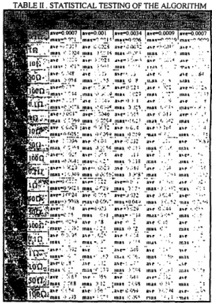
TABLE 11. STATISTICAL TESTING OF THE ALGORITHM
The TCR changes to bypass mode at t =
Tz,
since the energy absorbs in theMOV
is exceed its limitation. Notably, the proposed algorithm can still easily provide the accurate fault location result, whatever the complexity of the TCSC protection function operates.STATISTICAL EVALUATION
This subsection evaluates the proposed fault location algorithm with over 500 test cases obtained from the
EMTP
simulator. It considers different fault types, resistances, locations, and inception angles as statistical tests. It uses the same transmission line and series compensation device data as the previous subsection. Table I summarizes all of these results. To save space, all of the fault location errors are calculated as the average value of five inception angles (0, 45, 90, 135, and 180 degrees in relation to the zero cross of-a-phase voltage). In this table, variable ave is the average fault location with respect to-five inception angles. For comparison, variable max is the maximum fault location error in five inception angles. Generally, the maximum error is 0.27% and the average error is about 0.034%. The error increases in large fault resistance cases. Additionally, if only the normal fault resistance is considered (smaller and equal IO Ohm [7]), the maximum error can be reduced to 0.12% and the average error is only 0.0 182%.IV
.
CONCLUSIONThis work has successhlly proposed a novel fault location algorithm for series compensated lines. The proposed algorithm does not utilize the series device model and knowlMge of the operation mode of series device to compute the voltage drop during fault.. Thus,
the fault location errors induced from incorrect .series compensation
device model or inaccurate modeling of the series'-device protection hnction model can be eliminated completely. Furthermore, because
the fault locator designer does not need the series compensation device model to design the fault locator, designing the proposed fault locator becomes easier than in conventional designing. Additionally, the proposed fault location algorithm can be easily applied to any other series compensated line that has no additional shunt branch or phase shift contribution on line current. To select the correct fault location with respect to the series device, this work has presented one skillful selector. The simulation results show the proposed fault location algorithm is useful and easily produces accurate fault location result.
V .
REFERENCE
Goldswortyh
D.L.,
“A linearized model for MOV-protected series capacitors”, IEEE Transactions on Power Systems, V01.2,No.4, November 1987, pp.953-958.
Christ1
N.,
HedlnR.,
Johnson R., Krause P. and Montoya A., “Power system studies and modeling for the kayenta 230KV substation advanced series compensation”, IEE International Conference, 1991, pp.33-37.Urbanek J., Piwko R.J., Damsky
B.L.,
FurumasuB.C.
and Mittlestadt W., “Thyristor controlled series compensation prototype installation at the slatt 500KV substation”, IEEE Transactions on Power Delivety, Vo1.8, No.3, July 1993,Tanaka Y., Taniguchi H., Egawa
M.,
FujitaH.,
Watanabe M.and Konishi
H.,
“Using a miniature model and EMTP simulations to evaluate new methods to control and protect a thyristor-controlled series compensator”, IEEE Winter Meeting1999.
Novosel D., Bachmann B.,
Hu
Y. and Saha M.M., “Algorithm for location faults on series compensated lines using neural network and deterministic methods”, ZEEE Transactions onPower Delivery, Vol.11, No.4, October 1996, pp.1728-1736. Saha M.M, Izykowski I., Rosolowski E. and Kasztenny B., “A new accurate fault locating algorithm for series compensated lines”, IEEE Transactions on
Power
Delivery, Vol.14, No.3,Girgis A.A., Satlam A.A. and El-Din A. Karim, “An adaptive protection scheme for advanced series compensated (ASC) transmission lines”, IEEE Transactions on Power Delivery,
Vo1.13, No.2, April 1998, pp.414-420.
Kezunovic M., Mrlic J. and Pemnicic B., “An accurate fault
location algorithm using synchronized sampling”, Electric Power Systems Research, Vo1.2, 1994, pp.161-169.
Jiang J.A., Yang J.Z., Lin Y.H., Liu C.W. and Ma J.C., “An adaptive PMU based fault detection/location technique for transmission lines,
Part
I: Theory and algorithms”, accepted by IEEE Transactions on Power Delivery.Jiang J.A., Lin Y.H.. Yang J.Z.,
Too
T.M. and Liu C.W., “An adaptive PMU based fault detectiodlocation technique for transmission lines,Part
11: PMU implementation and performance evaluation”, accepted by IEEE Transactions on Power Delivery.Yang J.Z., Liu C.W., “A precise calculation of power system frequency and phasor”, accept by IEEE Transactions on Power Delivery.
Yang
J.Z.,
Liu C.W., “Complete Elimination of DC offset in current signals for relaying applications”, accepted by IEEE Winter Meeting, 2000.Gross C.A., Power System Analysis, John Willey, 1986. Dommel H., Electromagnetic Transient Program, BPA,
Portland, Oregon, 1986. pp. 1460-1469.
July 1999, pp.789-797.
VI.
BIOGRAPHIES
Chi-Shan
Yu
was born in Taipei, Taiwan in 1966. He received his B.S. and M.S. degree in electrical engineering from National TsingHua
University in 1988 and 1990, respectively. Since 1991, he has been with Private Kuang-Wu Institute of Technology and Commerce, where he is an instructor of electrical engineering. He is a candidate for the Ph.D. degree in the electrical engineer department at National Taiwan University. His current research interests are computer relaying and transient stability control.Chih-Wen
Li,g
was born in Taiwan in 1964. He received the B.S. degree in Electrical Engineering from National Taiwan University in 1987, and M.S. and Ph.D. degrees in electrical engineering from Cornell University in 1992 and 1994. Since 1994, he has been with National Taiwan University, where he is associate professor of electrical engineering. Heis
a
member of the IEEE and serves as a reviewer for IEEE Transactions on Circuits andSystems, Part I. His main research area is in application of computer technology to power system monitoring, operation, protection and control. His other research interests include GPS time transfer and chaotic dynamics and their application to system problems.
EM-wave.
Joe-Air Jiang was born in Taipei, in 1963. He graduated