ically differentiated by a UWB antenna (circle type line). We can find that the PSD of the measured pulse after differentiated by the antenna is under the FCC spectral mask.
4. CONCLUSION
We have designed, fabricated and tested the proposed pulse gen-erator. The complete circuit is designed and fabricated in a stan-dard TSMC 0.18-m CMOS technology. Our proposed pulse generator has many advantages including a good symmetry, low-ringing, and a wide bandwidth characteristics. The output pulse approximates a higher-order derivative Gaussian pulse with a pulse duration of 500 ps and a 40 mV amplitude. The power consumption of the pulse generator is about 18 mW.
ACKNOWLEDGMENTS
This research was supported in part by a grant of making chips from National Chip Implementation Center (CIC), Taiwan.
REFERENCES
1. IEEE 802.15 WPAN high rate alternative PHY task group 3a (TG3a). Available at http://www.ieee802.org/15/pub/TG3a.html.
2. M.Z. Win and R.A. Scholtz, Impulse radio: How it works, IEEE Commun Lett 2 (1998), 36 –38.
3. S. Roy, J.R. Foerster, V.S. Somayazulu, and D.G. Leeper, Ultrawide-band radio design: The promise of high-speed, short-range wireless connectivity, Proc IEEE 92 (2004), 295–311.
4. Federal Communications Commission, Revision of part I5 of the commission’s rules regarding ultra-wideband transmission, ET Docket 98 –153, Federal Communications Commission, April, 2002. 5. J. Han and C. Nguyen, A new ultra-wideband, ultra-short monocycle
pulse generator with reduced ringing, IEEE Microwave Wireless Com-pon Lett 12 (2002), 206 –208.
6. H. Kim, D. Park, and Y. Joo, Design of CMOS Scholtz’s monocycle pulse generator, In Proceeding of the IEEE Conference on UWB Systems and Technologies, 2003.
7. S. Bagga, W.A. Serdijn, and J.R. Long, A PPM Gaussian monocycle transmitter for ultra-wideband communications, In Proceeding of the IEEE Conference on UWB Systems and Technology, 2004. 8. A. Azakkour, M Regis, F Pourchet, G. Alquie, A new integrated
monocycle genarator and transmitter for ultra-wideband communica-tions, In Proceeding of the IEEE Radio Frequency Integrated Circuits Symposium, 2005.
9. H. Sheng, P. Orlik, A.M. Haimovich, L.J. Cimini, and J. Zhang, On the spectral and power requirements for ultra-wideband transmission, In Proceedings of IEEE International Conference on Communications, Anchorage, AL, March, 2003, vol. 1, pp. 738 –742.
10. B. Razavi, Design of analog CMOS integrated circuits, McGrawHill, New York, 2002.
© 2006 Wiley Periodicals, Inc.
A COMPACT BAND
DUAL-POLARIZED PATCH ANTENNA FOR
1800/5800 MHz CELLULAR/WLAN
SYSTEMS
Don-Yen Lai and Fu-Chiarng Chen
Department of Communication Engineering, National Chiao Tung University, Hsinchu 300, Taiwan
Received 2 July 2006
ABSTRACT: In this paper, we present a compact dual-band
dual-po-larized aperture-coupled patch antenna for 1800/5800 MHz DCS/WLAN applications. With properly designed feeding network and patch dimen-sions, the antenna can provide a pair of orthogonal linear polarization states for dual bands operations. © 2006 Wiley Periodicals, Inc.
Microwave Opt Technol Lett 49: 345–349, 2007; Published online in Wiley InterScience (www.interscience.wiley.com). DOI 10.1002/mop. 22129
Key words: polarization-diversity; dual-polarization; aperture-coupled
patch antenna; dual-band antennas; diplexing feeding network
1. INTRODUCTION
Dual-band and dual-polarized antenna is attractive in wireless communication systems due to its several advantages. First, the dual frequency functionality allows us to integrate different sys-tems into one single device. Second, polarization diversity can be utilized to realize frequency reuse due to its useful polarization modulation scheme. This property has been applied in active read/write microwave tagging systems [1]. Third, polarization diversity is effective in avoiding the fading loss caused by mul-tipath effects [2]. There are many ways to implement polarization diversity antennas. Aperture-coupled patch antenna with dual slots which are fed by a dual port-feeding network is introduced re-cently [3, 4]. In Ref. 3, a patch antenna uses dual orthogonal H-slots to excite a pair of orthogonal modes in the patch. In Ref. 4, a ring patch antenna with apertures which are fed by dual ports feeding operate at 1.8 GHz is presented. In Ref. 5, there are three methods to make dual frequency resonance possible: orthogonal-mode method, multi-patch method, and reactively loaded method. In this work, we focus on integrating two different resonance frequencies patches into an antenna system for 1800/5800 MHz wireless applications. For multipatches designing, printing more resonant patches on the same substrate is low cost and lightweight than multilayer stacked patches [5]. In Ref. 6, the compact mi-crostrip patch antenna for GPS and DCS application is proposed. The antenna system consists of a truncated square patch antenna and an annular ring patch. The former offers a right hand circular polarization at 1575 MHz, which is suitable for GPS application. The later operates at the TM21 mode at 1800 MHz, which is appropriate for DCS application. In Ref. 7, the authors present a compact dual-band dual-polarized patch antenna for 900/1800 MHz cellular systems. An elaborate diplexer for 900/1800 MHz is Figure 8 PSD of the measured pulse from the pulse generator (solid line)
and the PSD of the pulse after numerically differentiated by a UWB antenna (circle type line)
designed with inserting several open stubs for impedance match-ing. By using the theory that the half-wavelength of 1800 MHz has the same electric length to quarter-wavelength stub of the 900 MHz, the impedance transformer can be artfully used. Therefore, it makes possible to design a diplexer with good bandwidth and isolation between output ports. But it is only suitable for 2:1 frequency ratio design and the open stubs in the feeding network must be placed properly to avoid noise coupling. These open stubs also increase the patch dimensions. In this paper, we propose a simple way to implement a compact dual-band dual-polarization diversity patch antenna with a frequency ratio of the two bands higher than three. In Section II, we describe the geometry and principle of the proposed antenna. In Section III, the details of simulation and experimental design are presented. In conclusion, the proposed antenna would be a potential candidate for future polarization diversity applications in wireless communication sys-tems.
2. ANTENNA DESIGN
The geometry of the proposed antenna is shown in Figure 1. The antenna consists of four rectangular apertures on the ground plane fed by dual microstrip feeding diplexer networks, and a square ring patch (for 1.8 GHz operation) and a square patch (for 5.8 GHz operation). The antenna is designed to operate at 1.8 GHz for the DCS applications and 5.8 GHz for the WLAN application. The feeding network was made by using a FR-4 substrate (r⫽ 4.4) of thickness 1 mm while the patch antenna uses the same substrate of thickness 0.8 mm. Figure 1(a) shows that the four apertures on the ground plane and feeding network under the ground plane were printed on the different side of the same dielectric substrate. The substrate of the radiating patch and the substrate of the ground plane are also separated by an air layer of thickness h⫽ 3 mm [the supporting posts not shown in the figure]. The antenna structure parameters are listed in Table I. The details of our design will be discussed in the following subsections.
2.1. Feeding Network Design
The feeding network is designed with a dual-band diplexer. The diplexer consists of a dual bandpass filter with only one section for the purpose of reducing the dimension. There have been many efforts to develop various kinds of passive microstrip diplexers [8, 9]. In Ref. 8, a 2:1 frequency ratio diplexing feeding network is proposed. A quarter-wavelength open stub of the lower frequency (900 MHz) and a half-wavelength short stub of the upper fre-quency (1800 MHz) are inserted in the three-ports network. But this design is only suitable for 2:1 frequency ratio and the via holes increase the manufacturing complexity. In Ref. 9, microstrip low-pass bandlow-pass diplexer topology is presented. The authors present a simple way to design a diplexer by combining a lowpass filter with a bandpass filter effectively. In our design, we combine two bandpass filters into a T-junction, while a bandpass filter using one section of coupled line is adopted for the purpose of minimizing the dimension of feeding networks. The geometry of the diplexer for 1.8 and 5.8 GHz is shown in Figure 2(a), where the gap and the width of the couple line are both 0.3 mm, L21⫽ 8.24 mm and L31 ⫽ 30.5 mm. The upper half of the diplexer is a bandpass filter for 5.8 GHz, while the lower half of the diplexer is for 1.8 GHz. The simulation S-parameters are shown in Figure 2(b). When operating at 1.8 GHz, the insertion loss between port 1 and port 3 is⫺1.01 dB, the return loss of port 1 is⫺16.89 dB, and the insertion loss between port 1 and port 2 is⫺16.14 dB. When operating at 5.8 GHz, the insertion loss between port 1 and port 2 is⫺1.98 dB, the return loss of port 1 is⫺15.76 dB, and the insertion loss between
Figure 1 Geometry of the dual-band dual-polarization antenna. Dimen-sions given in the figure are in millimeters. (a) Feeding networks in the bottom layer; (b) Patches in the top layer; (c) Ground plane and coupling slots in the layer II; (d) Side view of the proposed antenna
port1 and port 3 is⫺23.71 dB. Therefore, the diplexer can transmit signal form port 1 to port 3 at 1.8 GHz and from port 1 to port 2 at 5.8 GHz. The simulation results show that the diplexer is a good candidate to achieve dual-band feeding with good isolation.
2.2. Aperture-Coupled Antenna and Ring Patch Design
Microstrip patch antenna has a lot of advantages, such as low profile, light weight, low cost, compatibility with monolithic mi-crowave integrated circuits [5]. So they are widely used in mobile, satellite, and wireless communications. But one of the serious disadvantages, narrow bandwidth, limits its further use value. Aperture coupled microstrip patch antenna is an effective way to improve its bandwidth and radiation efficiency [10].
In this paper, we design the compact dual-band dual-polarized patch antenna for a frequency ratio (F2/F1⬎ 3). The patch antenna system consists of two patches, which are printed on the same layer. The outside ring patch is apart from the inside square-patch with a distance G. We design the ring patch antenna to operate at TM11mode not TM21mode. The reason is that we want a suitable antenna dimension at the operating frequency, while the size of
patch in the TM21mode is extremely lager at that high-order mode frequency [11]. Although we adopt the square ring patch not the annular ring geometry, the design rule is allowed to use the same formula [12]:
l⫽ 2 ⫻ r2,mean⫽ ng
2, for n⫽ 1,2,3,. . . (1) Where l is the mean circumference of the microstrip ring patch 共l ⫽ 4 ⫻ 共R2o ⫹ R2i兲/2兲, r is the mean radius of the microstrip
ring patch共r2,mean ⫽ 共R2o ⫹ R2i兲/2兲, andgis the guided wave-length. Because we use air as the dielectric substrate (r⫽ 1), then g ⫽ air ⫽ c/f, where c is speed of light and f is the resonant frequency of the ring patch antenna.
The values of the antenna parameters are listed in Table 1. TABLE 1 The Length of Variables in Figure 1 for Several Different Operating Frequencies
Frequency (GHz) Patch Parameters (mm) Slot Parameters (mm) Diplexer Parameters (mm)
F1 F2 R1 R2i R2o W SL SH OL OH LL LH
1.8 5.8 17 25 60 0.5 11.5 34 11.7 5 30.5 8.24
(The unit of the length is mm.).
Figure 2 (a) Geometry of the microstrip diplexer; (b) S-parameters of the microstrip diplexer
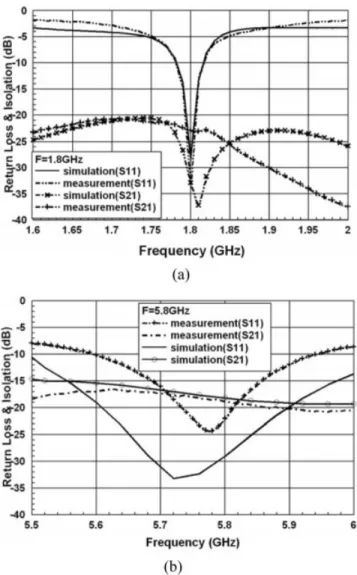
Figure 3 Simulated and measured return loss and isolation between two input ports for the proposed antenna. (a) At the lower resonant frequency (f⫽ 1.8 GHz); (b) At the higher resonant frequency (f ⫽ 5.8 GHz)
2.3. The Theoretical Principle
The diplexer operates at dual frequency band, F1 and F2. The length of the slots in Figure 1(c) and open stubs in Figure 1(a) must be designed carefully such that the maximum aperture coupling will pass through the slots to the radiating patches [10]. At the lower resonant frequency F1, the signal will pass from input port to open stubs, aperture couples to slot 1A (from port 1) or slot 2A (from port 2) and radiate to the outer ring patch. Because the feed positions of the two input ports are orthogonal, then the passing signals of the two ports are orthogonal. Therefore, the polarization states of dual ports are orthogonal. While at the higher resonant frequency F2, the signal will pass from input port to open stubs, aperture couples to slot 1B (from port 1) or slot 2B (from port 2), and radiate to the inner square patch. In order to overcome the coupling of the two patches, the gap of the two patches needs proper selection. If G is too small, the coupling will be so strong that the dual resonance states are reducing. If G is too large, the ring patch will have a small R2O/R2ivalue and the performance of the higher resonant frequency F2is attenuated [13]. In our exper-iment, we select G⫽ 4 mm and the antenna system has a good response at dual operating frequencies. In the next paragraph, we’ll present our simulation and measurement data.
3. SIMULATION AND MEASUREMENT RESULTS
The return loss and isolation for the proposed antenna are simu-lated and measured. The microstrip patch antenna is simusimu-lated
using IE3DTM. The simulated results and the measured results are shown in Figure 3. Satisfactory agreement between simulation and measurement is observed.
Figure 3(a) is the simulation and measurement results for the linear polarization at 1.8 GHz. The obtained simulated 10-dB impedance bandwidth for measurement is 2.33 and 2%. The isolation between the port 1 and the port 2 at 1.8 GHz is⫺30 dB at simulation. From the measured results, the isolation (S21) across the 1.8 GHz band is less than ⫺22 dB. The measured result agrees similar with the simulated one. A good isolation (⬍⫺20 dB) is obtained for the aperture-coupled patch antenna excited between the two different ports. Figure 3(b) is the simulation and measurement results for the linear polarization mode at 5.8 GHz. The obtained 10-dB impedance bandwidths from the measurement are about 8.69 and 6.05% for port 1 and port 2. The measurement results match with the simulated results well. The isolation between two ports is less than⫺18 dB at 5.8 GHz.
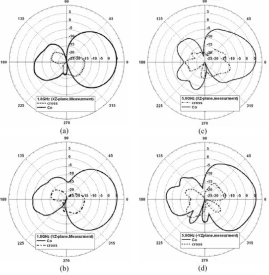
Figure 4 shows the measured radiation pattern at port 1. The peak gain measured around the main beam at 1.8 GHz is 5.81 dBi, while the peak gain is 6.38 dBi at 5.8 GHz. The measured data match well with the simulated data using IE3DTM. The crosspolarization is less than copolarization more than 20 and 18 dBi for 1.8 and 5.8 GHz. Therefore, the radiation patterns show that the proposed antenna has good linear polarization at each band.
Figure 4 Measured linear polarization radiation patterns of the proposed antenna. (a) Measured XZ-plane at 1.8 GHz; (b) Measured YZ-Plane at 1.8 GHz; (c) Measured XZ-plane at 5.8 GHz; (d) Measured YZ-Plane at 5.8 GHz
4. CONCLUSIONS
By using dual-bandpass diplexers and aperture coupling technol-ogy, our proposed dual-polarized dual-bands antenna can provide a pair of orthogonal polarization states at dual operating frequen-cies. Numerical and experimental results validate our design. ACKNOWLEDGMENT
This work was supported by the National Science Council, Tai-wan, Republic of China, under NSC 94 –2219-E-009 – 015, 95– 2221-E-009 – 044-MY3, and 95–2752-E-002– 009-PAE.
REFERENCES
1. M.K. Fries, M. Grani, and R. Vahldieck, A reconfigurable slot antenna with switchable polarization, IEEE Microwave Wireless Compon Lett 13 (2003), 490 – 492.
2. F. Yang and Y. Rahmat-Samii, A reconfigurable patch antenna using switchable slots for circular polarization diversity, IEEE Microwave Wireless Compon Lett 12 (2002), 96 –98.
3. F. Rostan and W. Wiesbeck, Design considerations for dual polarized aperture-coupled microstrip patch antennas, IEEE Antennas Propag Soc Int Symp AP-S Dig l4 (1995), 2086 –2089.
4. G.S. Parker, Y.M.M, Antar, A. Ittipboon, and A. Petosa, Dual po-larised microstrip ring antenna with good isolation, Electron Lett 34 (1998), 1043, 1044.
5. S. Maci and G.B. Gentili, Dual-frequency patch antennas, IEEE Trans Antennas Propag 39 (1997), 13–19.
6. S.Y. Lin and K.C. Huang, A compact microstrip antenna for GPS and DCS application, IEEE Trans Antennas Propag 53 (2005), 1227–1229. 7. T.W. Chiou and K.L. Wing, A compatct dual-band dual-polarized patch antenna for 900/1800 MHz cellular systems, IEEE Trans An-tennas Propag 51 (2003), 1936 –1940.
8. D.M. de Haaij, J. Joubert, and J.W. Odendaal, Diplexing feed network for wideband dual-frequency stacked microstrip patch antenna, Micro-wave Opt Technol Lett 36 (2003), 100, 101.
9. M.H. Capstick, Microstrip lowpass-bandpass diplexer toplogy, Elec-tron Lett 35 (1999), 1958 –1960.
10. P.L.Sullivan and D.H.Schaubert, Analysis of an aperture coupled microstrip antenna, IEEE Trans Antennas Propag 34 (1986), 977–984. 11. S.Y. Lin and K.L. Wong, Enhanced performances of a compact conical-pattern annular-ring patch antenna using a slotted ground plane, IEEE Trans Antennas Propag 3 (2001), 1036 –1039. 12. J.C. Liu, C.C. Chaw, K.H. Fann, and S.T. Lu, Dual-frequency
double-ring microstrip antenna with voltage/current couplings, Microwave Opt Technol Lett 21 (1998), 209 –211.
13. P.M. Bafrooei and L. Shafai, Characteristics of single- and double-layer microstrip square-ring antennas, IEEE Trans Antennas Propag 47 (1999), 1633–1639.
© 2006 Wiley Periodicals, Inc.
INTEGRATED INTERNAL PATCH
ANTENNA FOR UMTS MOBILE PHONE
APPLICATION
Saou-Wen Su,1Austin Chen,1Kin-Lu Wong,2and
Yuan-Chih Lin2
1Technology Research Development Center, Lite-On Technology
Corporation, Taipei 11492, Taiwan
2Department of Electrical Engineering, National Sun Yat-Sen
University, Kaohsiung 80424, Taiwan
Received 3 July 2006
ABSTRACT: A novel design of the internal patch antenna mounted
above and integrated with the shielding metal case for mobile phone application is presented. The antenna mainly comprises a simple
rectan-gular patch as the antenna’s top radiating patch and a shielding metal case as part of the antenna’s ground plane. The antenna is integrated to the shielding metal case through short-circuiting and occupies almost no board space on the system circuit board. In addition, possible electronic components or conducting elements in the mobile phone can be assem-bled in close proximity to the integration design at no expense of the antenna performance. Detailed results of the design example for univer-sal mobile telecommunication system (1920 –2170 MHz) operation in a mobile phone are presented and discussed. © 2006 Wiley Periodicals,
Inc. Microwave Opt Technol Lett 49: 349 –351, 2007; Published online in Wiley InterScience (www.interscience.wiley.com). DOI 10.1002/mop. 22128
Key words: antennas; mobile phone antennas; internal mobile
anten-nas; shorted patch antenanten-nas; integrated antenanten-nas; UMTS antennas
1. INTRODUCTION
Conventional internal patch antennas for mobile phone application usually use the system ground plane as the antenna’s main ground plane [1]. The side surfaces of this kind of antenna are mainly open to exterior, thus allowing the antenna’s fringing electromagnetic fields to be penetrated into the interior of the system circuit board. This phenomenon leads to an isolation distance required between the internal antenna and nearby conducting elements to lessen the antenna performance degradation or further fine tuning in the antenna structure because of some coupling effect. Very recently, the concept of integrating the internal antenna and the RF shielding metal case/wall has been considered to be a promising antenna solution [2–5]. For these designs, the shielding metal case/wall not only performs as part of the antenna’s ground plane but also provides a coupling-free region for assembling the RF modules and other components. As a result, the isolation distance is no more needed, and more compact arrangement of the internal an-tenna and associated components can be also achieved. It is also noted that, among these integration designs, the internal antenna is usually integrated to the side surface of the shielding metal case/ wall and occupies a certain board space on the system circuit board of the mobile phone.
In this article, we present a new integration design of the internal patch antenna and the shielding metal case for mobile phone application. The antenna is suitable to be stacked over and short-circuited to the shielding metal case without increasing the antenna’s height above the system ground plane as compared with that of the conventional patch antenna [1]. With the proposed design, the internal patch antenna occupies almost no board space on the system circuit board. In addition, the coupling between the antenna and associated nearby components inside the mobile phone can be also mitigated, thereby leaving the antenna perfor-mance not affected. A design example applied to a mobile phone for UMTS (universal mobile telecommunication system, 1920 – 2170 MHz) operation is demonstrated, and experimental results of the constructed prototype are presented and discussed. A study for analyzing the air-layer thickness of the antenna (i.e., the distance between the antenna’s radiating patch and the shielding metal case) on the achievable impedance bandwidth is also conducted. Moreover, effects of the presence of a nearby conducting element on the antenna performance are studied.
2. ANTENNA DESIGN
Figure 1(a) shows the configuration of the proposed internal patch antenna mounted above the RF shielding metal case for a UMTS mobile phone. The antenna is a flat rectangular metal plate and shows a low profile of h⫽ 3 mm to the shielding metal case. In this case, the patch antenna and the shielding metal case together