Modal analysis of rib antiresonant reflecting optical waveguides by
mode matching method
Chia-En Yang
*, Shih-Hsin Hsu, Yang-Tung Huang†, and Cheng-May Kwei
Department of Electronics Engineering and Institute of Electronics
National Chiao Tung University
1001 Ta-Hsueh Road, Hsinchu, Taiwan 30050, R.O.C.
ABSTRACT
In this presentation, a simple patchwork to the classical mode matching method (MMM) is proposed to analyze rib ARROWs. MMM gives the modal effective index and the lateral part of modal power loss, and the total modal loss is obtained by including the vertical part which is estimated by a simple yet physical method described here. The simplified MMM (SMMM) is also presented to analyze the effect of TE-TM couplings. Simulation results of selected rib ARROW structures are discussed and compared with those obtained by the Effective Index Method (EIM).
Keywords: rib, antiresonant reflecting optical waveguide (ARROW), leaky, mode matching method
1. INTRODUCTION
Antiresonant reflecting optical waveguides (ARROW) presents many attractive features when compared with conventional waveguides, such as large core size that facilitates coupling with fibers, single mode operation with relatively thin cladding layers, and use as a polarizer1. ARROW structure utilizes Fabry-Perot cavities as the reflectors instead of the total internal reflection, thus can guide light in a core region having lower refractive index than adjacent layer. However, it is a leaky structure. Power loss is minimized by proper design and cannot be eliminated2.
ARROW was introduced and modeled in (2-D) planar form, but lateral confinement of light is practically needed and the easy-to-fabricate (3-D) rib structure is often favored. FEM (Finite Element Method)3 or FDM (Finite Difference Method) are commonly used to study device characteristics, since analytic solutions are generally not available for 3-D waveguides. These purely numerical methods may give numerical results as desired, but no further physical insights can be inferred.
The classical and elegant mode matching method (MMM)4 provides not only a way of obtaining numerical results, but also a way of viewing the waveguiding mechanism. The method itself is a consequence of physically and mathematically rigorous derivation, and the numerical result is readily explained5. The effective index of each mode that a rib guide can support is of great importance in various design situations such as AWG (Arrayed Waveguide Grating), MMI (Multi-Mode Interference device), Mach-Zhender Interferometer, etc., in which cases the accuracy is required. Also, the modal loss of a rib ARROW device should be carefully examined. MMM is theoretically accurate in calculating the effective indices, but the modal loss described by MMM is purely lateral (x-direction) since MMM was originally developed for conventional 3-D waveguides. The leaky nature of ARROW in the vertical direction (y-direction) must be additionally taken into account. The rib ARROW modal loss is then dissected into lateral and vertical parts in this presentation. The lateral loss, along with the modal effective index, is first calculated by the classical MMM, then the modal loss is obtained by including the vertical part using the method. The effect of TE-TM coupling in device characteristics is also investigated in this presentation by comparing the calculated results of MMM and Simplified MMM (SMMM)6 which ignores TE-TM coupling in the calculation. Numerical results obtained by MMM are also compared with those by the popular and easy-to-use effective index method (EIM)7.
* E-mail: [email protected]
2. ANALYSIS BY MODE MATCHING METHOD
2.1 Mode matching method
A rib waveguide as shown in Fig.-1(a) is divided into one inner region and two outer regions. Each region is considered as a planar waveguide. Waveguiding is described by planar wave modes traveling in zigzag paths in the inner region. The interface between the inner and outer regions is the step discontinuity. Each time a wave mode bounces on the step discontinuity, reflected and transmitted waves of both TE and TM types are generated (mode couplings), regardless of the polarization of the incident wave, as shown in Fig.-1(b). In the outer region, only outward-going (transmitted) waves exist. Due to oblique incidence, a planar TE or TM wave becomes a mode with five components, instead of three. At the step discontinuity, tangential field components must be continuous, a set of equations is then constructed with unknowns related to the amplitude of each mode. By requiring non-trivial solutions, the effective indices of rib modes are acquired.
It’s been found that TE-TM coupling is generally weak, and a rib mode is dominated by a certain TE (or TM) planar mode of the inner region. This explains the usual
E
pqx orE
pqy modes. The propagation constant,k
z, of a rib mode is shared by all constituent modes. In the outer region, modes with propagation constantk
u (= ⋅
k n
0 u, wherek
0 is the free space wave number,n
u is the effective index) smaller thank
z decay away from the step discontinuity (note thatk
x=
k
u2−
k
z2 ); those with higherk
u (usually of opposite polarization to the dominant mode) propagate away at certain angles to the step discontinuity. Thusk
z is generally complex (k
z= −
β
j
α
l2
) with an imaginary part representing the lateral (x-direction) power leakage, i.e., the power transmitted from the inner region to the outer regions.2.2 Simplified mode matching method
Since the TE-TM coupling in conventional 3D waveguiding structures is usually found to be weak, it may be desirable to include only TE or TM constituent modes in calculation to reduce computation time. Further more, only the dominant TE or TM planar mode of the inner region needs to be kept in calculation. The computation time is greatly reduced (no matrix operation required) and an accurate enough result may be maintained.
Fig.-1(a) The rib ARROW. The artificial boundaries are to discretize the continuous spectrum of radiation modes.
Fig.-1(b) Scattering of a planar waveguide mode by a dielectric step discontinuity.
m θ TEm z TEn TMn TEk TMk step discontinuity
2.3 In the case of a rib ARROW
To apply MMM, constituent planar modes must first be determined. The continuous spectrum of radiation modes is discretized by placing perfectly conducting plates above and below the rib ARROW, as depicted in Fig.-1(a). The so-called ARROW mode is described by a leaky mode which is a typical radiation mode having an attenuation constant associated with it. This attenuation constant, usually obtained by transverse resonance condition9, accounts for the power loss radiating (vertically) into the substrate layer. The artificial boundaries do not affect ARROW modes extensively, since ARROW modes by design have most of its power in the core layer.
Here, it is assumed that every radiation mode, besides ARROW modes, has an attenuation constant associated with it9. Radiation modes other than ARROW modes are assumed to have far larger attenuation constants due to little proportion of power in the core layer, and do not contribute significantly to a rib mode which must be dominated by a certain planar ARROW mode of the inner region. Little amount of power that are carried by these modes dissipates rapidly and soon becomes unnoticeable as a rib mode propagates. Therefore, modal loss of a rib-ARROW mode comes from a lateral part as described by MMM and a vertical part due to losses of constituent planar modes. Let
( )
(
)
( )
exp
,
exp
,
sin
l l v n n n nP z
z
z
P z
c
α
α
θ
=
−
=
−
∑
where subscript l denotes “lateral” and v “vertical, the summation is over all constituent planar modes of the inner region,
α
n is the attenuation constant,sin
θ
n compensates for the zigzag propagation,θ
n is the incident angle on the step discontinuity, andc
n is the proportion of power carried by the n-th mode. The power carried by a rib mode as a function ofz
(the propagation direction) is then given as( )
( ) ( )
exp
,
sin
v l m l mP z
P z P z
z
α
α
θ
∝
−
+
where the m-th planar mode (one of ARROW modes) is assumed to be predominant. The total attenuation constant is
sin
m l mα
α
α
θ
=
+
.Therefore, the power loss described here is a minimum since losses from higher modes which are small are neglected. In the outer region, when
α
l is non-vanishing, constituent modes that can propagate away from the step discontinuity have exponentially decaying amplitude due to their vertical power loss, and may not extend laterally (in the x-direction) if associated with large attenuation constants (α
n), such as those with effective indices larger thann
c (cladding and substrate modes).3. NUMERICAL EXAMPLES
The device parameter values of the analytic examples for the structure in Fig. 1(a) are:λ= 1.3μm, dc = 4μm, d1 = 0.1019μm, d2 = 2μm, da = 5μm, ds = 5μm, na = 1, nc = n2 = 1.45, and n1 = ns = 3.5, where W and h to be varied. About 50 TE and 50 TM planar modes are included in the calculation. Results obtained by EIM are also shown in the following examples to be compared with those by MMM.
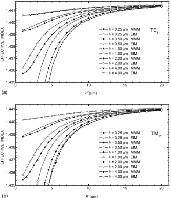
Figs.-2(a) and 2(b) show the calculated effective indices of TE11 (
E
11x , TE-predominant, fundamental rib ARROW mode) and TM11 (E
11y, TM-predominant), respectively, for various rib heights. It is clear that EIM overestimates the effective index in all cases. The discrepancy is small for low rib height (h= 0.25μm) and becomes quite noticeable as rib height increases (h = 0.5 ~ 2μm). When larger than certain rib height, this discrepancy begins to decrease (such as in the case of h = 2.5μm but not shown here for clarity) and is eventually vanishing as shown in the extreme case of h = 4μm, where the effective index of the outer region used in EIM is set to 1 (air). This is understood by noting that EIM ignores TE-TM coupling which is greater for larger structural difference between inner and outer regions. For a large enough rib height, the decrease of mode coupling is a result of small overlap integral4 between field profiles of TE (or TM) modes of the inner and outer regions. For large rib widths (W), effective indices obtained by MMM and EIM agree well in all cases due to small number of times wave modes bouncing on the step discontinuity, effectivelyreducing mode coupling.
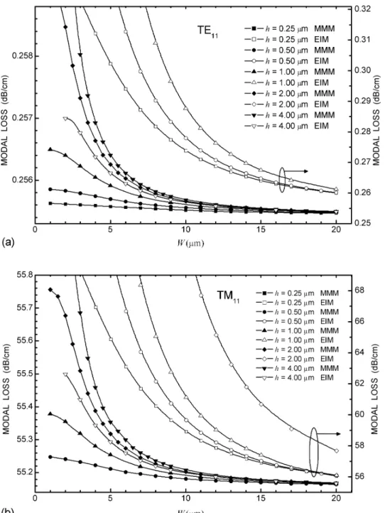
Figs.-3(a) and 3(b) show the calculated modal losses in dB/cm of TE11 and TM11 modes for various rib heights. In order to discriminate results obtained by different methods, those by MMM are shown with y-axis on the left; EIM on the right (except for h = 4μm). For TM11 mode,
α
l is at most on the order of 10-7, whereasn
α
of TM0 is on the order of 10-4. For TE11 mode,l
α
is found to be vanishing because in the outer region, either modes significantlyexcited do not laterally propagate or modes laterally propagating are not significantly excited. This is easily seen by considering effective indices of TE11 and each constituent mode, and their corresponding field profiles5. Therefore, the modal power loss of TE11 (TM11) is primarily vertical due to the dominant TE0 (TM0) of the inner region. It is seen in Fig.-3 that modal losses increase with increasing rib height, and those estimated by EIM are higher except for h = 4μm in which case they are lower. Since effective indices for h = 4μm calculated by both methods are virtually identical as indicated in Fig.-2 and modal loss calculated by using P(z) is theoretically a minimum, EIM may not be trustworthy in the case of h = 4μm. This can also be seen by comparing the results of EIM and FEM10 in this case (strip guide). As rib width gets larger, modal losses in all cases decrease due to the same reason as explained for effective indices.
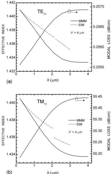
Figs.-4(a) and 4(b) show the effective index and modal loss as functions of the rib height (h) at W = 4μm for TE11 and TM11, respectively. Effective indices estimated by EIM for h > 3μm are not shown here because the effective index of the outer region can barely be determined. The light wave is hardly confined in a thin (< 1μm) core layer, since the underlying high reflectivity multilayer is designed for a core thickness of 4μm. EIM is inapplicable for h > 3 μm. The discontinuity at h ~ 2.1μm for both TE11 and TM11 cases is due to the effective index of the outer region9.
Fig. 4 Calculated effective index and modal loss as a function of rib height at a rib width of 4μm. (a) TE11 mode, (b) TM11 mode.
Before the discontinuity the effective index is that of the lowest ARROW mode, but after the discontinuity it is the second lowest ARROW mode since the lowest mode now becomes a cladding mode. It is clear that EIM overestimates the effective index for all h, and MMM estimate first decreases almost linearly with increasing h but becomes gradual for h > 2μm, consistent with what was stated about Fig.-2. Modal losses estimated by EIM are all larger than MMM and are neglected in Fig.-4 in order to clearly show the transition of MMM estimate.
Figs.-5(a) and 5(b) show the modal effective indices calculated by MMM and SMMM as functions of rib width. The difference between MMM and SMMM is a measure of the strength of TE-TM coupling. It is clearly seen that TE-TM coupling first increases as the rib height increases but begins to decrease somewhere between h = 1μm and h = 2μm. At h = 4μm, TE-TM coupling is vanishing. For W > 2.5μm, TE-TM coupling decreases with increasing rib width. These observations are similar to those of Fig.-2 and can be explained in the same way. Thus for W < 2.5μm SMMM may not be dependable since it neglects TE-TM coupling which can be strong in these narrow widths due to a larger
number of times waves bouncing on the step discontinuity. It should be noted that, by comparing Fig.-2 and Fig.-5, the difference between EIM and MMM does not stop increasing until h > 2μm, whereas that between SMMM and MMM starts to decrease at h > 1μm. Based on the fact that both EIM and SMMM ignore the TE-TM coupling, SMMM is expected to be more accurate in estimating the effective indices than EIM, since it takes into account the effect of the coupled (excited) modes (besides the fundamental mode) of the outer region.
For there to be a lateral modal loss, wave modes of the outer region must have effective indices larger than the modal effective index and are significantly excited. In a rib ARROW structure, there are always modes of the outer regions having large enough effective indices, but they are generally not significantly excited as can be seen from their field distribution profiles. Thus the oppositely polarized lowest order ARROW mode of the outer region is the only source for the lateral modal loss. SMMM precludes this possibility. Hence it gives no lateral loss and no data is shown in this presentation. However, our selected numerical examples show that the lateral loss is negligible. Thus, SMMM can be considerd as a fast substitute for MMM, unless a high accuracy is required or the rib height is low (h < 2.5μm in our example).
4. SUMMARY
We have proposed a patchwork to the classical mode matching method and used it to analyze an example of rib ARROW. The differences among rib-ARROW modal effective indices obtained by MMM, SMMM, and EIM are around 0.5%. Hence, MMM provides a more rigorous basis to EIM, which is still the recommended method. If an accurate estimate is needed, MMM can be applied in the case of a low rib height, or the much faster SMMM in the case of a larger rib height where TE-TM coupling is negligible.
Modal loss of a rib-ARROW mode as analyzed by MMM (or SMMM) is composed of lateral and vertical parts and is dominated by the vertical part in the selected numerical examples. MMM provides a theoretical minimum of the modal loss and can be considered an assessment of EIM. It is not surprising to find that EIM may be incorrect about the modal loss in the case of a strip guide (rib height = core height) as FEM gives the same observation. However, the modal loss estimated by EIM is larger than that by our method in most cases, which means that EIM at most overestimates the modal loss and is conservative in a rib ARROW device design.
Therefore, EIM, which is much simpler to use, is still recommended as the first step in practical design interests.
REFERENCES
1 M. A. Duguay, Y. Kokubun, T. L. Koch, and L. Pfeiffer, “Antiresonant reflecting optical wageguides in SiO2-Si multilayer
structures,” Appl. Phys. Lett., 49, No. 1, pp. 13-15, 1986.
2 T. Baba and Y. Kokubun, “Dispersion and radiation loss characteristics of antiresonant reflecting optical waveguides – numerical results and analytical expressions,” IEEE J. Quantum Electron., 28, No. 7, pp. 1689-1700, 1992.
3 J. C. Grant, John C. Beal, and N. J. P. Frenette, “Finite element analysis of the ARROW leaky optical waveguide,” IEEE J.
Quantum Electron., 30, No.-5, pp. 1250-1253, 1994.
4 S. T. Peng and A. A. Oliner, “Guidance and leakage properties of a class of open dielectric waveguides: part I–mathematical formulations,” IEEE Trans. Microwave Theory Tech., MTT-29, No. 9, pp. 843-854, Sept. 1981.
5 A. A. Oliner, S. T. Peng, T. I. Hsu, and A. Sanchez, “Guidance and leakage properties of a class of open dielectric waveguides: part II–new physical effects,” IEEE Trans. Microwave Theory Tech., MTT-29, No. 9, pp.855—869, Sept. 1981.
6 M. Koshiba and M. Suzuki, “Simple equivalent network for rectangular dielectric image guides,” Electron. Lett., 18, No.-11, pp.-473-474, 1982.
7 B. V. Borges, and A. C. Cesar, “Leakage loss analysis in rib type waveguides by the effective index method,” SBMO/IEEE
MTT-S IMOC99 proceedings, pp. 129-133, 1999.
8 I. Garces, J. Subias, and R. Alonso, “Analysis of the modal solutions of rib antiresonant reflecting optical waveguides,” J.
9 W. Huang, R. M. Shubair, A. Nathan, and Y. L. Chow, “The modal characteristics of ARROW structures,” J. Lightwave Tech.,
10, No. 8, pp. 1015-1022, 1992.
10 H.E. Hernandez-Figueroa, F.A. Fernandez, Y. Lu, and J.B. Davies, “Vectorial finite element modeling of 2D leaky waveguides,”