立即的資料壓縮與解壓縮加速器在高度可擴充性DVB-MHP的JVM軟硬體協同設計
50
0
0
全文
(2) 立即的資料壓縮與解壓縮加速器 在高度可擴充性 DVB-MHP 的 JVM 軟硬體協同設計 On-the-fly Compression and Decompression Accelerator for JVM HW/SW co-design of a high upgradeable DVB-MHP Terminal. 研 究 生:黃士嘉. Student:Shih Chia, Huang. 指導教授:蔡淳仁. Advisor:Chun Jen, Tsai. 國 立 交 通 大 學 資 訊 工 程 系 碩 士 論 文 A Thesis Submitted to Department of Computer Science and Information Engineering College of Electrical Engineering and Computer Science National Chiao Tung University in partial Fulfillment of the Requirements for the Degree of Master in Computer Science and Information Engineering June 2005 Hsinchu, Taiwan, Republic of China. 中華民國九十四年六月. II.
(3) 國. 立. 交. 通. 大. 學. 博碩士論文全文電子檔著作權授權書 (提供授權人裝訂於紙本論文書名頁之次頁用). 本授權書所授權之學位論文,為本人於國立交通大學 ____組,. 93. 資訊工程. 系所 __. 學年度第_2_學期取得碩士學位之論文。. 論文題目:立即的資料壓縮與解壓縮加速器在高度可擴充性 DVB-MHP 的 JVM 軟硬 體協同設計 指導教授:蔡淳仁 博士. ■ 同意. □不同意. 本人茲將本著作,以非專屬、無償授權國立交通大學與台灣聯合大學系統圖書館: 基於推動讀者間「資源共享、互惠合作」之理念,與回饋社會與學術研究之目的, 國立交通大學及台灣聯合大學系統圖書館得不限地域、時間與次數,以紙本、光 碟或數位化等各種方法收錄、重製與利用;於著作權法合理使用範圍內,讀者得 進行線上檢索、閱覽、下載或列印。 論文全文上載網路公開之範圍及時間: 本校及台灣聯合大學系統區域網路. ■ 中華民國 94 年 8 月 15 日公開. 校外網際網路. ■ 中華民國 94 年 8 月 15 日公開. 授 權 人:黃士嘉 親筆簽名:______________________ 中華民國. 94 年. 8. 月. 3 日. III.
(4) 國. 立. 交. 通. 大. 學. 博碩士紙本論文著作權授權書 (提供授權人裝訂於全文電子檔授權書之次頁用). 本授權書所授權之學位論文,為本人於國立交通大學. 資訊工程. 系所. 學年度第__2__學期取得碩士學位之論文。. ______組, 93. 論文題目:立即的資料壓縮與解壓縮加速器在高度可擴充性 DVB-MHP 的 JVM 軟硬體協同設計 指導教授:蔡淳仁 博士 ■ 同意 本人茲將本著作,以非專屬、無償授權國立交通大學,基於推動讀者間「資 源共享、互惠合作」之理念,與回饋社會與學術研究之目的,國立交通大學 圖書館得以紙本收錄、重製與利用;於著作權法合理使用範圍內,讀者得進 行閱覽或列印。 本論文為本人向經濟部智慧局申請專利(未申請者本條款請不予理會)的附 件之一,申請文號為:____________________,請將論文延至____年____ 月____日再公開。. 授 權 人:黃士嘉 親筆簽名:______________________ 中華民國. 94 年. 8. 月. 3 日. IV.
(5) 國家圖書館博碩士論文電子檔案上網授權書 ID:GT009117582 本授權書所授權之論文為授權人在國立交通大學 電機資訊 學院 資訊工程 系 所 _________ 組 _93_學年度第_2_學期取得碩士學位之論文。 論文題目:立即的資料壓縮與解壓縮加速器在高度可擴充性 DVB-MHP 的 JVM 軟硬 體協同設計 指導教授:蔡淳仁 博士 茲同意將授權人擁有著作權之上列論文全文(含摘要),非專屬、無償授權國家 圖書館,不限地域、時間與次數,以微縮、光碟或其他各種數位化方式將上列 論文重製,並得將數位化之上列論文及論文電子檔以上載網路方式,提供讀者 基於個人非營利性質之線上檢索、閱覽、下載或列印。. ※ 讀者基於非營利性質之線上檢索、閱覽、下載或列印上列論文,應依著作權法相關規定辦理。. 授權人:黃士嘉 親筆簽名:_______________ 民國. 94. 年. 8 月. 3. 日. V.
(6) 國立交通大學 論文口試委員會審定書 本校. 資訊工程系 碩士班. 黃士嘉. 君. 所提論文: On-the-fly Compression and Decompression Accelerator for JVM HW/SW co-design of a high upgradeable DVB-MHP Terminal 立即的資料壓縮與解壓縮加速器在高度可擴充性 DVB-MHP 的 JVM 軟硬體協同設計. 合於碩士資格水準、業經本委員會評審認可。 口試委員:. 指導教授:. 系主任: 中 華 民 國 九十四 年 六 月 二十二 日 VI.
(7) 立即的資料壓縮與解壓縮加速器在高度可擴充性 DVB-MHP 的 JVM 軟硬體協同設計. 學生:黃士嘉. 指導教授:蔡淳仁 博士. 國立交通大學資訊工程學系﹙研究所﹚碩士班. 摘. 要. 在嵌入式即時系統中,記憶體的使用與電能的消耗一直是很重要的議 題,我們在數位電視標準中的 DVB/MHP 的 Java processor 中,加入物件資 料壓縮與解壓縮的機制,以達到較少的記憶體的使用、較低電量的消耗, 進而提升整體的執行效率。 目前在 JVM 中,都採用軟體的方式來做資料壓縮與解壓縮的機制,這 樣通常會造成整體的執行效率降低。我將設計硬體的壓縮與解壓縮加速 器,利用硬體的平行度來提升整體的執行效能。 達到的目的,分別條列如下: (1) 減少記憶體的使用 (2) 達到低電量的消耗 (3) 減少整體執行時間 我們選用的實驗平台是 Xilinx ML-310 的嵌入式發展平台,可程式化的 邏輯陣列,主要包含:兩個 IBM Power PCTM 405(PPC 405)處理器、30816 Logic Cell、2,448 kb BRAM(block RAM)。. i.
(8) On-the-fly Compression and Decompression Accelerator for JVM HW/SW co-design of a high upgradeable DVB-MHP terminal. Student: Shih Chia, Huang. Advisor: Dr. Chun Jen, Tsai. Institute of Computer Science and Information Engineering National Chiao-Tung University. Abstract Multimedia Home Platform (MHP) is a digital video broadcasting (DVB) standard intended to combine digital television (DTV) with the Internet and the World Wide Web. An MHP setop box is a complicated embedded system that contains both multimedia and communication components. Memory size (includes both volatile and non-volatile memory devices) and power consumption is always the main concern when designing this kind of embedded devices. One of the critical components in a DVB-MHP setop box is the Java VM. To achieve the best performance/power consumption ratio, a dedicated Java processor is often used. The goal of this thesis is to design a runtime bytecode/data compression and decompression hardware logic to a Java processor for DVB-MHP applications. Fo software-based Java VM, runtime bytecode/data compression and decompression are used to reduce the memory usage. However, the performance of the system usually decreases due to the extra overhead. To maintain performance while reducing memory usage, a hardware accelerator for real-time compression/decompression with parallel datapaths is a reasonable aproach. The proposed hardware design is implemented and verified on an FPGA platform, Xilinx ML310. Based on the experimental results, the proposed architecture is very efficient and promising for practical applications.. ii.
(9) 誌. 謝. 在這篇論文裡,覺得學習的非常扎實,有 Java Processor、Power PC、IBM Bus Core-connect,和在 Xilinx ML-310、Xilinx Spartan III 方面的實作,也讓我深 深的體會到系統方面的實作,真的不太容易,需要花費很多的時間和心思。. 非常感謝我的指導教授 蔡淳仁老師給我的教導和鼓勵,Xilinx 的資深工程師 何奇旺老師在板子上的許多的指導與協助,也很感謝實驗室的所有成員給我的鼓 勵,還有我的家人、朋友給我的鼓勵和支持。. iii.
(10) Table of Content 摘要 ....................................................................................................................................i Abstract..............................................................................................................................ii 誌謝 ..................................................................................................................................iii Table of Content ................................................................................................................iv List of Figures .................................................................................................................... v List of Tables.....................................................................................................................vi 1. Introduction ................................................................................................................ 1 1.1. On-the-fly Compression and Decompression Accelerator ............................ 1 1.2. OCD for Java VMs Using HW/SW Co-design Approach............................. 2 1.3. Overview of this Thesis ............................................................................... 2 2. Previous Work ............................................................................................................ 3 2.1. Java System................................................................................................. 3 2.2. Java Virtual Machine ................................................................................... 5 2.3. Java Processor ............................................................................................. 6 2.4. Main Reference Papers................................................................................ 7 2.4.1. Heap Compression for Low Memory Java Systems ............................. 7 2.4.2. Fast Interpreters for Huffman Compressed Bytecode ........................... 8 2.4.3. Hardware Data Compression for Energy Minimization ........................ 9 3. Problem Formulation ................................................................................................ 10 3.1. JOP Runtime System ................................................................................. 10 3.2. Overview of JOP ....................................................................................... 11 3.3. Datapath of JOP ........................................................................................ 12 3.4. Xilinx ML-310 .......................................................................................... 16 3.5. Discussion................................................................................................. 19 3.6. Approach................................................................................................... 20 4. The Architecture of JOP on ML-310 ......................................................................... 22 4.1. System Overview ...................................................................................... 22 4.2. IPIF Architecture....................................................................................... 23 4.2.1. IPIF Features ..................................................................................... 23 4.3. Our Modify Architecture ........................................................................... 24 5. Proposed VLSI Compressor/Decompressor Architecture........................................... 25 5.1. JOP File Format ........................................................................................ 25 5.2. Description of the Compression Schemes .................................................. 27 5.2.1. Variable-Length Coding Scheme........................................................ 27 5.2.2. Zero-Removal Compression .............................................................. 28 5.2.3. Difference Compression .................................................................... 29 5.3. Hardware Implement ................................................................................. 29 5.3.1. Hierarchical Design ........................................................................... 29 5.3.2. On-the-fly Compression and Decompression Accelerator .................. 30 6. Experimental Results ................................................................................................ 32 6.1. Java Benchmark Programs......................................................................... 32 6.1.1. Sieve of Eratosthenes......................................................................... 32 6.1.2. Kfl ..................................................................................................... 32 6.1.3. UDP/IP.............................................................................................. 33 6.2. Main Memory Compression Ratio............................................................. 33 6.3. Fetch time Reduction of Java Binaries....................................................... 34 7. Conclusion & Future Work ....................................................................................... 36 REFERENCES................................................................................................................. 37 iv.
(11) List of Figures Figure 1. Java System......................................................................................................... 3 Figure 2. Architecture of the JVM ...................................................................................... 4 Figure 3. Implement JVM three methods ............................................................................ 5 Figure 4. The general Java Runtime System...................................................................... 10 Figure 5. The JCC and JOP Runtime System .................................................................... 11 Figure 6. Block diagram of JOP........................................................................................ 12 Figure 7. Pipeline of JOP.................................................................................................. 12 Figure 8. Java Bytecode Fetch .......................................................................................... 13 Figure 9. JOP instruction fetch.......................................................................................... 14 Figure 10. Decode and Address Generation ...................................................................... 15 Figure 11. Execution......................................................................................................... 16 Figure 12. ML-310 Board and Front Panel Detail ............................................................. 18 Figure 13. ML-310 High-Level Block Diagram ................................................................ 19 Figure 14. ML-310 SoPC.................................................................................................. 22 Figure 15. IPIF Features ................................................................................................... 23 Figure 16. OCDA Interface between JOP and IPIF ........................................................... 24 Figure 17. Main memory contents .................................................................................... 26 Figure 18. Table-Based compression algorithm................................................................. 27 Figure 19. Table-Based compression example................................................................... 28 Figure 20. Zero-Removal compression algorithm ............................................................. 28 Figure 21. Zero-Removal compression example ............................................................... 28 Figure 22. Difference compression algorithm ................................................................... 29 Figure 23. Difference compression example ..................................................................... 29 Figure 24. Hardware Hierarchical Design ......................................................................... 30 Figure 25. OCDA Architecture ......................................................................................... 31 Figure 26. Pictures of a Kippfahrleitung Mast in Down and Up Position........................... 33 Figure 27. Each compression reduction ............................................................................ 34 Figure 28. Execution time with oscilloscope..................................................................... 35. v.
(12) List of Tables Table 1. Comparison of Java hardware................................................................................ 7 Table 2. The garbage collection strategies ........................................................................... 7 Table 3. The first part of this table gives the absolute heap sizes in KBs, and the second part gives the values (heap sizes) normalized with respect to that of the MC collector................ 8 Table 4. Energy and Memory Traffic Reductions................................................................. 9. vi.
(13) 1. Introduction In this chapter, we will give an introduction to On-the-fly Compression and Decompression Accelerator (OCDA) for Java VM. Some analysis of the performance of an OCDA will be presented. In addition, a mechanism that adopts different compression schemes to achieve better compression ratio based on the characteristics of DVB-MHP applications [1] will be proposed.. 1.1. On-the-fly Compression and Decompression Accelerator Due to its portability, Java is becoming a popular software platform for embedded devices. However, embedded devices are constrained by memory size and power consumption. Both factors are not the main concern of a Java runtime environment when Java was first proposed in 1991 and announced in 1995. Therefore, to increase the performance/resource consumption ratio, a on-the-fly data compression and decompression mechanism can minimize the use of memory and also arrive at lower energy consumption. The advantages and disadvantages of an On-the-fly Compression and Decompression (OCD) mechanism is as follows: Advantages: 1.. Reduction of memory usage. 2.. Decrease of data communication time. 3.. Slash of memory access time. 4.. Cutback of power consumption. Disadvantages: 1. Extra design effort 2. Computational overhead of data compression and decompression Due to the computational overhead of data compression and decompression, a software-based OCD module generally suffers some performance degradation. In this thesis, a hardware-assisted solution is proposed to reduce data compression and decompression overhead. The proposed hardware OCD module has all the advantages of a software-based OCD module without the drawback of performance degradation. 1.
(14) 1.2. OCD for Java VMs Using HW/SW Co-design Approach Java is a dynamically-typed pure object-oriented language developed by Sun Microsystems in the early 1990. In general, Java language has some excellent features such as being secure and platform-independent. However, easy portability of Java programs across platform comes at a cost of low execution performance. To increase performance, OCD is sometime used to perform real-time data compression and decompression between main memory and internal Java VM cache. To be more precise, before a Java binaries (e.g. jar files or class files) is ready for execution, an offline (or semi real-time) compression pass is performed on the Java binaries so that the input binaries to the Java VM is smaller. By doing this, the main memory access time will be greatly reduced. This is true even for a processor-based software VM implementation. The compressed Java binaries are then de-compressed on-the-fly inside the Java VM for execution. Since a large portion of power consumption comes from main memory accesses, this approach can reduce the power consumption as long as the on-the-fly de-compressor is efficient.. 1.3. Overview of this Thesis Chapter 2 gives the introduction to the Java system and three major implementation approaches for Java VM (JVM). Among these approaches, the Java processor approaches is adopted in this thesis for its good performance/resource ratio for real-time embedded systems. Chapter 2 also presented some details of existing Java data compression and decompression mechanisms. In chapter 3, an introduction to the Java Optimized Processor (JOP) is given. JOP is designed by Martin Schoeberl [5]. We have ported it to the Xilinx ML-310 Embedded Development Platform. Some analysis of OCD for JOP is also discussed in this chapter. The required modification to JOP in order to port it to ML-310 is presented in chapter 4. Chapter 5 describes the compression and decompression algorithms adopted in our design and the proposed OCD architecture. Some experimental results are presented in chapter 6. Finally, the conclusion and some discussions are given in Chapter 7.. 2.
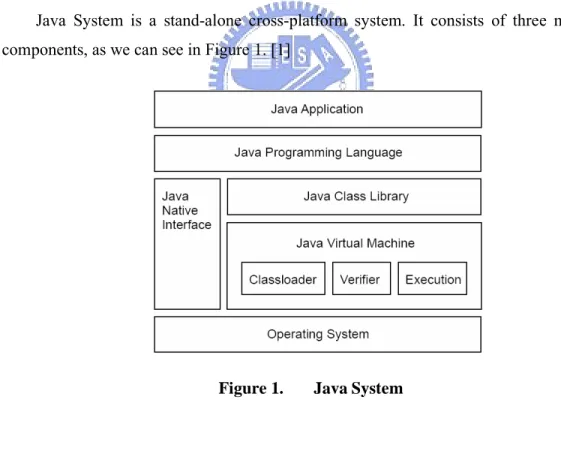
(15) 2. Previous Work In this chapter, we introduce the Java system including Java programming language, Java class library, and Java virtual machine (JVM). JVM is the core component of a Java System. Typical implementation approaches for a JVM include: interpreters, Just-in-Time (JIT) compilers, and Java processors. In this thesis, we adopt a java processor to implement OCDA-enabled JVM. The requirements for the embedded implementation of JVM are constrained by memory size and power consumption. After an introduction to Java runtime systems, we will discuss several papers about compression technologies for different Java Systems.. 2.1. Java System Java System is a stand-alone cross-platform system. It consists of three main components, as we can see in Figure 1. [1]. Figure 1.. 1.. Java System. Java Programming Language Java Programming Language[1], named Bytecode by Sun, is an intermediate. instruction set, with an accompanying execution environment. This combination helps to make write once, run anywhere possible. 3.
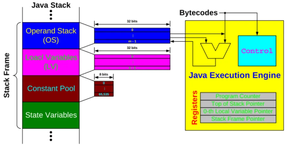
(16) Java Bytecode, comprises one-byte opcode and zero-to-five bytes operands, is variable-length instruction format, but there are some one-byte instructions which also encode operand inside.. 2.. Java Class Library Java Class Library [1] which is defined as part of the Java specification between. Java Programming Language and Java Virtual Machine. Java Application Programming Interfaces (API) is organized as sets of packages, in respect of z. java.lang – object, data types, commonly used mathematical functions, system operations like dynamic loading of classes, etc.. z. java.util – enumeration, random number generation, string tokenizer, classes for accessing Java arrays, etc.. z. 3.. java.io – stream I/O in a sequence of 8-bit bytes. Java Virtual Machine (JVM) The Java Virtual Machine (JVM) [1][1][1] provides the runtime framework. executes java bytecode programs and it is a CISC stack-based architecture. Java makes cross-platform is due to the existence of JVM. The JVM, abstract machine with cross-platform capability, run-time data areas contain Program Counter, Java Stack, Heap, Method Area, and Runtime Constant Pool.. Java Stack Bytecodes 32 bits. Operand Stack (OS). .... 0 m-1. Control. .... 0 n-1. Java Execution Engine. 8 bits 0. Registers. Constant Pool. .... Stack Frame. 32 bits. Loacl Variables (LV). 65,535. State Variables. Program Counter Top of Stack Pointer 0-th Local Variable Pointer Stack Frame Pointer. Figure 2. Architecture of the JVM 4.
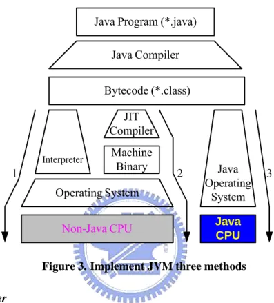
(17) 2.2. Java Virtual Machine There are three major implementations for JVM as described below and shown in Figure 3. [1] [1]. Java Program (*.java) Java Compiler Bytecode (*.class) JIT Compiler Interpreter. 1. Machine Binary. 2. Operating System Non-Java CPU. Java Operating System. 3. Java CPU. Figure 3. Implement JVM three methods 1.. Interpreter Interpreter [1][1][1] is the traditionally used way to execute Java Bytecode. The. interpreter is composed of a big time-consuming loop to map each Java bytecode into native code sequence, and the main disadvantage is the high execution overhead.. 2.. Just-in-Time Compilation Just-in-Time (JIT) Compiler [1] translates Java bytecodes to native codes during. runtime and stores the compiled codes. Then we can use the compiled codes directly next time without compiling them again. To reduce the compilation overhead, current JVM operate in mixed mode: Java methods are executed in interpreter mode and call frequency is monitored. Often-called methods, the hot spots, are often compiled to native code. Due to compilation during runtime, execution times are not predictable. JIT compilation wasn’t suited for embedded real time system.. 5.
(18) 3.. Java Processor Java Processor [1] [1] is a stack hardware machine with Java Bytecodes as native. instruction set. The solution can result in a small processor with predictable execution time and memory-efficient suited for embedded real time system.. 2.3. Java Processor There are two different approaches to implement Java processor by hardware as described below and shown in Table 1. [1] [1] [1]. 1.. Stand-alone Java Processor Java processors are stack architectures with an instruction set that resembles the. java bytecodes form the JVM.. 2.. Java/RISC Dual Processor Java bytecodes are executed on the Java and RISC core. In general, the java. coprocessor, is an accelerator, is integrated into the same chip as the RISC main processor.. Type Jazelle. JSTAR. picoJava 1999 year aJile. Co-Processor. Co-Processor Processor Processor. Target Technology ASIC 0.18µ ASIC 0.18µ Softcore. 2000 year FemtoJava 2001 year. Speed. Java. [MHz]. Standard. 12k gates. 200. 30k gates. 104. 128k gates. No realization. 25k gates. ASIC 0.28µ. ROM. 100. Processor. Xilinx FPGA. 2600 LCs. 20. Processor. Altera Flex 10K. 2000 LCs. 4. 6. J2ME CLDC Full. Memory. 2000 year Komodo. Size. J2ME CLDC Subset:50 bytecodes Subset:69 bytecodes.
(19) Moon. 3660 LCs,. Processor. Altera FPGA. Processor. Xilinx FPGA. Processor. Altera, Xilinx FPGA. 4KB RAM. 2000 year LightFoot 2001 year JOP. 3400 LCs,. 2001 year. 1830 LCs, 3KB RAM. 40. 100. J2ME CLDC. 1. Comparison of Java hardware. 2.4. Main Reference Papers 2.4.1. Heap Compression for Low Memory Java Systems This paper proposes a set of memory management strategy to reduce heap footprint of embedded Java applications that execute under memory constraints. There are several new garbage collectors proposed, and we distribute in Table 2. [1]. Breaking Scheme. Compaction. Compression. Reference. Down. Lazy. Large. Allocation. Object Mark-Swap. No. No. Direct. No. No. Mark-Compact. Yes. No. Direct. No. No. Mark-Compact-Lazy- Allocate. Yes. No. Direct. Yes. Yes. Mark-Compact-Compress. Yes. Yes. Handle. No. No. Yes. Yes. Handle. Yes. Yes. Mark-Compact-Compress-Lazy-All ocate. 2. The garbage collection strategies The Mark-Sweep (MS) and Mark-Compact (MC) are conventional collectors. The Mark-Compact-Compress (MCC) collector compresses objects when heap 7.
(20) compaction is not sufficient for creating space for the current allocation request, and the Mark-Compact-Lazy Allocate (MCL) is based on lazy allocation, which means no heap space is allocated unless the object is used after breaking large objects, of object portions. We combine MCC and MCL, and present Mark-Compact-Compress-Lazy (MCCL), which outperforms both MCC and MCL. Table3 gives the minimum heap sizes for each benchmark using different garbage collectors. The results in Table 3 is that, compared to the MC collector, the MS collector requires 47.9% more heap space on the average. In regard to MC, MCL and MCC bring down the heap memory requirements of our benchmarks by 9.5% and 10.8%, respectively; (the average reduction with respect to MS is around 40%). Combing them in MCCL results in even more heap memory space saving (21% on the average) . 3. The first part of this table gives the absolute heap sizes in KBs, and the second part gives the values (heap sizes) normalized with respect to that of Minimum Heap Size (KB). Average. Normalized against MC (%). MS. MC. MCL. MCC. MCCL. MS. MCL. MCC. MCCL. 132. 90. 75. 81. 65. 147.9. 90.5. 89.2. 79.0. the MC collector.. 2.4.2. Fast Interpreters for Huffman Compressed Bytecode We use canonical Huffman codes to generate compact codes with custom-sized operand fields and with a virtual machine that directly executed this compact code in this paper. They present techniques to automatically generate the new instruction formats and decoder. In effect, this automatically creates both an instruction set for a customized virtual machine and an implementation of that machine. The primary focus of this paper is to show that there are techniques to efficiently decode such compressed instructions. For speed, canonical Huffman codes should not be decoded bit by bit; instead, blocks of k bits should be used. The paper mainly proposes 8.
(21) multiple k bits look-ups specially and generates decoders given a space constrain. After the experiments on Scheme, Java benchmarks show an average execution slowdown of 9%. [1]. 2.4.3. Hardware Data Compression for Energy Minimization In this paper, they design hardware-assisted data compression as a tool for reducing energy consumption of core-based embedded systems. They explore two classes of compression methods, profile-driven and differential. The experimental results about memory traffic and energy consumption in the cache-to-memory path of a core-based system runs standard benchmark programs. The summary of achieved memory traffic reductions (ΔT) and overall energy savings (ΔE) is shown in Table 4. An average of 35.2% energy decrease is obtained by using the profile-driven compression method, while savings in the range from 4.2% to 10.1% are provided by the differential compression schemes. [1]. Profile-Driven Difference1. Difference2. Difference3. ΔE [%]. 35.24. 4.18. 10.09. 9.36. ΔT [%]. 36.10. 4.37. 10.41. 10.41. Average. 4. Energy and Memory Traffic Reductions. 9.
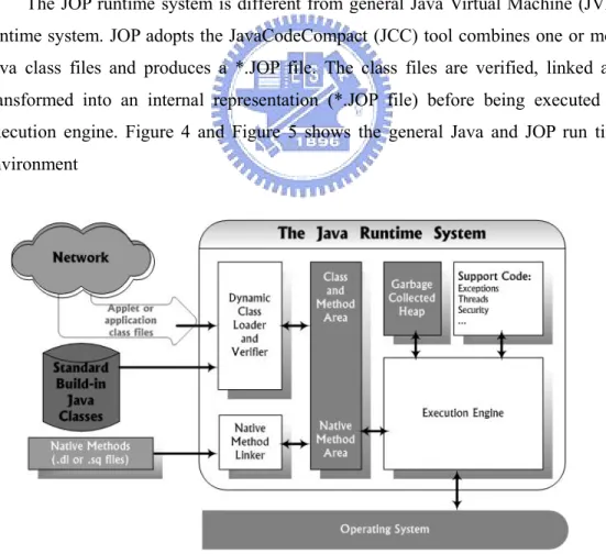
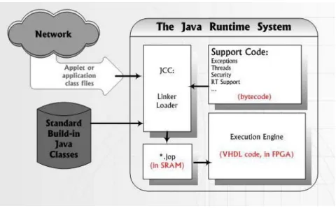
(22) 3. Problem Formulation We adopt Java Optimized Processor (JOP) design to implement the java virtual machine (JVM). It is part of Mr. Martin Schoeberl’s PhD thesis at the Technical University of Vienna, Austria. JOP is one way to use a configurable Java processor in embedded real-time systems, and Java Optimized Processor (JOP) is the main execution engine to run our DVB-MHP (Multimedia Home Platform) API. We modified JOP VHDL codes and ported it to Xilinx ML310 (Virtex-II Pro XC2VP30-FF896) Embedded Development Platform. Finally we tried to analyze experimental environment in a mathematical method.. 3.1. JOP Runtime System The JOP runtime system is different from general Java Virtual Machine (JVM) runtime system. JOP adopts the JavaCodeCompact (JCC) tool combines one or more Java class files and produces a *.JOP file. The class files are verified, linked and transformed into an internal representation (*.JOP file) before being executed on execution engine. Figure 4 and Figure 5 shows the general Java and JOP run time environment. Figure 4. The general Java Runtime System. 10.
(23) Figure 5. The JCC and JOP Runtime System. 3.2. Overview of JOP JOP’s major function units are the JOP core, a memory interface, a number of I/O devices and the module extension, as shown in Figure 6. [1] [1] [1] [1] [1] [1]. Figure 6. Block diagram of JOP 11.
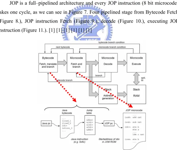
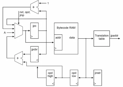
(24) The JOP core contains the four pipeline stages bytecode fetch, microcode fetch, decode, execute, and we will introduce the JOP pipeline detail in the 2.3 section. The JOP core reads bytecode instructions through dedicated buses (BC address and BC data) from the memory interface. And the JOP core transfers Data (A, B, Data) and a number of control signals from the extension module. The memory interface, contains the bytecode cache, provides a connection between the main memory and JOP core. The extension module controls read and write to and from between the JOP core, the memory, and IO modules. The I/O interface contains peripheral devices, such as the system time, a serial interface and application-specific devices.. 3.3. Datapath of JOP JOP is a full–pipelined architecture and every JOP instruction (8 bit microcode) takes one cycle, as we can see in Figure 7. Four pipelined stage from Bytecode Fetch (Figure 8.), JOP instruction Fetch (Figure 9.), decode (Figure 10.), executing JOP instruction (Figure 11.). [1] [1] [1] [1] [1] [1]. Figure 7. Pipeline of JOP Stage1: Java Bytecode Fetch 12.
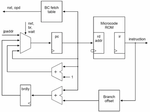
(25) The first pipeline stage can be seen in fig.8. There are some actions in this stage. 1. All bytecode are fetched from internal memory (bytecode ram). This memory, the instruction cache, is filled on function call and return. 2. Every bytecode is mapped through jtbl to an address for the microcode rom (jpaddr). It is also stored in a register for later use as operand. 3. Since jpc is also used to read operands, the program counter is stored in jpcbr during an instruction fetch. 4. Jinstr to decode the type of a branch and jpcbr to calculate the target address. Figure 8. Java Bytecode Fetch. Stage 2: JOP instruction Fetch The second pipeline stage can be seen in fig.9. JOP micro code that implements the JVM is stored in the memory labeled jvm rom. There are some actions in this stage. 1.. The program counter pc is incremented during normal execution. If the instruction is labeled with nxt a new bytecode is requested from the first stage and pc is loaded with jpaddr.. 2.. Jpaddr is the starting address for the implement of that bytecode. This 13.
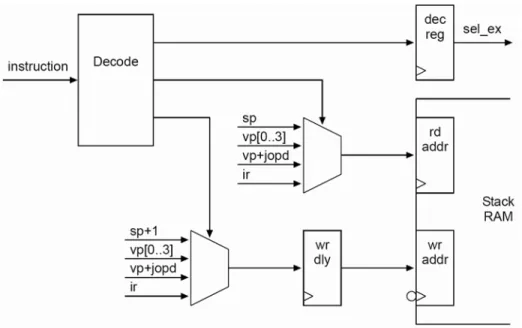
(26) label and the one for a bytecode operand load (opd) are stored in bc-fetch. 3.. brdly holds the target for a taken conditional branch, and many destinations share the same offset. A table (offset) is used to store these relative offsets. This indirection makes it possible to use only five bits in the instruction coding for branch targets and allow larger offsets.. 4.. The three tables bc-fetch, offset and jtbl, from the bytecode fetch stage, are generated during assembly of the JVM code.. Figure 9. JOP instruction fetch. Stage 3: Decode and Address Generation The third pipeline stage shown in fig.10 provides two functions. JOP instructions are decode for the execution stage and addresses for read and write accesses of the stack ram are generated.. 14.
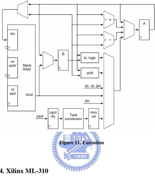
(27) Figure 10. Decode and Address Generation. Stage 4: Execute The fourth pipeline stage shown in fig.11 TOS and TOS-1 are implement as register A and B. Every arithmetic/logic operation is performed with A and B as destination. All load operations, local variables, internal register, external memory and periphery, result in the value loaded in A. Therefore no write back pipeline stage is necessary. A is also the source for store operations. Register B is never accessed directly. It is read as implicit operand or for stack spill on push instructions and written during stack spill and fill.. 15.
(28) Figure 11. Execution. 3.4. Xilinx ML-310 The ML310 Embedded Development Platform, Figure 12, is a versatile Virtex-II Pro XC2VP30-FF896 based platform for rapid prototyping and system verification. The ML-310 includes dual IBM PowerPCTM 405 (PPC405) processors, 30,816 logic cells, 2,448 kb of block RAM (BRAM), available in the FPGA. [1] Description of the ML-310 fabric follows: z. Dual IBM PowerPCTM 405 Core . z. Max frequency : 300MHz. Processor Local Bus (PLB)/On-chip Peripheral Bus (OPB)/ On-chip Memory (OCM) . z. 100 MHz. 30,816 Logic Cells. 16.
(29) z. 8 RocketIOTM. z. 2,448 kb BRAM. z. 136 Xtreme Multipliers. z. 256 MB DDR DIMM . z. Multi-Gigabit Transceiver blocks (MGTs). 100 MHz ; 64-bit. System ACE™ CF controller . 512 MB CompactFlash card. z. Onboard 10/100 Ethernet NIC. z. 4 PCI slots ( 3.3V and 5V) . 33 MHz ; 32-bit. z. LCD character display and cable. z. FPGA serial port connection. z. RS-232 mini-cable. z. Personality module interface for RocketIO and LVDS access. z. Standard JTAG connectivity. z. ALi Super I/O . 1 parallel and 2 serial ports;. . 2 USB ports;. . 2 IDE connectors;. . GPIO;. . SMBus Interface;. . AC97 Audio CODEC;. . PS/2 keyboard and mouse ports;. . ATX power supply. 17.
(30) Figure 12. ML-310 Board and Front Panel Detail. 18.
(31) 3.5. Discussion After introducing our environment and platform, the JOP IP is added on the OPB or PLB bus, and DDR-SDRAM is added on the same bus. A memory initialization file, on the DDR-SDRAM, is from the Java application file (package_App.jop) that is read by the JOP of the main memory. ¾. Before adding OCDA, we break down among external ram, bus and internal ram during execution Java Program 1. access data from External ram(DDR-SDRAM) 2. OPB or PLB Data Communication 3. access data from internal ram( JOP cache). ¾. After Adding OCDA, we break down among external ram, bus, OCDA and internal ram 1. access data from External ram(DDR-SDRAM) 2. OPB or PLB Data Communication 3. Data Compression and Decompression 4. access data from internal ram( JOP cache) We can expect reduction of execution time and power consumption for 1, 2, and. 4, but there will be an extra overhead for 3.. Figure 13. ML-310 High-Level Block Diagram 19.
(32) 3.6. Approach We will mathematically denote Main Memory usage, memory traffic, and energy.. Main Memory usage Usage_external ram ( ) : the usage of External ram Before adding OCDA: ¾. Usage_external ram (original). After adding OCDA: ¾. Usage_external ram (new ). Reduction ¾. Usage_external ram (reduce)= Usage_external ram (original) – Usage_external ram (new ). Memory traffic Time_external ram ( ) : access data from External ram time Time_communication ( ) : OPB or PLB Data Communication time Time_ODCA ( ) : Data Compression and Decompression time Time_interanl ram ( ) : access data from internal ram time. Before adding OCDA: ¾. Time_total (original)= Time_external ram ( original) + Time_communication (original) + Time_OCDA (original ) + Time_internal ram ( original ). After adding OCDA ¾. Time_total (new)= Time_external ram ( new) + Time_communication (new) + Time_OCDA (new) + Time_internal ram (new). Reduction ¾. Time_total (reduce)= Time_total (original) - Time_total (new ). 20.
(33) Energy Power_external ram ( ) : access data from External ram energy Power_communication():OPB or PLB Data Communication energy Power_ODCA ( ) : Data Compression and Decompression energy Power_interanl ram ( ) : access data from internal ram energy. Before adding OCDA: ¾. Power_total (original)= Power_external ram ( original) + Power_communication (original) + Power_OCDA (original ) + Power_internal ram ( original ). After adding OCDA ¾. Time_total (new)= Power_external ram ( new) + Power_communication (new) + Power_OCDA (new) + Power_internal ram (new). Reduction ¾. Power_total (reduce) = Power_total (original) - Power_total (new ). 21.
(34) 4. The Architecture of JOP on ML-310 The JOP has been ported to many FPGA devices. Our porting to ML-310 is based on the Xilinx Spartan-3 [18] port of JOP. The Sparatn-3 Start Kit implementation of JOP is not suitable for execution of larger Java applications due to its small main memory size and lack of many external I/O support. The Xilinx ML-310 platform is on the other hand much more suitable for DVB-MHP applications.. 4.1. System Overview To port the JOP IP to Xilinx ML-310 platform [17], we must connect the JOP Intellectual Property (IP) to the IBM CoreConnect OPB (or PLB) bus [19][20] (see Figure 14) so that it can communicate with the DDR SDRAM and the PowerPC core. Under the IBM CoreConnect bus architecture, various hardware IPs are connected to the OPB (or PLB) bus via the Intellectual Property Interface (IPIF). The OPB (or PLB) IPIF is a interface module for attaching an IP solution to the IBM-defined OPB (or PLB) Bus, the details of IPIF will be presented in the next section.. Dedicated Hard IP. Flexible Soft IP DCR Bus. PowerPC 405 Core Our Modify JOP IP Arbi ter. Hi-Speed Peripherie. Instruction. Our Modify JOP IP. Data. PLB. OPB. Processor Local Bus. e.g. Memory Controlle. Bus Bridge. Hi-Speed Peripherie. Etherne Interrupt CNTL. ZBT SSRAM Off-Chip Memory. On-Chip Peripheral Bus. DDR SDRAM SDRAM. Figure 14. ML-310 SoPC 22. II. Arbi ter. GPI Serial Ports UART.
(35) 4.2. IPIF Architecture The IPIF architecture allows various fully parameterized IPIF modules, e.g. the Read and Write FIFO, DMA/SG, Interrupt Controller, and the Reset block, to attach to the IPIC inside the IPIF and to utilize the register and/or SRAM interfaces (see Figure 15). The IPIF has two basic functions: 1.. To facilitate attachment of devices to the OPB in a standard way.. 2.. To provide services that are useful to different classes of IP.. Figure 15. IPIF Features. 4.2.1. IPIF Features The IPIF contains the capabilities and features summarized below: z. Slave interface 9. Separate Address, Data-in and Data-out Buses.. 9. Transaction Qualification: Read Req, Write Req, Byte Enable, Burst. 9. Transaction Response: Read Ack, Write Ack, Error, Retry, Timeout Suppression. z. Master interface 9. Bus Address. 9. Local Address 23.
(36) 9. Single and burst transactions. 9. Transaction Qualification: Read Req, Write Req, Byte Enable, Burst, Bus Lock. 9. Transaction Response: separate Read and Write Acks, Transaction Acks, Error, Retry, Timeout. 4.3. Our Modify Architecture Figure 16 illustrates the CoreConnect interface architecture for JOP. The OCDA module is added between the JOP IP and DDR SDRAM to transfer the OCDA compressed DATA on bus through IPIF. A detailed discuss of the design of the OCDA module will be presented in chapter 5.. Our Modify JOP IP Internal RAM. On-the-fly Compression/Decomppression Acceleraor. IPIF. Arbiter. OPB or PLB Bus. DDR SDRAM. Figure 16. OCDA Interface between JOP and IPIF. 24. Bus Bridge.
(37) 5. Proposed VLSI Compressor/Decompressor Architecture The proposed OCD scheme is presented in this chapter. First, the Java bytecoe file format used by the open source JOP project will be introduced in section 5.1. The JOP file format contains bytecodes, special pointers, string table, static fields, class information, method table, and constants. Different compression schemes are employed for different data area. These compression schemes are discussed in section 5.2. In section 5.3, the hardware architecture is proposed according to the analysis of the features of various data areas and the adopted compression schemes.. 5.1. JOP File Format A JOP file is a compact Java class binary archive generated by a Java pre-verifier and linker program called JavaCodeCompact (jcc). 錯誤 ! 找不 到 參 照 來源。 illustrates the original contents of a JOP file. The size of a JOP file is a crucial performance factor of the embedded systems that executes the file since the file is stored in the main memory. Only the methods and data structures which are used at certain time instant are loaded into the internal cache of the Java VM. The smaller the size of each method and the associated data structure, the faster the fetch time at runtime will be. Since different area of the JOP file has different characteristics, a single compression method cannot achieve good compression ratio. Therefore, we proposed a hybrid OCDA architecture that adopts different compression schemes according to the characteristic of each area of the file format to obtain a better compression ratio. The summary of the characteristics of each file area and the potential compression techniques for that area is as follows: 1. All methods’ bytecode area: According to statistical analysis, the execution frequency of 14 to 18 bytecodes accounts for 60 to 70 percent of the complete execution time. Therefore a variable-length coding scheme, like Huffman coding, is used for the all methods’ bytecode area. 2. Special pointer: neighboring values stored in this area have high correlation to. 25.
(38) each others, so we adopts predictive (differential) compression scheme for the special pointer area. 0 1. Address of Special Pointer. Table-based Compression Scheme. All Method’s: Bytecode. Difference Compression Scheme. Special Pointer String Table Static Fields. Zero-removal Compression Scheme. Class Information All Classes. Method Table : (a method use 2 address). Constant Pool Figure 17. Main memory contents 3. String table: Values stored in this area has no distinct features, so compression is not applied here. 4. All classes: for the all classes area, there four sub-areas, namely static fields, class information, method table, and constants. These areas are compressed as follows: z Static fields: values stored in this area are full of zeros, so we apply zero-removal compression scheme here. z Class information: values stored in this area are full of zeros, so we apply zero-removal compression scheme here. z Method table: neighboring values stored in this area have high correlation to each others, so we adopts predictive (differential) compression scheme here. z Constants: values stored in this area has no distinct features, so compression is not applied here.. 26.
(39) 5.2. Description of the Compression Schemes 5.2.1. Variable-Length Coding Scheme It uses statistical information about the occurrence of all bytecodes in all methods to decide whether compression should take place. The 16 most frequently used bytecodes among all bytecodes are selected and form a set called S. Each bytecode in S is encoded with 4 bits.. For (each Bytecode) If (Bytecode belong to S) Head=1(1 bit) and store compressed bytecode (4 bits). Else If (Bytecode doesn’t belong to S) Head=0(1 bit) and store uncompressed bytecode (8 bits). End If End For. Figure 18.. Table-Based compression algorithm. As a Table-Based Compression example: ByteCode1, ByteCode3, and ByteCode4 belong to S ByteCode2 doesn’t belong to S z. Uncompressed Data. z. Table-Based compression Data. 27.
(40) Figure 19.. Table-Based compression example. 5.2.2. Zero-Removal Compression If there are a lot of zeros in the data area, four consecutive bytes of zeros are represented with a single bit of zero as illustrated in Figure 20.. For (each 4-Bytes) If (4-Bytes are all zeros) Head=0 (1 bit) Else Head=1 (1 bit) and store original data (4 Bytes) End If End For. Figure 20.. Zero-Removal compression algorithm. As a Zero-Removal Compression example: There are all-zero pattern in the Data1, Data3, and Data4, but not all four bytes are zero in Data2. z. Uncompressed Data. z. Zero-removal compression Data. Figure 21.. Zero-Removal compression example. 28.
(41) 5.2.3. Difference Compression Since neighboring values are close to each other in this area, differential coding are used as in Figure 22.. For (each 32-bits) Compare with basic_32-bits If (i-th bit is difference) Head = i (5 bits) store the remainder End If End For Figure 22.. Difference compression algorithm. For example, in Figure 23, values in Data1 and Data2, and Data3 are very close to each others, therefore, Data2 and Data3 are coded differentially. z. Uncompressed Data. z. Difference compression Data. Figure 23.. Difference compression example. 5.3. Hardware Implement 5.3.1. Hierarchical Design The hardware architecture of the OCDA is divided into three levels as follows. Level 1 Compressed Address Mapped Table Depending on the results of compression and decompression, main memory address was assigned, and the related address was recorded. 29.
(42) Level 2 Compressed and Decompressed Component The proper compression and decompression scheme is selected in this level according to the characteristics of data. It is worth mentioning that we could do pre-fetching of the code from the “Head” fields during decompression. Level 3 Compressed and Decompressed Scheme Data compression and decompression are actually performed in this level.. Figure 24. Hardware Hierarchical Design. 5.3.2. On-the-fly Compression and Decompression Accelerator The high-level architecture of the OCDA, with basic interface signals and functional blocks, is depicted in Figure 25. The OCDA contains three major functional blocks, namely, the Compressed Address Table (CAT), the Compression Component (CC), and the Decompression Component (DC).. 30.
(43) Figure 25.. OCDA Architecture. Action of the Data Compression 1.. The offset address of the JOP file selects which compression scheme will be used.. 2.. After the data is compressed by Compression Component (CC), we transfer the Compressed Code Length (CCL) to Compressed Address Table (CAT), and the compressed data to IPIF.. 3.. The Compressed Address Table (CAT) calculates the new main memory address and transfers it to IPIF.. Action of the Data Decompression 1.. The location of the compressed data in the JOP file determines which compression scheme will be used.. 2.. Compute the related address in main memory from Compressed Address Table (CAT) and transfer compressed data through IPIF.. 3.. Decompression Component (DC) decompresses the compressed data (CD), transferring the data to Internal RAM.. 31.
(44) 6. Experimental Results The data compression results of “Bytecodes”, “Special Pointers”, “Class Information & Static Fields”, and “Method Table” are represented in this chapter. We also use an oscilloscope to measure the execution time before and after data compression.. 6.1. Java Benchmark Programs In this section, we introduce three small benchmark programs used in the experiments. The benchmark suite includes a synthetic benchmark, Sieve of Eratosthenes, and two application benchmarks, kfl and UDP/IP.. 6.1.1. Sieve of Eratosthenes Sieve of Eratosthenes is a program that computes the list of prime numbers. This program has several computation steps as follows [12]: 1.. First of all, all the integers are listed.. 2.. Mark all multiples of ki (k1 = 2 for the first iteration), i = 1, 2, …, is the number of iteration. 3.. We move to the next unmarked number p, and let ki = p.. 4.. Repeat Step 2 and Step 3, until all the listed integers are marked.. 5.. The list of numbers ki are primes.. 6.1.2. Kfl The Kfl real-time application is taken from one of the nodes of a distributed motor control system for railroad cargo. The system measures the position (sensors and actors) and communicates (commands from the master station) with a base station. Fig 26 shows the master with the motor and the control system in the ‘down’ and ‘up’ positions. The base station has to control the deviation of individual positions during the tilt. It also includes the user interface for the operator. In technical terms, this is a distributed, embedded real-time control system, communicating over an RS485 network. [12] 32.
(45) Figure 26. Pictures of a Kippfahrleitung Mast in Down and Up Position. 6.1.3. UDP/IP The UDP/IP benchmark ,contains the generation of a request, transmitting it through the UDP/IP stack, generating the answer and transmitting it back, is an adaptation of a tiny TCP/IP stack (Ejip) for embedded Java. [12]. 6.2. Main Memory Compression Ratio We adopt three benchmarks, Sieve, Kfl, and UDP/IP, which is provided by Mr. Martin Schoeberl. Because different compression schemes are adopted according to the characteristics of each fragment of data, the table reports the break down among “Bytecodes”, “Special Point”, “Class Information & Static Field”, and “Method Table” of three benchmarks.. 33.
(46) Figure 27. Each compression reduction After compression, one can observe that it has a reduction in the “Bytecode” data area of about 20%. The reduction of the “Special Point” data area is in the range from 35% to 55%. And the “Class Information & Static Field” data area is reduced about 86%. Finally, the “Method Table” data area reduction is in the range from 50% to 54%.. 6.3. Fetch time Reduction of Java Binaries In this section, an oscilloscope is used to measure the Java binaries fetch time between the main memory and the Java VM internal cache using a DMA to estimate the total execution time.. 34.
(47) Figure 28. Execution time with oscilloscope According to the numbers, it takes about 1.72ns for the DMA to transfer 1-Byte of data (1.72 ns ~ 1 clock cycle) to/from the main memory. From the experiments, it takes about 0.56 ms to transfer uncompressed sieve and about 0.33 ms to transfer compressed sieve into the Java VM. The difference in transfer time will become even more significant since various parts of the JOP file will be loaded into the Java VM repeatedly. Similarly, we need about 0.39 ms transferring uncompressed kfl and about 0.25 ms transferring compressed kfl to and from the main memory. The transfer time of the UDP/IP program takes about 0.46 ms for uncompressed code, and about 0.28 ms for compressed code.. 35.
(48) 7. Conclusion & Future Work For embedded systems such as DVB-MHP terminals, power consumption and external memory usage are very important design issues. In this thesis, an on-the-fly compression/decompression. module. is proposed to reduce memory usage. substantially, and as a result reduces power consumption as well. The performance of the proposed architecture can be improved further when the on-the-fly decompression is performed after the code/data are fetched from the Java processor cache.. In this case, the effective size of the cache can be increased due to. data compression. Since more (compressed) runtime data can fit into the cache, the bandwidth requirement between the main memory and the Java processor can further be reduced. Another possible improvement is to integrate the real-time compressor into the system for generic Java runtime environment that does not invoke jcc for preprocessing. In this case, the real-time compressor is used to compress fetched method bytecodes and related data structure on-the-fly and store them into (large) internal cache. Since the uncompressed Java binaries only pass through the main bus once, great fetch time savings for methods that are fetched repeatedly can be achieved.. 36.
(49) REFERENCES [1] DVB project, “Digital Video Broadcasting (DVB): Multimedia Home Platform (MHP) Specification 1.1.1,” [Online] Available: http://www.mhp.org, Jun 2003. [2] Sun Microsystems Inc., “The Java Virtual Machine Specification,” [Online] Available: http://java.sun.com. [3] Jon Meyer and Troy Downing, “Java Virtual Machine,” published by O’REILLY, 2000. [4] Eric Armstrong, “HotSpot : A New Breed of Virtual Machine,“ [Online] Available: http://www.javaworld.com/jw-03-1998/jw-03-hotspot.html, 1998. [5] Martin Schoberl, “JOP: A Java Optimized Processor for Embedded Real-Time Systems”, Vienna, Jan 2005. [6] J.Michael O’Connor and Marc Tremblay, “picoJava-I: The Java Virtual Machine in Hardware,” In IEEE Micro, 17(2):45–53, 1997. [7]. ARM,. “ARM. Jazelle. Technology,”. [Online]. Available:. http://www.arm.com/products/solutions/Jazelle.html. [8] G. Chen, M. Kandemir, N. Vijaykrishnan, M. J. Irwin, B. Mathiske “Heap Compression for Memory-Constrained Java Environments” , California, USA, October, 2003, [9] Mario Latendresse, Marc Feeley,”Generation of Fast Interpreters for Huffman Compressed Bytecode, ” San Diego, California, USA , June 12, 2003 [10] Luca Benini Davide Bruni, “Hardw are-Assisted Data Compression for Energy Minimization in Systems with Em bedded Processors ”, Bologna, ITALY, IEEE 2002. [11] Martin Schoeberl,. “Restricitons of Java for Embedded Real-Time Systems, “ In. Proceeding of the 7th IEEE International Symposium on Object-Oriented Real-Time Distributed Computing, ISORC 2004, Austria, Vienna, May 2004. [12] Martin Schoeberl, “Using a Java Optimized Processor in a Real World Application,” In Proceeding of the First Workshop on Intelligent Solutions in Embedded Systems (WISES 2003), pages 165–176, Austria, Vienna, June 2003. [13] Martin Schoeberl, “JOP : A Java Optimized Processor, ” In Proceeding of the First Workshop on Intelligent Solutions in Embedded Systems (WISES 2003), Austria, Vienna, June 2003. [14] Martin Schoeberl, “Design Decisions for a Java Processor, ” In Proceeding of the 7th 37.
(50) IEEE International Symposium on Object-Oriented Real-Time Distributed Computing, ISORC 2004, Austria, Vienna, May 2004. [15] Martin Schoeberl, “Java Technology in an FPGA, ” In Proceeding of the 7th IEEE International Symposium on Object-Oriented Real-Time Distributed Computing, ISORC 2004, Austria, Vienna, May 2004. [16] Martin Schoeberl, “Real-Time Scheduling on a Java Processor, ” In Proceeding of the 7th IEEE International Symposium on Object-Oriented Real-Time Distributed Computing, ISORC 2004, Austria, Vienna, May 2004.. [17] Xilinx, “ML-310 User Guide”, Jul 2004. [18] Xilinx, “Spartan-3 Starter Kit Board User Guide”, Jul 2004. [19] Xilinx, “PLB IPIF Product Specification”, August ,2004. [20] Xilinx, “OPB IPIF Product Specification”, August ,2004.. 38.
(51)
數據
+7
相關文件
• The Java programming language is based on the virtual machine concept. • A program written in the Java language is translated by a Java compiler into Java
[r]
• Description “pauses” story time while using plot time; there can be a nearly complete distinction between the forms of time.. • Ellipsis skips forward in story time while
This is especially important if the play incorporates the use of (a) flashbacks to an earlier time in the history of the characters (not the main focus of the play, but perhaps the
In summary, the main contribution of this paper is to propose a new family of smoothing functions and correct a flaw in an algorithm studied in [13], which is used to guarantee
The relationship between these extra type parameters, and the types to which they are associated, is established by parameteriz- ing the interfaces (Java generics, C#, and Eiffel)
¾ To fetch a Web page, browser establishes TCP connection to the machine where the page is and sends a message over the connection asking for the
JRE (Java Runtime Environment): for users, JVM + basic libraries JDK (Java Development Kit): JRE + compilers + ... —jdk-6u12-windows-i586-p.exe or other platform
