國
立
交
通
大
學
電信工程研究所
碩
士
論
文
應用於具中繼點之正交分頻多工存取網路中的
高能源效益資源分配法
Energy-Efficient Resource Allocation Schemes
for Relay-Enhanced OFDMA Networks
研 究 生:張萬邦
應用於具中繼點之正交分頻多工存取網路中的
高能源效益資源分配法
Energy-Efficient Resource Allocation Schemes
for Relay-Enhanced OFDMA Networks
研 究 生:張萬邦
Student:Wan-Pan Chang
指導教授:方凱田
Advisor:Kai-Ten Feng
國 立 交 通 大 學
電信工程研究所
碩 士 論 文
A ThesisSubmitted to Institute of Communications Engineering College of Electrical and Computer Engineering
National Chiao Tung University in Partial Fulfillment of the Requirements
for the Degree of Master of Science
in
Communications Engineering October 2010
應用於具中繼點之正交分頻多工存取網路中的
高能源效益資源分配法
學生:張萬邦
指導教授:方凱田
國立交通大學電信工程研究所碩士班
摘
要
本論文探討在具中繼點之雙向正交分頻多工存取無線網路中資
源分配的問題,此問題包含了次通道、傳送功率與相位持續時間的分
配。中繼點的意義在於提供使用者與基地台之間額外的替代通道,但
這同時也需要使用多個相位方能完成傳輸,且資源分配的問題變得更
加複雜。相關的研究並沒有考慮到在具中繼點的網路中,各種不同的
要素對資源分配的影響。由於節省能量消耗是一項重要議題,本論文
根據四相位與雙相位兩種傳輸方式和網路編碼技術,提出對應的高能
源效益資源分配法來決定次通道、傳送功率與相位持續時間配置的次
佳解。不同的裝置因其能量的價值具有差異性,因此給予不同權重,
高能源效益資源分配法的目的即為最小化加權過後之總體能量和。模
擬結果顯示,本論文所提出的演算法在既定的服務質量目標之下,對
於能量的保存與滿足服務質量的機率,和現有的機制相比均有一定程
度的改善。
Energy-Efficient Resource Allocation Schemes
for Relay-Enhanced OFDMA Networks
Student : Wan-Pan Chang Advisor : Kai-Ten Feng Institute of Communications Engineering
National Chiao Tung University Abstract
This thesis studies the problem of joint allocation of subchannel, trans-mission power, and phase duration in the relay-enhanced bidirectional or-thogonal frequency-division multiple access (OFDMA) system. The chal-lenges of this resource allocation problem arise from the complication of multiple-phase assignments within a subchannel since the relay station can provide an additional signal path from the base station to the user equip-ments (UEs). Existing research work does not fully consider all the influential factors to achieve feasible resource allocation for the relay-based networks. Considering the energy consumption is one of principal issues, the energy-efficient resource allocation (EERA) schemes are proposed in this thesis to design the allocation of subchannel, power, and phase duration for the UEs with the consideration of direct and two-hop communications. Both the four-phase and two-phase bidirectional relaying assignments and the net-work coding technique are considered to obtain the suboptimal solution for the proposed EERA schemes. Different weights are designed for the UEs to achieve the minimization of weighted system energy for the relay-enhanced networks. Simulation results show that the proposed EERA schemes can pro-vide comparably better energy conservation and outage performance with the consideration of quality-of-service support.
誌
謝
首先感謝張老師與王老師在百忙之中,蒞臨參加學生的口試,給
予學生建議與改進的方向。方老師不但在研究方面,適時提供學生許
多幫助與指導,在待人處事上的態度也十分值得令人去學習,在求學
階段的轉變期,訓練學生能夠設定目標並自發性的去尋找與解決問題,
過程中所學習到的甚至比結果還要重要許多。與佳仕、裕彬、俊傑學
長的討論之中,不斷的修改最後確立了研究方向,柏軒、仲賢、建華
與文俊學長為我解答了許多疑惑,使每當遇到瓶頸時總有辦法再次突
破。與俊宇、承澤、其懋相處了六年的時間,點點滴滴都很值得回憶,
儘管未來都要踏上各自的旅程,相信都能過得很精彩。瑞廷學長、佳
偉學長、惟能、劭凱、宥儒、昭華、瑞鴻的陪伴,讓研究所生活變得
更加多采多姿。最後,謝謝家人與朋友的支持與鼓勵。
張萬邦謹誌
于新竹國立交通大學
Contents
Chinese Abstract i English Abstract ii Acknowledgement iii Contents iv List of Figures vi 1 Introduction 12 Proposed Energy-Efficient Resource Allocation Scheme for
Four-Phase (EERA-4P) Bidirectional Relaying 5
2.1 System Model and Problem Formulation . . . 5 2.2 Proposed EERA-4P Scheme . . . 11 3 Proposed Energy-Efficient Resource Allocation Schemes for
Two-Phase (EERA-2P) Bidirectional Relaying 16
3.1 System Model and Problem Formulation . . . 16 3.2 Proposed EERA-2P Scheme . . . 17 3.3 Proposed EERA-2P with Network Coding (EERA-2PNC) Scheme 20
4 Performance Evaluation 25 4.1 Observations and Adjustment of Proposed Suboptimal EERA
Schemes . . . 26 4.2 Performance Comparison . . . 31
5 Conclusion 38
List of Figures
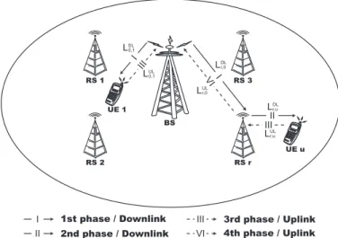
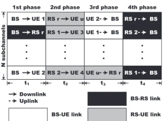
2.1 Network scenario for the four-phase bidirectional relay-based OFDMA system. . . 6 2.2 Timing diagram of the four-phase transmission for
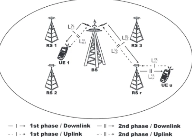
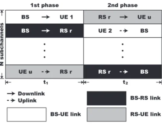
bidirec-tional relay-based OFDMA system. . . 7 3.1 Network scenario for the two-phase bidirectional relay-based
OFDMA system. . . 17 3.2 Timing diagram of the two-phase transmission for
bidirec-tional relay-based OFDMA system. . . 18 4.1 CDF of UE’s normalized UL data rate of 4P and
EERA-2P schemes under different numbers of subcarriers per sub-channel Nc with RU Ereq=1 Mbps, RD/U = 1, and w = 1. . . 27
4.2 Performance comparison of original and reallocated EERA-4P scheme: (left plot) power consumption of UEs and (right plot) outage probability of UEs versus UE’s required data rate RreqU E under RD/U = 1 and w = 1. . . 28
4.3 Normalized phase durations (tτ) versus UE’s required data
rate (RreqU E) for EERA-4P scheme (left plot), EERA-2P and EERA-2PNC schemes (right plot) under RD/U = 1, Nc = 1,
4.4 Performance comparison for power consumption of the pro-posed EERA-4P, EERA-2P, and EERA-2PNC schemes versus the UE’s required data rate RreqU E with RD/U = 1, Nc= 1, and
w = 1. . . 32
4.5 Performance comparison between QARA method and pro-posed EERA schemes: power consumption (left plot) and out-age probability of UE (right plot) versus UE’s required data rate RU Ereq under RD/U = 1, Nc= 1, and w = 1. . . 33
4.6 Performance comparison between QARA method and pro-posed EERA schemes: power consumption (left plot) and out-age probability of UE (right plot) versus number of subcarriers per subchannel Nc under RU Ereq = 1 Mbps, RD/U = 1, and w = 1. 34
4.7 Performance comparison between QARA method and pro-posed EERA schemes: power consumption (left plot) and out-age probability of UE (right plot) versus weighting factor w under RreqU E = 1 Mbps, RD/U = 1, and Nc= 1. . . 35
4.8 Performance comparison between QARA method and pro-posed EERA schemes: power consumption (left plot) and out-age probability of UE (right plot) versus DL-to-UL ratio of UE’s required data rate RD/U under RreqU E = 1 Mbps, Nc = 1,
Chapter 1
Introduction
The orthogonal frequency-division multiple access (OFDMA) [1] is consid-ered a key transmission technology for next generation wireless communica-tion systems, including the worldwide interoperability for microwave access (WiMAX) [2] and the downlink (DL) of 3GPP long term evolution (LTE) [3]. The OFDMA technology is a multiuser version of the orthogonal frequency-division multiplexing (OFDM) technique, which divides the wideband chan-nel into numerous subchanchan-nels in order to both provide high spectral effi-ciency and alleviate frequency-selective fading. Based on the OFDMA tech-nique, multiuser diversity can be achieved by opportunistic scheduling which appropriately allocates the subsets of subchannels to individual user equip-ment (UE). However, the quality-of-service (QoS) requireequip-ments cannot al-ways be guaranteed since the UEs may inevitably be assigned to operate under a worse channel condition. In order to alleviate the severe path loss within a channel, the relay station (RS) is introduced to provide an alterna-tive path between the base station (BS) and the UEs for increasing the spatial coverage of a cell. Therefore, it is important to provide feasible resource al-location for the relay-enhanced communications to improve the throughput,
energy consumption, and outage performance of the system.
Existing research work has been conducted to investigate the resource allocation and power control mechanisms for the OFDM [4; 5] and OFDMA [6–9] networks. However, these mechanisms cannot be directly applied to the networks with the assistance of RS. In order to evaluate the relay-based system including the conventional direct communication and the relay trans-mission in terms of the network throughput, the work presented in [10–18] develops resource allocation strategies in the DL relay-based OFDMA net-works under different assumptions. Noted that each subchannel is partitioned into two transmission phases for the relay-enhanced network, including the first phase to allocate the transmission between the BS and RS and the second phase for the RS and UE. The work in [10] focuses on subchannel assignment and path selection by comparing the effective data rates of the RS and the direct transmissions. A void filling algorithm is proposed in [11] as a heuristic joint path selection and subchannel allocation scheme for throughput enhancement. However, these two schemes are designed with constant power allocation for the UEs. With the QoS consideration, the suboptimal solutions are obtained by jointly considering the subchannel and power allocation for the relay-based network [12]. The work presented in [13] proposes the QoS aware resource allocation (QARA) scheme which considers both the direct and relay communications in the network. Furthermore, all the schemes in [10–13] are designed to utilize the same subchannel assign-ment in both transmission phases for each UE, i.e., an RS receives the data in the first transmission phase and utilizes the same subchannel to forward the data in the second phase. The heuristic switching assignment between the two transmission phases are considered in [14] for power allocation. Op-portunistic power scheduling is studied in [15; 16], it formulates a stochastic optimization problem to maximize the average sum rate of the system.
How-ever, the QoS constraint has not been addressed in [14; 15]. Moreover, the coexistence of both the direct and relay communications in the network has not been investigated in [12; 14]. The heuristic algorithms are proposed in [17; 18] which adjust the phase duration based on the information of mean channel condition and consequently allocate the subchannels. In the uplink (UL) OFDM access network, the work presented in [19] formulates an opti-mization problem for resource allocation in order to maximize the network throughput. On the other hand, considering both the DL and UL trans-missions, four-phase relaying will be required which additionally include the transmissions from the UE to RS and from the RS to BS. Two-phase bidirec-tional relaying is developed in [20–23] to enhance convenbidirec-tional four-phases relay-based transmissions. Considering the physical layer behaviors with sin-gle UE sceanrio, the network coding technique is investigated in [20–22] which allows the RS to encode the data coming from both the BS and the UE, and the RS will consequently broadcast the encoded data back to the BS and UE in the second phase. Moreover, The work proposed in [23] adopts network-ing codnetwork-ing scheme for optimal resource allocation under the assumption that each subchannel can only be allocated with one UE during both transmission phases.
However, it is noticeable to observe that most of the research focuses on maximization of network throughput from the viewpoint of DL. Since most of UEs in a wireless network are battery-powered, energy efficiency is con-sidered one of principal issues to prolong the lifetime of UE [24]. From the aspect of DL, energy minimization are effective in limiting the intercell in-terference [18]. Considering the different requirements among the UEs, RSs, and BS for power consumption, the time durations of the different relaying phases should not be equal owing to the channel variations and various traffic loads between DL and UL. In this thesis, the minimization of total energy
consumption for the network is investigated based on the bidirectional relay-based OFDMA systems. The energy-efficient resource allocation scheme for four-phase (EERA-4P) bidirectional relaying is proposed to solve the opti-mization problem in order to achieve optimal subchannel assignment, power allocation, and phase duration assignment. Based on the pre-defined target data rate as the QoS requirement for each UE, the EERA-4P scheme is de-signed to fully consider various network scenarios including both the DL and UL links, the co-existence of direct and relay communications, and different UE assignments for each phase duration. Owing to the NP-hard nature of the optimization problem for resource allocation, the Lagrangian formulation is adopted to obtain the suboptimal solution based on the continuous relax-ation [25] for subchannel assignment. Furthermore, considering that the UL and DL transmissions can be applied within the same phase duration, the proposed EERA-4P scheme can be simplified to the two-phase scenario, de-noted as EERA-2P scheme, in order to increase the multiuser diversity. The performance of proposed EERA-2P scheme can further be improved with the adoption of network coding technique, which is represented as the EERA-2PNC scheme. Simulation results show that the proposed EERA schemes can provide better energy conservation and outage performance compared to the existing relay-based resource allocation scheme with the considerations of QoS requirements.
The rest of this thesis is organized as follows. In Chapter 2, the system model and the formulation of proposed EERA-4P scheme are presented. The EERA-2P and EERA-2PNC schemes are further discussed in Chapter 3. Performance evaluation and comparison of proposed schemes are conducted in Chapter 4 via simulations. Chapter 5 draws the conclusions.
Chapter 2
Proposed Energy-Efficient
Resource Allocation Scheme for
Four-Phase (EERA-4P)
Bidirectional Relaying
2.1
System Model and Problem Formulation
As shown in Fig. 2.1, a scenario of four-phase bidirectional relay-enhanced OFDMA system is depicted. There exists a BS, R fixed RSs, and U UEs in a single cellular network. The entire channel bandwidth is equally divided into N subchannels, where each subchannel with B Hz is composed of Nc
adjacent subcarrier. In this thesis, Nc = 1 is considered in the proposed
EERA schemes for simplicity of problem formulation. Note that Nc can be
extended to any value without modifying the original formulation of EERA schemes, which will be discussed in the performance evaluation chapter. Be-fore the DL process, the BS can obtain all the channel state information,
UE 1 BS RS 1 RS 2 RS 3 RS r UE u I VI I III II III 1st phase / Downlink
I III 3rd phase / Uplink
2nd phase / Downlink II VI 4th phase / Uplink LDL r,0 LUL r,0 LDL r,u LUL r,u LDL 0,1 LUL 0,1
Figure 2.1: Network scenario for the four-phase bidirectional relay-based OFDMA system.
e.g., the channel gain, of both the RSs and UEs based on their correspond-ing feedback mechanism. It is also assumed that the channel gains of all the communication links remain constant in one frame. Based on the chan-nel state information, the target data rate for each UE is pre-specified by a scheduler within the BS which is served as the QoS requirement for each UE. With the adoption of half-duplex antennas, four phases are required for the relay-based communication in order to complete both the DL and UL data transmissions. Let S→D be denoted as the transmission from source S to destination D, where S, D∈{BS, RS, UE}. As illustrated in Fig. 2.1, the first phase of each subchannel can be allocated with either a BS→RS transmission or a BS→UE transmission, and that of the second phase is assigned with an RS→UE transmission. On the other hand, for the UL transmissions, the third phase is allocated with either a UE→BS or UE→RS; while an RS→BS is assigned for the fourth phase. Note that the BS→UE and UE→BS repre-sent direct communications between the BS and UE where the RSs are not involved in the transmission. Each phase of a subchannel is only allowed to
BS RS r BS UE 1 BS UE 2 Ά! Ά! Ά! RS 1 UE 3 RS r UE u RS 2 UE 4 Ά! Ά! Ά! UE 1 BS UE 2 BS UE u RS r Ά! Ά! Ά! RS 2 BS RS r BS RS 1 BS Ά! Ά! Ά! 1st phase 2nd phase 3rd phase 4th phase
BS-UE link BS-RS link RS-UE link N s ubc hannels Downlink Uplink ! t1 t2 t3 t4
Figure 2.2: Timing diagram of the four-phase transmission for bidirectional relay-based OFDMA system.
allocate one communication link, and the parameter tτ is defined as the time
duration of the τ th phase, for τ = 1, 2, 3 and 4, as shown in Fig. 2.2. As illustrated in Fig. 2.1, the parameter Ll
r,uindicates the communication
link between RS r and UE u where l ∈ {DL, UL}, r ∈ {1, . . . , R}, and
u ∈ {1, . . . , U }. Note that R and U respectively represent the maximum
numbers of RS and UE in the network, and the superscript l describes the transmission direction. Ll
0,u denotes the link between the BS and UE u by
assigning the subscript r = 0, and Ll
r,0 is the link between BS and RS r with
the subscript u = 0. Md and Mr denote the sets of UEs that are operated
in direct and relay-assisted mode, respectively, i.e., u ∈ Md or u ∈ Mr, ∀u.
The relay selection function Ω(u) is defined as Ω(u) = r if a UE u is served by the RS r, i.e., u ∈ Mr; while Ω(u) = 0 if a UE u is operated in direct
mode, i.e., u ∈ Md. Moreover, ρn,lr,u ∈ {0, tτ} for τ = 1, 2, 3 and 4 denotes the
subchannel assignment indicator for Ll
r,u on the τ th phase of subchannel n
as either assigned (ρn,l
where Φ4 τ = {(l, r, u)|(l = DL, r = Ω(u), u ∈ Md) or (l = DL, r 6= 0, u = 0)}, if τ = 1, {(l, r, u)|l = DL, r = Ω(u), u ∈ Mr}, if τ = 2,
{(l, r, u)|(l = UL, r = Ω(u), u ∈ Md) or (l = UL, r = Ω(u), u ∈ Mr)}, if τ = 3,
{(l, r, u)|l = UL, r 6= 0, u = 0}, if τ = 4, (2.1)
The set Φ4
τ in (2.1) denotes the set of communication links transmitting in
the τ th phase where the superscript 4 indicates the case of four-phase bidi-rectional relaying. Let pn,l
r,u be defined as the transmission power of Llr,uin the
corresponding phase determined by ρn,l
r,u of the subchannel n, the normalized
data rate Cn,l
r,u of Llr,u on subchannel n can be acquired as
Cn,l
r,u = ρn,lr,ulog(1 + pn,lr,ugr,un ), (2.2)
where gn r,u = |Hn r,u|2 ΓBN0 with H n
r,u as the channel gain of Llr,u in subchannel n
and N0 denting the power spectral density of additive white Gaussian noise
(AWGN). The parameter Γ = − ln(5BER)/1.5 is obtained from [26] given the target bit error rate BER and the continuous-rate M-ary quadrature amplitude modulation. Based on the normalized data rate Cn,l
r,uobtained from
(2.2), an optimization problem with the objective to minimize the weighted energy consumption of the entire system can be formulated as
min (ρ,p,t) 4 X τ =1 wτ XN n=1 X (l,r,u)∈Φ4 τ pn,l r,u· tτ (2.3a) s. t. ρn,l r,u ∈ {0, tτ}, ∀n, ∀(l, r, u) ∈ Φ4τ, ∀τ ∈ {1, 2, 3, 4}; (2.3b) N X n=1 Ã X u∈Md pn,DL0,u + R X r=1 pn,DLr,0 ! ≤ Pmax BS ; (2.3c)
N X n=1 X u∈Mr pn,DL r,u ≤ PRSmax, N X n=1 pn,U Lr,0 ≤ Pmax RS , ∀r; (2.3d) N X n=1
pn,U LΩ(u),u ≤ PU Emax, ∀u; (2.3e)
X (l,r,u)∈Φ4 τ ρn,l r,u ≤ tτ, ∀n, ∀τ ; (2.3f) 4 X τ =1 tτ = 1; (2.3g) N X n=1 Cn,l
r,u ≥ Rreq,lr,u , ∀(l, r, u) ∈ Φ4τ, ∀τ, (2.3h)
where the parameter ρ, p, and t are defined as the sets of ρn,l
r,u, pn,lr,u, and
tτ respectively for all values of n, (l, r, u) ∈ Φ4τ, and τ . In other words, the
optimal subchannel assignment ρn,l
r,u for link Llr,u, power allocation pn,lr,u, and
phase duration tτ can be obtained in order to minimize the system energy
consumption as defined in (2.3a). The expression in (2.3b) states that each communication link can be either assigned with a subchannel, i.e., ρn,l
r,u = tτ,
or not assigned, i.e., ρn,l
r,u = 0. The constraints in (2.3c)-(2.3e) respectively
ensure that transmission power of the BS, RS, and UE cannot exceed its corresponding maximum transmission power, i.e., Pmax
BS , PRSmax, and PU Emax.
(2.3f)-(2.3g) are respectively utilized to denote that each phase duration tτ
of a subchannel can only be allocated with at most one communication link, and the summation of all tτ is normalized to be one. The condition in (2.3h)
indicates that each UE and RS is required to achieve its target data rate, where the parameter Rreq,l
r,u represents the required data rate of link Llr,u
according to its QoS requirement.
Moreover, the weighting factors wτ in (2.3a) denotes the relative weights
to notice that only the third phase corresponds to the transmissions that originated from the UEs, i.e., either from UE to BS or from UE to RS. Since the maximum transmission power of UE is much less than that of the BS and RS in general, the communication links UE→RS and UE→BS are always considered the bottlenecks for the relay-based networks. Therefore, it is required to investigate the energy consumption of UEs with respect to that of the entire network in order to evaluate different effects to the system performance. The weighting factors can consequently be assigned as [w1, w2, w3, w4] = [1, 1, w, 1], where the influence from w to the system outage
probability will be evaluated in the performance evaluation chapter.
It can be observed that the optimization problem in (2.3) is a mixed integer programming problem. It is in general considered as an NP-hard problem, which does not exist efficient algorithm to acquire the optimal so-lution except by adopting the exhausted search algorithm. The major reason for (2.3) not being considered as a convex optimization problem is mainly due to the discrete manner of the subchannel assignment indicator ρn,τ
r,u, which
can only be assigned with either tτ or 0 value. In the case that the constraint
can be released as stated in [25], i.e., by allowing the indicator ρn,τ r,u to be
any value within the interval [0, tτ], the original optimization problem can be
converted into a convex optimization problem. Consequently, the objective of this thesis becomes to seek for a suboptimal solution for resource alloca-tion by adopting a methodology with lower complexity. Let εn,l
r,u be defined
as the effective transmission energy as εn,l
r,u = pn,lr,uρn,lr,u, the normalized data
rate Cn,l
r,u of Llr,u in (2.2) can be rewritten as
Cn,l
r,u = ρn,lr,ulog
à 1 + ε n,l r,ugr,un ρn,lr,u ! . (2.4)
Let ε be defined as the set of εn,l
set (ρ, p, t) in (2.3a) is replaced by (ρ, ε, t), and the equations from (2.3a) to (2.3e) are respectively modified as
min (ρ,ε,t) N X n=1 X τ =1,2,4 X (l,r,u)∈Φ4 τ εn,l r,u+ w X (l,r,u)∈Φ4 3 εn,l r,u (2.5a) s. t. ρn,l r,u ∈ [0, tτ], ∀n, ∀(l, r, u) ∈ Φ4τ, ∀τ ∈ {1, 2, 3, 4}; (2.5b) N X n=1 Ã X u∈Md εn,DL0,u + R X r=1 εn,DLr,0 ! ≤ t1PBSmax; (2.5c) N X n=1 X u∈Mr εn,DL r,u ≤ t2PRSmax, N X n=1 εn,U Lr,0 ≤ t4PRSmax, ∀r; (2.5d) N X n=1
εn,U LΩ(u),u ≤ t3PU Emax, ∀u. (2.5e)
The objective function defined in (2.5a) is equivalent to the energy con-sumption from both the BS and the RSs plus the weighted energy consump-tion from the UEs. Note that (2.5b) is different from (2.3b) where [0, tτ] in
(2.5b) represents a continuous interval between 0 and tτ and the set {0, tτ}
in (2.3b) only contains two elements, i.e., 0 and tτ. As a result, the
optimiza-tion problem for resource allocaoptimiza-tion in (2.3) can be converted into a convex optimization problem by replacing (2.3a)-(2.3e) with (2.5a)-(2.5e).
2.2
Proposed EERA-4P Scheme
In this section, the proposed EERA-4P scheme will be designed to allocate subchannels, transmission power, and phase duration in order to minimize weighted transmission energy of the system. Each subchannel will be accom-modated with different UEs or RSs at the four transmission phases. The modified optimization problem in (2.3) along with the convex properties as
in (2.5a)-(2.5e) can be formulated as a Lagrangian function. Let λ1, λ2,r,
λ3,u, and λ4,r be defined as the Lagrangian multipliers for the constraints in
(2.5c)-(2.5e). The parameters ητ,n and µlr,u are the Lagrangian multipliers of
the constraint in (2.3f) and the QoS constraint of Ll
r,u in (2.3h), respectively.
Moreover, Λ is defined as the set of all Lagrangian multipliers. Hence, the Lagrangian function L(ρ, ε, t, Λ) can be expressed as
L(ρ, ε, t, Λ) = N X n=1 X τ =1,2,4 X (l,r,u)∈Φ4 τ εn,l r,u+ w N X n=1 X (l,r,u)∈Φ4 3 εn,l r,u + λ1 " N X n=1 à X u∈Md εn,DL0,u + R X r=1 εn,DLr,0 ! − t1PBSmax # + R X r=1 λ2,r N X n=1 X u∈Mr} εn,DL r,u − t2PRSmax + U X u=1 λ3,u à N X n=1
εn,U LΩ(u),u− t3PU Emax
! + R X r=1 λ4,r à N X n=1 εn,U Lr,0 − t4PRSmax ! + 4 X τ =1 N X n=1 ητ,n X (l,r,u)∈Φ4 τ ρn,lr,u− tτ − 4 X τ =1 X (l,r,u)∈Φ4 τ µlr,u à N X n=1
Cr,un,l− Rreq,lr,u
!
.
(2.6) Moreover, the Karush-Kuhn-Tucker conditions for obtaining the optimal so-lution are ∂L(ρ, ε, t, Λ) ∂εn,lr,u ( ≥ 0, if εn,l r,u = 0, = 0, if εn,l r,u > 0. (2.7a) ∂L(ρ, ε, t, Λ) ∂ρn,lr,u ( ≥ 0, if ρn,l r,u = 0, = 0, if ρn,l r,u > 0. (2.7b) ∂L(ρ, ε, t, Λ) ∂tτ ( ≥ 0, if tτ = 0, = 0, if tτ > 0. (2.7c)
Equation (2.7a) can further be expressed as ∂L(ρ, ε, t, Λ) ∂εn,lr,u = λl r,u− µl
r,uρn,lr,ugnr,u
ρn,lr,u+ gnr,uεn,lr,u
, (2.8) where λl r,u = 1 + λ1, if (l, r, u) ∈ Φ41, 1 + λ2,r, if (l, r, u) ∈ Φ42, w + λ3,u, if (l, r, u) ∈ Φ43, 1 + λ4,r, if (l, r, u) ∈ Φ44. (2.9)
Note that the parameter λl
r,u in (2.9) is equivalent to the weighting factor
plus the corresponding Lagrangian multiplier. Therefore, according to (2.7a) and (2.8), the effective transmission energy εn,l
r,u can be written as
εn,l r,u = ρn,lr,u à µl r,u λl r,u − 1 gn r,u !+ . (2.10)
It is noted that the expression (x)+ in (2.10) indicates (x)+= x if x ≥ 0 and
(x)+ = 0 if x < 0, and the factor µlr,u
λl
r,u is similar to the concept of conventional
water level. Furthermore, equation (2.7b) can also be similarly derived as
∂L(ρ, ε, t, Λ) ∂ρn,lr,u = ητ,n− µlr,u " log à 1 + ε n,l r,ugnr,u ρn,lr,u ! − ε n,l r,ugr,un
ρn,lr,u+ εn,lr,ugnr,u
#
. (2.11)
By substituting (2.11) into (2.10), the function Dn,l
r,u can be defined and
ob-tained as Dn,l r,u = µlr,u " log à 1 + ε n,l r,ugnr,u ρn,lr,u ! − ε n,l r,ugnr,u
ρn,lr,u+ εn,lr,ugnr,u
= µlr,u "Ã log(µ l r,ugr,un λl r,u ) !+ − Ã 1 − λ l r,u µl r,ugr,un !+# ( ≤ ητ,n, if ρn,lr,u = 0, = ητ,n, if ρn,lr,u > 0. (2.12) According to the definition of normalized data rate Cn,l
r,u as in (2.2), it can be
observed from (2.12) that Dn,l
r,u is positively related to the data rate of link
Ll
r,u on subchannel n. Based on [27], given the ˆnth subchannel and the ˆτ th
transmission phase, there exists a link Ll∗
r∗,u∗ such that (l∗, r∗, u∗) = arg max (l,r,u)D ˆ n,l r,u, ∀(l, r, u) ∈ Φ4τˆ. (2.13)
If there exists a unique Ll∗
r∗,u∗ to achieve the maximal value of Dn,lr,u, the
optimal resource allocation can be obtained such that
ρn,lrˆ∗,u∗∗ = tτˆ, ρr,un,lˆ = 0, ∀(l, r, u) ∈ Φ4ˆτ and (l, r, u) 6= (l∗, r∗, u∗). (2.14)
As mentioned before, the subchannel assignment indicator is relaxed from the original two distinct values, i.e., ρn,l
r,u ∈ {0, tτ}, into a continuous set of
values in the interval of [0, tτ]. Therefore, the resulting optimal solution can
happen if the indicator ρn,l
r,u is a value between [0, tτ]. In such case, suboptimal
and non-unique solutions with link Ll∗
r∗,u∗ that satisfy (2.14) can be acquired
by constraining ρn,l
r,u to be either 0 or tτ. As a result, the τ th phase of nth
subchannel will be assigned with the link that has largest value of Dn,l r,u. The
resource allocation for all the subchannels and phases can also be determined in a similar manner.
Moreover, in order to obtain the suboptimal solution for (2.14), the values of the Lagrangian multipliers and tτ are required to be obtained. An iterative
approach that exploits the subgradient method as in [28] is utilized to update the value of each Lagrangian multiplier and tτ. For example, considering
that λ(i)1 , µl,(i)r,u , and t(i)1 are defined as the ith iteration of λ1, µlr,u, and t1
respectively, their updating process can be expressed as
λ(i+1)1 = Ã λ(i)1 + s(i) Ã N X n=1 (X u∈M1 εn,DL0,u + R X r=1 εn,DLr,0 ) − t(i)1 PBSmax !!+ , (2.15) µl,(i+1) r,u = Ã µl,(i) r,u + s(i) Ã Rreq,l r,u − N X n=1 Cn,l r,u !!+ , (2.16) t(i+1)1 = Ã t(i)1 − s(i) Ã N X n=1 η4,n(i) − N X n=1 η1,n(i) + Pmax RS R X r=1 λ(i)4,r− Pmax BS λ (i) 1 !!+ , (2.17) where s(i) = α/√i is the step size and α is a tunable constant. Note that
(2.17) is obtained by assigning t4 = 1 − t1− t2− t3 according to (2.3g). The
updating processes for the other Lagrangian multipliers can also be obtained similarly. It is also notice from (2.16) that the update process of µl
r,u reflects
the capability of achieving the QoS requirement for each UE. In the case that a UE has difficulty to reach the required data rate Rreq,l
r,u , a larger value of µlr,u
will be obtained after the subgradient iterations. This result can also be uti-lized to explain the reason for the function Dn,l
r,u to be positively related to µlr,u
as shown in (2.12). In addition to achieving the required data rate for each UE, the optimization problem presented in (2.13) also intends to increase the multiplier µl
r,u for those UEs that has difficulty to achieve their QoS
require-ments. In summary, the power allocation, subchannel assignment, and phase duration for the four-phase relay network can be determined by the proposed EERA-4P scheme according to (2.10), (2.14), and (2.17), respectively.
Chapter 3
Proposed Energy-Efficient
Resource Allocation Schemes
for Two-Phase (EERA-2P)
Bidirectional Relaying
3.1
System Model and Problem Formulation
In this chapter, the network scenarios with two-phase bidirectional relaying is considered for energy-efficient resource allocation. In the case that both the DL and UL links can be allocated within the same transmission phase, the original four-phase transmission can be simplified into the two-phase case as shown in Fig. 3.1. Two different resource allocation schemes are considered in this chapter which includes the EERA-2P and the EERA-2PNC mechanisms, and will be explained as follows.
UE 1 BS RS 1 RS 2 RS 3 RS r UE u I II I II I II 1st phase / Downlink I II 2nd phase / Downlink 1st phase / Uplink I II 2nd phase / Uplink LDL r,0 LUL r,0 LDL r,u LUL r,u LDL 0,1 LUL 0,1
Figure 3.1: Network scenario for the two-phase bidirectional relay-based OFDMA system.
3.2
Proposed EERA-2P Scheme
As illustrated in Fig. 3.2, each of the τ th phase has the time duration of
tτ and a subchannel in a transmission phase is allocation with one
commu-nication link. The first phase of each subchannel can be allocated to either BS→UE, BS→RS, or UE→RS links; while that for the second phase is as-signed to UE→BS, RS→BS, or RS→UE. It is intuitive to observe that the two-phase bidirectional relaying may outperform the original four-phase case since there exists more freedom for subchannel assignment. In other words, it is not necessary for the communication links to be partitioned into either DL or UL for subchannel assignment as is required in the four-phase bidi-rectional relaying case. In the proposed EERA-2P scheme, the set Φ2
τ which
t1 BS RS r BS UE 1 UE u RS r Ά! Ά! Ά! UE 2 BS RS r UE u RS r BS Ά! Ά! Ά! 1st phase 2nd phase BS-UE link BS-RS link RS-UE link N s ubc hannels Downlink Uplink t2
Figure 3.2: Timing diagram of the two-phase transmission for bidirectional relay-based OFDMA system.
bidirectional relaying can be defined as
Φ2τ = {(l, r, u)| (l = DL, r = 0, u ∈ Md) or (l = DL, r 6= 0, u = 0) or (l = UL, r = Ω(u), u ∈ Mr)}, if τ = 1,
{(l, r, u)| (l = DL, r = Ω(u), u ∈ Mr) or (l = UL, r = 0, u ∈ Md)
or (l = UL, r 6= 0, u = 0)}, if τ = 2.
(3.1) Consequently, the optimization problem of minimizing the weighted system energy for the EERA-2P scheme can be expressed as
min (ρ,ε,t) 2 X τ =1 N X n=1 X (l,r,u)∈Φ2 τ εn,l r,u+ (w − 1) N X n=1 U X u=1
εn,U LΩ(u),u (3.2a)
s. t. ρn,l r,u ∈ [0, tτ], ∀n, ∀(l, r, u) ∈ Φ2τ, ∀τ ∈ {1, 2}; (3.2b) N X n=1 (X u∈Md εn,DL0,u + R X r=1 εn,DLr,0 ) ≤ t1PBSmax; (3.2c)
N X n=1 (X u∈Mr εn,DL
r,u + εn,U Lr,0 ) ≤ t2PRSmax, ∀r; (3.2d)
N
X
n=1
εn,U LΩ(u),u ≤ t1PU Emax, ∀u ∈ Mr; N
X
n=1
εn,U L0,u ≤ t2PU Emax, ∀u ∈ Md;
(3.2e) X (l,r,u)∈Φ2 τ ρn,l r,u ≤ tτ, ∀n, ∀τ ; (3.2f) 2 X τ =1 tτ = 1; (3.2g) N X n=1
Cr,un,l ≥ Rreq,lr,u , ∀(l, r, u) ∈ Φ2τ, ∀τ. (3.2h)
With the mixed DL/UL subchannel assignment in the two transmission phases, the original objective function (2.5a) will be revised into (3.2a) for minimization of system energy. It corresponds to the situation of minimiz-ing the total energy consumption from BS, RSs, and UEs with additional weighting factor (w − 1) of the energy consumption from the UEs. Note that the power constraints defined from (3.2c) to (3.2e) for the EERA-2P scheme are revised from (2.5c) to (2.5e) in the EERA-4P scheme for BS, RSs, and UEs, respectively. (3.2f) and (3.2h) in the EERA-2P scheme are respectively modified from (2.3f) and (2.3h) in the EERA-4P scheme as the constraints for subchannel assignment and QoS requirement. Similar to the procedures presented in Section 2.2, the original optimization problem for the EERA-2P scheme can be transformed into the suboptimal formulation based on Lagrangian function. The parameter λl
will become λl r,u = 1 + λBS, if (l = DL, r = 0, u ∈ Md) or (l = DL, r 6= 0, u = 0),
w + λU E,u, if (l = UL, r = 0, u ∈ Md) or (l = UL, r = Ω(u), u ∈ Mr),
1 + λRS,r, if l = DL, r = Ω(u), u ∈ Mr,
1 + λRS,r, if l = UL, r 6= 0, u = 0,
(3.3) where λBS, λRS,r, and λU E,u are Lagrangian multipliers of (3.2c), (3.2d),
and (3.2e), respectively. Compared to λl
r,u as obtained from (2.9) for the
EERA-4P scheme, the parameter λl
r,u acquired in (3.3) for the EEEA-2P
scheme requires additional conditions to specify the designated cases since there only exist two phases to allocate the transmission links. Similarly, the value of subchannel assignment ρn,l
r,uwill be relaxed from the distinct values of
{0, tτ} for τ = 1, 2 into a continuous interval of [0, tτ] in order to convert the
original formulation into a convex optimization problem. The subgradient method will be employed to provide the updating process of the Lagrangian multipliers and the phase duration tτ. As a results, the power allocation,
subchannel assignment, and phase duration can be obtained by adopting the EERA-2P scheme for the two-phase relaying networks.
3.3
Proposed EERA-2P with Network
Cod-ing (EERA-2PNC) Scheme
By adopting the networking coding technique, the EERA-2PNC scheme is designed to further improve the performance of the EERA-2P algorithm for the two-phase bidirectional relaying networks. The concept of network cod-ing is utilized by the RS to combine both the DL and UL data transmissions
together into a single transmission for the corresponding receivers. For in-stance, it is considered that RS r is in charge of relaying data packets for both the BS and UE u. If u possesses a UL packet PU L for the BS and
the BS has a DL packet PDL for u, they will separately transmit the packet
to the RS r on different subchannels in the first transmission phase. In the second phase, by adopting the network coding scheme, the RS r will deliver the packet Pnc = PU L⊕ PDL to both the BS and UE u on an
identi-cal subchannel, where ⊕ represents the exclusive or operation. Afterwards, the BS receives the combined packet Pnc and will perform the operation of
Pnc⊕ PDL = (PU L⊕ PDL) ⊕ PDL = PU L, which can consequently obtain the
packet PU L initiated from UE u. Similar operation will also be executed by
u, i.e., Pnc ⊕ PU L = (PU L⊕ PDL) ⊕ PU L = PDL, in order to acquire PDL
transmitted from the BS.
Note that the RS r will deliver the combined packet Pnc with the lower
data rate which is limited by both the RS→UE and the RS→BS communi-cation links. Consequently, the link LDU
r,u for r = Ω(u) and u ∈ Mr is defined
for transmitting the network coded packets according to the links RS r → BS and RS r →UE u. If an RS r is transmitting data packet via the LDU r,u
link on a subchannel n, it represents that r is delivering a combined packet
Pnc to both the UE u and the BS. Furthermore, it is considered that the
equivalent channel gain gn,DU
r,u of link LDUr,u on the subchannel n is determined
as min(gn
r,0, gr,un ). The set Φ2,ncτ which consists of all communication links in
the τ th phase for the proposed EERA-2PNC scheme can be defined as
Φ2,nc τ = ( {(l, r, u)| (l, r, u) ∈ Φ2 1}, if τ = 1, {(l, r, u)| (l, r, u) ∈ Φ2 2 or (l = DU, r = Ω(u), u ∈ Mr)}, if τ = 2. (3.4) where Φ2
and second phases as defined in (3.1) for the EERA-2P scheme. It can be observed that both the EERA-2P and EERA-2PNC schemes share the same types of communication links in the first phase; while additional network coded link is included in the second phase of EERA-2PNC method. The optimization problem of minimizing weighted energy for the EERA-2PNC scheme can be formulated as
min (ρ,ε,t) 2 X τ =1 N X n=1 X (l,r,u)∈Φ2,ncτ εn,lr,u+ (w − 1) N X n=1 U X u=1
εn,U LΩ(u),u (3.5a)
s. t. ρn,l r,u ∈ [0, tτ], ∀n, ∀(l, r, u) ∈ Φ2,ncτ , ∀τ ∈ {1, 2}; (3.5b) N X n=1 (X u∈Md εn,DL0,u + R X r=1 εn,DLr,0 ) ≤ t1PBSmax; (3.5c) N X n=1 " X u∈Mr ¡
εn,DLr,u + εn,DUr,u ¢+ εn,U Lr,0 #
≤ t2PRSmax, ∀r; (3.5d)
N
X
n=1
εn,U LΩ(u),u ≤ t1PU Emax, ∀u ∈ Mr; N
X
n=1
εn,U L0,u ≤ t2PU Emax, ∀u ∈ Md;
(3.5e) X (l,r,u)∈Φ2,ncτ ρn,lr,u ≤ tτ, ∀n, ∀τ ; (3.5f) 2 X τ =1 tτ = 1; (3.5g) N X n=1
Cr,un,l ≥ Rreq,lr,u , ∀(l, r, u) ∈ Φ2,nc1 ; (3.5h)
N
X
n=1
C0,un,U L ≥ Rreq,U L0,u , ∀u ∈ Md; (3.5i)
N
X
n=1
³
CΩ(u),un,DL + CΩ(u),un,DU ´
N X n=1 Ã Cr,0n,U L+ X u∈Mr Cn,DU r,u ! ≥ Rreq,U Lr,0 , ∀r. (3.5k)
It can be seen that the power constraints for both the BS in (3.5c) and the UE in (3.5e) is the same as that for the EERA-2P scheme; while that for the RS in (3.5d) additional considers the energy consumption for the network coded link εn,DU
r,u in the constrained equation. The QoS constraints in (3.5h)-(3.5k)
are extended from (3.2h) in order to fully consider the QoS requirement for the EERA-2PNC scheme with the network coded links, which are specifi-cally addressed in (3.5j) and (3.5k) for the RS→UE and the RS→BS links respectively. Moreover, the parameter λl
r,u for the EERA-2PNC scheme can
be obtained as
λlr,u = (
1 + λRS,r, if l = DU, r = Ω(u), u ∈ M2,
(3.3), otherwise, (3.6)
which additional consider the case with network coded links other than the original λl
r,u defined in (3.3) for the EERA-2P scheme. The Lagrangian
multiplier of the QoS constraint µl
r,ufor the EERA-2PNC scheme is redefined
as
µl r,u ←
(
µU L
r,0 + µDLr,u, if l = DU, r = Ω(u), u ∈ M2,
µl
r,u, otherwise.
(3.7)
Note that the resulting parameter µDU
r,u in (3.7) is a combination of Lagrangian
multipliers, i.e., µDU
r,u = µU Lr,0 + µDLr,u, considering the case with network coded
packets. By substituting the corresponding values of λl
r,u and µlr,u into (2.12),
the EERA-2PNC scheme can determine the feasible channel n to be assigned for the link Ll
r,u. It is intuitive to observe the benefit of proposed
DL links with a single transmission of the combined packet, which can result in higher water level as µU Lr,0+µDLr,u
λDU
r,u compared to the original EERA-2P scheme.
However, since the channel gain for transmitting the combined packets will be limited by min(gn
r,0, gr,un ), the packet that originally can be transmitted with
link under higher channel gain will be sacrificed and only be delivered at lower data rate. Based on the formulation of proposed EERA-2PNC scheme, instead of adopting the networking coding technique, pure DL or UL packet may be transmitted if there exists large difference between the values of gn
r,0
and gn
r,ufor channel n. In order to clearly observe the behaviors of the various
techniques, performance comparison among the proposed EERA schemes will be conducted in the next chapter.
Chapter 4
Performance Evaluation
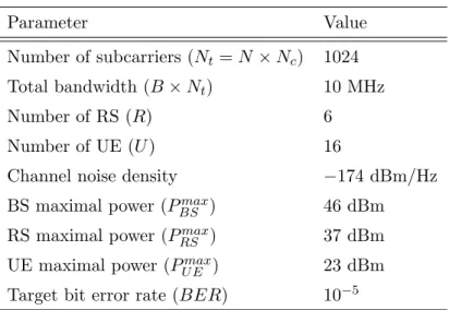
Simulations are performed to evaluate the performance of proposed EERA-4P, EERA-2P, and EERA-2PNC schemes in comparison with the QARA algorithm [13]. The QARA scheme is designed to consider equal two-phase durations for each subchannel for the DL transmissions in order to maximize the network throughput. For fair comparison, the original QARA is mod-ified with the target of minimizing energy consumption with both UL and DL traffic considered. The network scenario is described as follows. A BS is located at the center of the cell which confines a circular region with radius equal to 1500 meters. The UEs are randomly distributed within the trans-mission range of BS. Fixed RSs are designed to be uniformly located around the BS where the distance to the BS is 2/3 of the cell radius. The path loss and small-scale fading models are adopted from [29; 30] to consider the multi-path effect. The BS-RS links are considered line-of-sight (LOS) with a Rician factor K of 10 as utilized in [31], and the RS-UE and BS-UE links are Non-LOS signals with different path loss exponents. The values of sim-ulation parameters are shown in Table 1. The observation and adjustment of proposed schemes will be presented in Section 4.1; while the performance
comparison will be illustrated in Section 4.2.
TABLE 1 : SYSTEM PARAMETERS
Parameter Value
Number of subcarriers (Nt= N × Nc) 1024
Total bandwidth (B × Nt) 10 MHz
Number of RS (R) 6
Number of UE (U ) 16
Channel noise density −174 dBm/Hz
BS maximal power (Pmax
BS ) 46 dBm
RS maximal power (Pmax
RS ) 37 dBm
UE maximal power (PU Emax) 23 dBm
Target bit error rate (BER) 10−5
4.1
Observations and Adjustment of Proposed
Suboptimal EERA Schemes
In order to verify the effectiveness of EERA schemes, detail mechanisms within the proposed schemes will be observed and adjusted by simulating both the UL and DL traffic in the networks. Note that all UEs are designed to possess identical required DL data rate Rreq,DLΩ(u),u and UL data rate Rreq,U LΩ(u),u, and the ratio between the required DL and UL traffic is defined as RD/U=
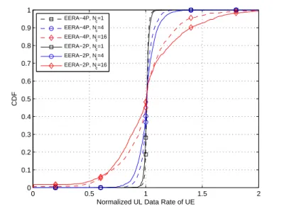
Rreq,DLΩ(u),u/Rreq,U LΩ(u),u. Moreover, the parameter RreqU E which is the summation of required data rate for a UE is defined as RreqU E = Rreq,DLΩ(u),u + Rreq,U LΩ(u),u. Since the UE’s UL traffic is considered critical to influence the network performance, the cumulative distribution function (CDF) of UE’s UL data rate is shown in Fig. 4.1. The UE’s data rate is normalized by the required UL data rate for UEs Rreq,U LΩ(u),u. Both the proposed EERA-4P and EERA-2P schemes are performed under different numbers of subcarriers per subchannel Nc with
0 0.5 1 1.5 2 0 0.1 0.2 0.3 0.4 0.5 0.6 0.7 0.8 0.9 1
Normalized UL Data Rate of UE
CDF EERA−4P, N c=1 EERA−4P, Nc=4 EERA−4P, Nc=16 EERA−2P, Nc=1 EERA−2P, N c=4 EERA−2P, Nc=16
Figure 4.1: CDF of UE’s normalized UL data rate of 4P and EERA-2P schemes under different numbers of subcarriers per subchannel Nc with
RreqU E=1 Mbps, RD/U = 1, and w = 1.
RreqU E = 1 Mbps, RD/U = 1, and w = 1.
As mentioned in Section 2.1, in stead of having the discrete value of either
tτ or 0 for the subchannel assignment indicator ρn,lr,u, it is required to allow ρn,lr,u
to be any value in the range of [0, tτ] in order to preserve the convex property
of the optimal resource allocation problem. By adopting the proposed EERA schemes, suboptimal solution will be obtained by constraining the indicator
ρn,l
r,u to be either tτ or 0 for subchannel assignment. As shown in the Fig. 4.1,
the UL data rate for all the UEs can almost match with the required UL data rate for UEs Rreq,U LΩ(u),u under smaller value of Nc, e.g., Nc= 1. However, as the
value of Nc is increased, each resource block will possess a larger allocatable
range from the frequency domain perspective which consequently results in reduced number of subchannels since N = Nt/Nc. In other words, there will
be less chance for the optimal subchannel assignment indicator ρn,l
0.2 0.4 0.6 0.8 1 0.1 0.2 0.3 0.4 0.5 0.6 0.7 0.8 RreqUE (Mbps)
Total Power Consumption of UEs (W)
0.2 0.4 0.6 0.8 1 0 0.1 0.2 0.3 0.4 0.5 0.6 0.7 RreqUE (Mbps) Outage Probability of UE Original, N c=1 Reallocated, Nc=1 Original, Nc=4 Reallocated, Nc=4 Original, N c=16 Reallocated, N c=16
Figure 4.2: Performance comparison of original and reallocated EERA-4P scheme: (left plot) power consumption of UEs and (right plot) outage prob-ability of UEs versus UE’s required data rate RreqU E under RD/U = 1 and
w = 1.
discrete value of either tτ or 0 since there will exist wider range of value to be
assigned. Therefore, after the suboptimal subchannel assignment, there will be great opportunity for the UEs to have either excessive or insufficient UL data rate compared to the required UL data rate for UEs RΩ(u),ureq,U Lunder larger
Nc values. Compared to the EERA-4P scheme, it can be observed that the
problem becomes more severe for the EERA-2P method since there are less number of resource block, i.e., less number of total subchannels multiplied by the number of phases. There is larger chance for ρn,l
r,u not being assigned
on either tτ or 0.
This problem can be alleviated by conducting a second round of resource allocation. The original EERA schemes will be performed to obtain the suboptimal solution of phase durations, subchannel assignment, and trans-mission power of BS, RSs, and UEs. An additional process of the EERA
schemes will be conducted to reallocate the transmission power of BS, RSs, and UEs under the conditions with fixed subchannel assignment and phase durations that were obtained in the last iteration. This process provides fine-tuning of the proposed EERA schemes by adjusting the transmission power of each network components based on their corresponding QoS con-straints of date rate. For example, in the case that the required rate of a UE is not satisfied, the transmission power of the UE will be increased in the additional process of EERA schemes until the achievable rate is equal its rate requirement or the power consumption of the UE exceeds its power limit. Fig. 4.2 illustrates the comparison between the original and reallo-cated EERA-4P scheme under Nc = 1, 4, and 16. The power consumption
and outage probability of UEs versus the required data rate for UE are shown in the left and right plots, respectively. Note that the outage probability of UEs is defined as 5% of tolerant ratio. In other words, it is categorized as outage if the UE’s power consumption exceeds the maximum transmission power for 5% or the UE’s achievable data rate is less than the required rate for 5%. Due to UE’s limited capability of transmitting power, the UE’s outage probability will possess higher value compared to that of the BS or RSs. Therefore, only the outage probability of UE will be observed in this thesis. As can be seen from Fig. 4.2 that the reallocation procedure reduces both the power consumption and outage probability compared to the origi-nal EERA-4P scheme by adjusting the transmission power of each link based on the required data rate. As can be expected, significant improvement can be acquired with larger Nc value, e.g., 34% less outage probability of UE is
obtained by adopting the reallocated EERA-4P scheme under Nc = 16 and
RreqU E = 1 Mbps. As a result, all the proposed EERA schemes will adopt the reallocation procedure for performance comparison in the following part of this thesis.
0.2 0.4 0.6 0.8 1 0.1 0.15 0.2 0.25 0.3 0.35 0.4 0.45 0.5 RreqUE (Mbps)
Normalized Phase Duration
0.2 0.4 0.6 0.8 1 0.25 0.3 0.35 0.4 0.45 0.5 0.55 0.6 0.65 RreqUE (Mbps)
Normalized Phase Duration
EERA−4P, t1 EERA−4P, t2 EERA−4P, t3 EERA−4P, t4 EERA−2P, t1 EERA−2P, t2 EERA−2PNC, t 1 EERA−2PNC, t2
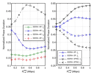
Figure 4.3: Normalized phase durations (tτ) versus UE’s required data rate
(RU Ereq) for EERA-4P scheme (left plot), EERA-2P and EERA-2PNC schemes (right plot) under RD/U = 1, Nc= 1, and w = 1.
Fig. 4.3 shows the phase durations (tτ) versus UE’s required data rate
(RU Ereq) under RD/U = 1, Nc = 1, and w = 1, where the phase durations
are normalized by the time duration of a frame. The left plot illustrates the EERA-4P scheme for phase duration from t1 to t4, and the right plot shows
the EERA-2P and EERA-2PNC schemes for durations t1 and t2. It can be
observed from the left plot of Fig. 4.3 that the third phase duration t3 will
first increase and decrease afterwards as RreqU E is enlarged. The reason is that
t3 of EERA-4P scheme is allocated with the links UE→RS and UE→BS,
which are considered the the transmission bottleneck in the relay-based net-work. Additional length of transmission time interval will be required for the UEs to satisfy its required data rate based on their power constraints. As the value of RreqU E is further increased, both the BS and RSs will also request for additional time intervals in order to fulfill their requirements on transmission
power and data rates. Therefore, the phase durations of t1, t2, and t4 will be
augmented after RreqU E = 0.6 Mbps, which results in decrease time duration of t3. Moreover, the first and fourth phase durations are comparably shorter
than that of the second and third phases under different RreqU E values. The reason is due to better link quality between BS and RSs that the links that in-volve UEs, which makes the EERA-4P scheme to allocate less time durations for t1 and t4. Furthermore, as show in the right plot of Fig. 4.3, the phase
duration t1 is increased in both the EERA-2P and EERA-2PNC schemes
as RreqU E is enlarged. Similar to the reason as explained for the EERA-4P scheme, the main reason is due to the major transmission bottleneck of the links UE→RS in t1 which consequently increases the duration of t1 to satisfy
the QoS requirements.
4.2
Performance Comparison
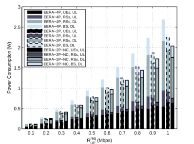
Fig. 4.4 illustrates the power consumption of the proposed 4P, EERA-2P, and EERA-2PNC schemes versus the UE’s required data rate RreqU E with
RD/U = 1, Nc = 1, and w = 1. In each scheme, the power consumption in
three different links are compared including the UL of UEs, the UL of RSs, the DL of RSs, and the DL of BS. It can be observed that the proposed EERA-2PNC scheme can provide the least total energy consumption com-pared to the EERA-2P and EERA-4P schemes under different RreqU E values. Furthermore, the total power consumption of the two DL transmissions, i.e., DL of RSs and BS, will be higher than that of the UL transmissions, i.e., the UL of RSs and UEs. Since both DL and UL share the same required data rate RD/U = 1 and channel condition, more energy consumption in DL
corresponds to less time required for DL’s phase durations. This can also be verified by observing from the EERA-4P scheme in the left plot of Fig.
0.1 0.2 0.3 0.4 0.5 0.6 0.7 0.8 0.9 1 0 0.5 1 1.5 2 2.5 3 RreqUE (Mbps) Power Consumption (W) EERA−4P, UEs, UL EERA−4P, RSs, UL EERA−4P, RSs, DL EERA−4P, BS, DL EERA−2P, UEs, UL EERA−2P, RSs, UL EERA−2P, RSs, DL EERA−2P, BS, DL EERA−2P−NC, UEs, UL EERA−2P−NC, RSs, UL EERA−2P−NC, RSs, DL EERA−2P−NC, BS, DL
Figure 4.4: Performance comparison for power consumption of the proposed EERA-4P, EERA-2P, and EERA-2PNC schemes versus the UE’s required data rate RreqU E with RD/U = 1, Nc = 1, and w = 1.
4.3 that the DL phase durations. i.e., the sum of t1 and t2, is larger than
the UL durations, i.e., the sum of t3 and t4. On the other hand, it can
be observe that the UL of RSs consumes comparably less energy than the other three cases of EERA-2PNC scheme. In the EERA-2PNC scheme, the power consumption of the network coded link LDU
r,u is categorized into UL if
the channel condition of RS→BS link is worse than the RS→UE link, i.e.,
gn
r,0 < gr,un ; while it is categorized into DL if gnr,0 ≥ gr,un . This reveals the
con-cept that the energy consumption of the network coded DU link is defined to belong to the link that consumes more energy, i.e., the link with worse channel condition. Since the channel condition gn
r,0 is in general better than
gn
r,u, most of the DU transmission of the EERA-2PNC scheme is conducted
in the DL of RSs in stead of the UL of RSs. Therefore, as shown in Fig. 4.4, less energy consumption is observed in the UL of RSs for the EERA-2PNC
0.2 0.4 0.6 0.8 1 0 0.5 1 1.5 2 2.5 3 3.5 RreqUE (Mbps)
Total Power Consumption (W)
0.2 0.4 0.6 0.8 1 0 0.05 0.1 0.15 0.2 0.25 0.3 0.35 0.4 0.45 RreqUE (Mbps) Outage Probability of UE EERA−4P EERA−2P EERA−2PNC QARA
Figure 4.5: Performance comparison between QARA method and proposed EERA schemes: power consumption (left plot) and outage probability of UE (right plot) versus UE’s required data rate RreqU E under RD/U = 1, Nc = 1,
and w = 1.
scheme under different RreqU E values.
Fig. 4.5 shows the power consumption and the UE’s outage probability of proposed EERA schemes compared to the QARA scheme under differ-ent required data rate RreqU E for each UE, where RD/U = 1, Nc = 1, and
w = 1. Note that the the total power consumption in the left plot of Fig.
4.5 includes the power consumption for all the network components, i.e., BS, RSs, and UEs. As the value of RreqU E is increased, the improvement of proposed EERA schemes becomes more significant in both power consump-tion and outage probability compared to the QARA scheme. As shown in the right plot of Fig. 4.5, it can be observed that the proposed EERA-4P, EERA-2P, and EERA-2PNC schemes can reduce the outage probability noticeably due to the adjustable phase duration. The main reason is that the extended transmission time can decrease the transmission power which
1 2 4 8 16 0 0.5 1 1.5 2 2.5 3 3.5 N c
Total Power Consumption (W)
1 2 4 8 16 0 0.1 0.2 0.3 0.4 0.5 N c Outage Probability of UE EERA−4P EERA−2P EERA−2PNC QARA
Figure 4.6: Performance comparison between QARA method and proposed EERA schemes: power consumption (left plot) and outage probability of UE (right plot) versus number of subcarriers per subchannel Nc under RreqU E = 1
Mbps, RD/U = 1, and w = 1.
assists in achieving the required power constraint. The outage probability of UEs can consequently be decreased, e.g., the EERA-4P scheme provides around 30% decrease in UE’s outage probability compared to the QARA method. Moreover, the two-phase bidirectional relaying schemes, i.e., the EERA-2P and EERA-2PNC algorithms, can share the same time resource for UL and DL transmissions in order to achieve higher multiuser diversity compared with the four-phase EERA-4P scheme, which results in lowered power consumption and outage probability of UEs.
Fig. 4.6 illustrates the total power consumption and UE’s outage proba-bility of the QARA and proposed EERA schemes under different number of subcarriers per subchannel Nc with RreqU E = 1 Mbps, RD/U = 1, and w = 1.
The proposed EERA-2PNC scheme outperforms the other three algorithms under different values of Nc. It is intuitive to observe that both the power
1 5 10 15 20 25 0 0.5 1 1.5 2 2.5 3 3.5 4 w Power Consumption (W) 1 5 10 15 20 25 0 0.05 0.1 0.15 0.2 0.25 0.3 0.35 0.4 0.45 0.5 w Outage Probability of UE EERA−4P, UEs EERA−2P, UEs EERA−2PNC, UEs QARA, UEs EERA−4P, All EERA−2P, All EERA−2PNC, All QARA, All EERA−4P EERA−2P EERA−2PNC QARA
Figure 4.7: Performance comparison between QARA method and proposed EERA schemes: power consumption (left plot) and outage probability of UE (right plot) versus weighting factor w under RU Ereq = 1 Mbps, RD/U = 1, and
Nc = 1.
consumption and outage probability are increased in all the schemes as the value of Nc is augmented since there are less number of allocatable resource
block in the network. Moreover, compared to the EERA-4P scheme, the increasing rate of outage probability versus Nc value is larger by adopting
the EERA-2P scheme attributing to further less number of resource block in the two-phase bidirectional relaying scheme. As shown in the right plot of Fig. 4.6, this performance degradation can be alleviated by adopting the proposed EERA-2PNC scheme with the assistance of network coding which effectively reduces the amount of data transmission by delivering combined packets. Fig. 4.7 shows the performance comparison for the proposed EERA schemes and the QARA algorithm under different weighting factors w of UEs with RU Ereq = 1 Mbps, RD/U = 1, and Nc = 1. Note that the power
consump-tion of UEs by adopting these four schemes are also presented in the left plot of Fig. 4.7 for comparison purpose. As the value of w is increased, the power
1 2 3 4 5 6 0 1 2 3 4 5 6 7 8 9 R D/U
Total Power Consumption (W)
1 2 3 4 5 6 0 0.05 0.1 0.15 0.2 0.25 0.3 0.35 0.4 0.45 R D/U Outage Probability of UE EERA−4P EERA−2P EERA−2PNC QARA
Figure 4.8: Performance comparison between QARA method and proposed EERA schemes: power consumption (left plot) and outage probability of UE (right plot) versus DL-to-UL ratio of UE’s required data rate RD/U under
RreqU E = 1 Mbps, Nc= 1, and w = 1.
consumption of UEs will remain at the same level for all the four schemes, i.e., around 0.5 Watt, which illustrates the minimum power consumption to achieve the target data rate. Both the RSs and the BS will consume more energy in order to reduce the UE’s outage probability as shown in the right plot of Fig. 4.7. Nevertheless, additional increase in weighting factor w cannot decrease the UE’s outage probability but to significantly augment the power consumption of both the RSs and the BS. For the QARA scheme, even though the increasing rate of the total power consumption is slower than that of the EERA schemes, excessive value of outage probability is obtained under different values of w.
Fig. 4.8 illustrates the performance comparison of power consumption and UE’s outage performance of the proposed EERA schemes and QARA al-gorithm under different DL-to-UL required data rate ratio RD/U with RreqU E =
1 Mbps, Nc = 1, and w = 1. The proposed EERA schemes can adjust the
phase duration which depends on the tradeoff between the power consump-tion and the outage probability. Therefore, consistent performance can be acquired by the EERA schemes compared to the QARA scheme when RD/U
changes. With the adopting of two-phase relaying technique, both the EERA-2P and EERA-EERA-2PNC schemes can provide better performance compared to the EERA-4P and QRAR algorithms since multiuser diversity is achieved by allowing more communication links to be chosen within a phase duration. It is also notice in both plots of Fig. 4.8 that the performance of EERA-2P and EERA-2PNC scheme becomes similar as RD/U is augmented. The reason is
that the network coding technique will become ineffective if the traffic load is extremely asymmetrical between DL and UL since there will not have suf-ficient data to be combined from one of the links. As a result, the merits of proposed EERA-2PNC scheme can be observed by outperforming the other algorithms under different network scenarios.
Chapter 5
Conclusion
In this thesis, the energy-efficient resource allocation (EERA) schemes are proposed for subchannel assignment, allocation of transmission power and phase duration in the relay-enhanced bidirectional orthogonal frequency-division multiple access (OFDMA) networks. Since the relay station (RS) can provide an additional two-hop signal path from the base station (BS) to the user equipments (UEs), each subchannel are partitioned into multiple phases in order to allocate different transmission links among the BS, RSs, and the UEs. Different influential factors are considered in the optimization problem, including subchannel assignment, power allocation, phase duration, QoS constraints, and direct/indirect transmission links. The EERA schemes are proposed based on four-phase and two-phase bidirectional relaying asso-ciated with network coding technique. It is shown in the simulation results that the proposed EERA schemes can provide higher network performance in energy conservation and outage probability with the ability to satisfy the corresponding QoS requirements.