21 Gb/s after 100 km OFDM long-reach PON
transmission using a cost-effective
electro-absorption modulator
Dar-Zu Hsu,1,2 Chia-Chien Wei,3,* Hsing-Yu Chen,2 Jyehong Chen,1 Maria C. Yuang,4 Shih-Hsuan Lin,4 and Wei-Yuan Li1
1Department of Photonics, National Chiao Tung University, Hsinchu 300, Taiwan
2Information and Communications Research Labs, Industrial Technology Research Institute, Hsinchu 300, Taiwan 3Department of Applied Materials and Optoelectronic Engineering, National Chi Nan University, Nantou 545, Taiwan
4Department of Computer Science and Information Engineering, National Chiao Tung University, Hsinchu 300,
Taiwan
Abstract: We experimentally demonstrate a superior performance of 2.1-Tb/s·km OFDM signal transmission over 100-km long-reach PONs. While the bandwidth of a 100-km SMF transmission system is limited to 4.3 GHz due to positive chirp, we successfully achieve spectrally-efficient 21-Gb/s signaling by using a cost-effective and low-chirp EAM, and adopting the 128-QAM format and adaptive subcarrier pre-emphasis.
©2010 Optical Society of America
OCIS codes: (060.3510) Lasers, fiber; (060.4080) Modulation; (060.4510) Optical communications.
References and links
1. T. Koonen, “Fiber to the Home/Fiber to the Premises: What, Where, and When?” Proc. IEEE 94(5), 911–934 (2006).
2. J. George, “Designing passive optical networks for cost effective triple play support,” in Proc. FTTH conference, Orlando, Florida, 4–6 (2004).
3. K. S. Kim, “On the evolution of PON-based FTTH solutions,” Inf. Sci. 149(1-3), 21–30 (2003).
4. P. D. Townsend, G. Talli, C. W. Chow, E. M. MacHale, C. Antony, R. Davey, T. De Ridder, X. Z. Qiu, P. Ossieur, H. G. Krimmel, D. W. Smith, I. Lealman, A. Poustie, S. Randel, and H. Rohde, “Long Reach Passive Optical Networks,” invited paper ThW1, IEEE LEOS Annual Meeting, Orlando, U.S.A. (2007).
5. R. Lin, Next Generation PON in Emerging Networks,” paper OWH1, Optical Fiber Communication Conference (OFC), San Diego, California (2008)
6. T. Pfeiffer, “Converged heterogeneous optical metro-access networks,” paper Tu.5.B.1, 36th European Conference and Exhibition on Optical Communication, Torino, Italy (2010).
7. R. S. Vodhanel, A. F. Elrefaie, M. Z. Iqbal, R. E. Wagner, J. L. Gimlett, and S. Tsuji, “Performance of directly modulated DFB lasers in 10-Gb/s ASK, FSK, and DPSK lightwave systems,” J. Lightwave Technol. 8(9), 1379–1386 (1990).
8. J. Armstrong, “OFDM for Optical Communications,” J. Lightwave Technol. 27(3), 189–204 (2009). 9. L. A. Neto, A. Gharba, P. Chanclou, N. Genay, B. Charbonnier, M. Ouzzif, C. Aupetit-Berthelemot, and J. L.
Masson, “High bit rate burst mode optical OFDM for next generation passive optical networks,” paper Tu.3.B.5, 36th European Conference and Exhibition on Optical Communication, Torino, Italy (2010).
10. U. Gliese, S. Norskov, and T. N. Nielsen, “Chromatic dispersion in fiber-optic microwave and millimeter-wave links,” IEEE Trans. Microw. Theory Tech. 44(10), 1716–1724 (1996).
11. W.-R. Peng, X. Wu, V. R. Arbab, K.-M. Feng, B. Shamee, L. C. Christen, J.-Y. Yang, A. E. Willner, and S. Chi, “Theoretical and Experimental Investigations of Direct-Detected RF-Tone-Assisted Optical OFDM Systems,” J. Lightwave Technol. 27(10), 1332–1339 (2009).
12. J. Wang, and K. Petermann, “Small signal analysis for dispersive optical fiber communication systems,” J. Lightwave Technol. 10(1), 96–100 (1992).
13. C.-C. Wei, “Small Signal Analysis of OOFDM Signals Transmission with Directly Modulated Laser and Direct Detection,” Opt. Lett. (to be published).
14. F. Devaux, Y. Sorel, and J. F. Kerdiles, “Simple measurement of fiber dispersion and of chirp parameter of intensity modulated light emitter,” J. Lightwave Technol. 11(12), 1937–1940 (1993).
15. Y.-M. Lin, P.-L. Tien, M. C. Yuang, S. S. W. Lee, J. Chen, S.-Y. Chen, Y.-M. Huang, J.-L. Shih, and C.-H. Hsu, “A novel passive optical network architecture supporting seamless integration of RoF and OFDMA signals,” IEEE Photon. Technol. Lett. 22(6), 419–421 (2010).
#138046 - $15.00 USD Received 11 Nov 2010; revised 9 Dec 2010; accepted 10 Dec 2010; published 16 Dec 2010
16. ITU-T Recommendation G.975.1, Appendix I.9 (2004). 1. Introduction
Passive optical network (PON) technology has been considered to be one of the most promising candidates for cost-efficiently providing high bandwidth to end-users [1–3]. With the uses of passive components between the central office and end-users, the PON solution boasts low cost, high reliability, and easy maintenance. Meanwhile, the demands for higher capacity and quality of service (QoS) are ever increasing and electronic interfaces have still been the main bottlenecks within optical network systems; a new type of optically amplified large-split long-reach PON has recently received a lot of attention [4–6]. The long-reach PON (with a reach being up to 100 km) can be integrated with existing networks, such as optical metro core networks and traditional PONs, resulting in drastic reduction in the number of electronic interfaces and hence capital and operational cost.
To further increase the economy of long-reach PON systems, researchers consider the use cost-effective transmitters, such as directly modulated DFB laser (DML) and electro- absorption modulated laser (EML). Nevertheless, for transmitting signals at the data rate of 10 Gb/s and beyond based on the traditional binary modulation format (e.g., on-off keying), these cost-effective transmitters give rise to fiber dispersion and intrinsic chirp problems which severely limit the maximum transmission distance to much less than 100 km [7]. Thanks to the advance in digital-signal-processing (DSP) technology, orthogonal frequency-division multiplexing (OFDM)-PON has been envisioned as a prominent modulation/multiplexing technique. On the basis of using higher order quadrature amplitude modulation (QAM) format [8,9], OFDM-PON effectively achieves high spectral efficiency and ultimately lowers the bandwidth requirement of components. However, through DMLs or EMLs, an optical OFDM signal is generated in the form of double-side band (DSB), and unavoidably, the optical signal is frequency-chirped. As a result, the bandwidth of an OFDM transmission system is limited by dispersion- and chirp-related power fading, especially under a long transmission distance of 100 km as is the case for long-reach PONs.
In this work, we experimentally demonstrate optical DSB-OFDM transmission over 100-km single-mode fiber (SMF) link using a cost-effective 10-GHz bandwidth electro-absorption modulator (EAM). Because the bandwidth of an SMF transmission system is curtailed due to positive chirp, the bias voltage of the EAM is adjusted to balance the trade-off between the chirp parameter and the transferring linearity of the EAM. Moreover, the power of each OFDM subcarrier is also adaptively pre-emphasized to optimize the transmission performance. As such, we successfully achieve a superior performance of 2.1 Tb/s·km (21 Gbps100 km) through economical uses of EAM, direct-detection, and the 128-QAM modulation format.
2. Bandwidth of transmission systems
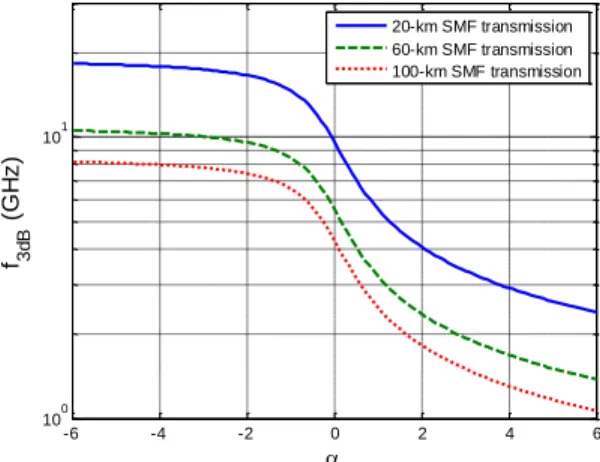
As an optical OFDM signal is generated in the form of DSB, an electrical OFDM subcarrier is translated into two conjugated optical subcarriers on both sides of an optical carrier [10]. At the end of fiber-link transmissions, unfortunately, residual dispersion will destroy the conjugated property of the optical subcarriers with respect to the optical carrier, resulting in a well-known power fading. Without considering fiber loss, the received power of an OFDM subcarrier is proportional to cos (22 2 2Lf2) [10], where 2 is the group velocity dispersion (GVD) parameter, L is the fiber length, and f is the frequency of an electrical OFDM subcarrier. Accordingly, the 3-dB bandwidth of a transmission system is f3dB 1 | 82L|, and the corresponding bandwidth-distance product is f3dBL L | 82|. According to the formula of 3-dB bandwidth, a long-reach OFDM-PON over a 100-km standard SMF ( 2 21.66
ps2/km) exhibits the 3-dB bandwidth of only about 4.3 GHz. Hence, to fully utilize the limited
#138046 - $15.00 USD Received 11 Nov 2010; revised 9 Dec 2010; accepted 10 Dec 2010; published 16 Dec 2010
bandwidth, OFDM signals should be encoded at baseband without a bandwidth-wasting guard band [11]. Nevertheless, if an OFDM signal is chirped, the power loss owing to power fading at the end of transmissions can be given as (12) cos (22 2 2Lf2tan1) [12,13], where is the chirp parameter. Note that positive chirp reduces the bandwidth of an OFDM transmission system over standard SMF. As a result, the 3-dB bandwidth of a transmission system can be given as,
1 1 2 2 3dB 2 2 tan tan 1 2 . 2 f L (1)
While of a commercial DFB laser is generally larger than 6, the corresponding bandwidth after 100-km SMF, as shown in Fig. 1, is less than about 1.1 GHz. This fact implies that a very high order QAM format must be employed to transmit signals at the data rate of 10 Gbps or beyond. Hence, an EML (or EAM) with
1 is more suitable for a cost-efficient long-reach OFDM-PON. -6 -4 -2 0 2 4 6 100 101 f 3d B ( G H z ) 20-km SMF transmission 60-km SMF transmission 100-km SMF transmissionFig. 1. 3-dB bandwidth of SMF transmission system as a function of the chirp parameter.
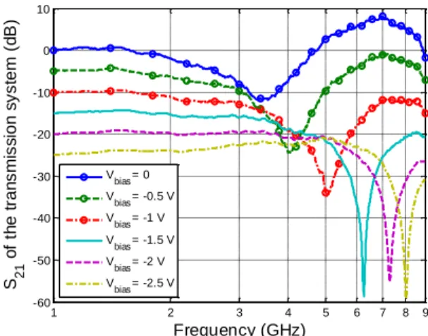
Via a network analyzer, we display in Fig. 2 the measured frequency responses of an EAM-based transmission system over 100-km SMF under different bias voltages. Notably, the first null point of the frequency response, fnull, can be used to estimate the bias-dependent chirp parameter through the equality [14]:
2 2 2 null tan 2 2 Lf (2)
From Fig. 2, we observe the system bandwidth strongly depends on the bias voltage, and the bandwidth can be even larger than that of a chirp-free system of which fnull is about 6.1 GHz, when bias voltage is smaller than ~1.5 V. Since the bandwidth is not the only concern to the signal performance, in the following section, we present our EAM-based OFDM transmission system to evaluate the transmission performance.
#138046 - $15.00 USD Received 11 Nov 2010; revised 9 Dec 2010; accepted 10 Dec 2010; published 16 Dec 2010
1 2 3 4 5 6 7 8 9 -60 -50 -40 -30 -20 -10 0 10 Frequency (GHz) S 21 o f th e t ra n s m is s io n s y s te m ( d B ) Vbias= 0 V bias= -0.5 V V bias= -1 V V bias= -1.5 V V bias= -2 V Vbias= -2.5 V
Fig. 2. Measured frequency responses of an EAM-based signal after 100-km SMF. 3. Experimental results AWG Scope SMF 50 km EAM Vbias Bias T LD Att. SMF 50 km O/E EDFA electrical optical
Fig. 3. Experimental setup of the OFDM transmission system.
The experimental setup for an OFDM transmission system over 100-km standard SMF is shown in Fig. 3. Although a power splitter or multiple circulators need to be placed in a remote note of a practical PON system [15], we adopt a point-to-point transmission to emulate a long-reach OFDM-PON, since the loss of the remote note in PONs can be compensated by an optical amplifier. The baseband electrical OFDM signal is generated by a Tektronix® AWG7102 arbitrary waveform generator (AWG) using the Matlab® program. The signal processing of the OFDM transmitter consists of serial-to-parallel conversion, QAM symbol encoding, inverse fast Fourier transform (IFFT), cyclic prefix (CP) insertion, and digital-to-analog conversion (DAC). The sampling rate and DAC resolution of the AWG are set to be 12 GSample/s and 8 bits, respectively, and CP of 1/16 is used. The OFDM signal contains 128 subcarriers of 128-QAM format to occupy 3-GHz bandwidth with a fast-Fourier transform (FFT) size of 512, yielding ~23-MHz subcarrier spacing and a total data rate of 21 Gbps. An EAM is used to generate an optical DSB OFDM signal without a guard band. The launch power is 1 dBm, and an EDFA with 23-dB gain is inserted in the middle of transmission span. After transmission in SMF and direct-detection via a PIN, the received electrical signal is captured by a Tektronix® DPO 71254 with the 50-GSample/s sampling rate, 8-bits analog-to-digital conversion resolution, and the 3-dB bandwidth of 12.5 GHz. The off-line DSP program is used to demodulate the vector signal, and the demodulation process includes synchronization, FFT, one-tap equalization, and QAM symbol decoding. Lastly, the bit error rate (BER) performance is calculated from the measured signal-to-noise ratio (SNR).
#138046 - $15.00 USD Received 11 Nov 2010; revised 9 Dec 2010; accepted 10 Dec 2010; published 16 Dec 2010
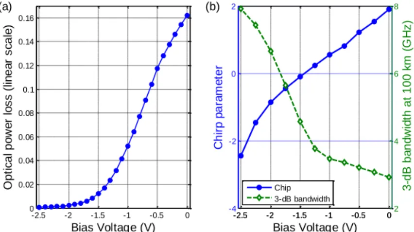
-2.5 -2 -1.5 -1 -0.5 0 -4 -2 0 2 Bias Voltage (V) C h ir p p a ra m e te r (b) -2.5 -2 -1.5 -1 -0.5 02 4 6 8 3 -d B b a n d w id th a t 1 0 0 k m ( G H z ) Chip 3-dB bandwidth -2.5 -2 -1.5 -1 -0.5 0 0 0.02 0.04 0.06 0.08 0.1 0.12 0.14 0.16 Bias Voltage (V) O p ti c a l p o w e r lo s s ( lin e a r s c a le ) (a)
Fig. 4. (a) Optical power loss and (b) chirp parameter and 3-dB bandwidth at 100-km SMF of the EAM as functions of bias voltage.
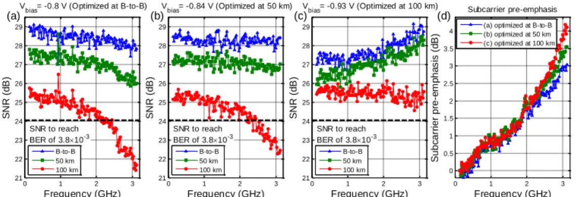
In Figs. 4(a) and (b), we display the amplitude and phase characteristics of the EAM, respectively, and the linear electrical-to-optical (E/O) conversion region is between 1.1 V and 0.5 V. Within this region, the measured chirp parameter ranges from 0.3 to 1.2, and the corresponding transmission bandwidth at 100-km SMF is from 3.5 GHz to 2.4 GHz. Accordingly, the transmission bandwidth at 100-km SMF could be a critical issue for our 3-GSymbol/s signal, when the electrical signal is operated in this linear E/O conversion region. Furthermore, to evaluate the signal performance, Figs. 5(a)-(c) depict the measured SNR of every OFDM subcarrier with and without transmissions, and we use the different profiles of subcarrier power pre-emphasis which are illustrated in Fig. 5(d). While both the bias voltage and the subcarrier pre-emphasis are optimized at back-to-back, the operational bias voltage is
0.8
V, which is about the center of the linear E/O conversion region. However, as shown in Fig. 5(a), after 100-km SMF transmission, the subcarriers at high frequency suffer severe SNR penalty and fail to achieve the FEC threshold (BER3.8 10 3 and redundancy ratio of 7%) [16]. This implies a trade-off problem between bandwidth and E/O conversion linearity. For example, a bias voltage of 0.8 V yields wider transmission bandwidth, however, at the expense of lower conversion linearity. Therefore, the bias voltage should be slightly reduced to obtain wider bandwidth and better transmission performance after SMF transmission. In Fig. 5(b), subcarrier power pre-emphasis is optimized according to the SNR at 50-km SMF, and the bias voltage is slightly down shifted to 0.84 V. Furthermore, by optimizing the subcarrier power pre-emphasis at 100 km and reducing the bias voltage to 0.93 V, we show the measured SNR in Fig. 5(c) which demonstrates that the subcarriers at high frequency suffer less SNR penalty compared to that in Fig. 5(a), and all the subcarriers achieve the FEC threshold within 100-km transmission. Moreover, we plot in Fig. 6 the BER performance of the EAM-based OFDM signal, with the corresponding constellations shown in the insets of the figure. Each BER curve is adaptively optimized at a specific transmission distance, and the transmission penalty over 100-km at the FEC threshold is as low as ~1 dB.
#138046 - $15.00 USD Received 11 Nov 2010; revised 9 Dec 2010; accepted 10 Dec 2010; published 16 Dec 2010
0 1 2 3 21 22 23 24 25 26 27 28 29 Frequency (GHz) S N R ( d B ) V
bias= -0.8 V (Optimized at B-to-B) (a) SNR to reach BER of 3.810-3 B-to-B 50 km 100 km 0 1 2 3 21 22 23 24 25 26 27 28 29 Frequency (GHz) S N R ( d B ) V bias= -0.84 V (Optimized at 50 km) (b) SNR to reach BER of 3.810-3 B-to-B 50 km 100 km 0 1 2 3 21 22 23 24 25 26 27 28 29 SNR to reach BER of 3.810-3 Frequency (GHz) S N R ( d B ) V bias= -0.93 V (Optimized at 100 km) (c) B-to-B 50 km 100 km 0 1 2 3 0 0.5 1 1.5 2 2.5 3 3.5 4 Frequency (GHz) S u b c a rr ie r p re -e m p h a s is ( d B ) (d) Subcarrier pre-emphasis (a) optimized at B-to-B (b) optimized at 50 km (c) optimized at 100 km
Fig. 5. SNR of each subcarrier with parameters optimized at (a) back-to-back, (b) 50 km, and (c) 100 km, and (d) the profiles of corresponding subcarrier pre-emphasis.
-12 -11 -10 -9 -8 -7 -6 -5 -4 10-5 10-4 10-3 10-2 Received power (dBm) B E R B-to-B (Vbias= -8.0 V) 50 km (V bias= -8.4 V) 100 km (V bias= -9.3 V)
Fig. 6. BER and constellations of OFDM signals (dash line denotes the FEC limit). 4. Conclusion
In this paper, we have experimentally demonstrated optical DSB-OFDM transmission over 100-km SMF link using a cost-effective 10-GHz bandwidth EAM and direct-detection. Although the bandwidth of 100-km EAM transmission system is limited to less than 4 GHz due to the positive chirp, we have efficiently used 3-GSymbol/s 128-QAM OFDM signaling in combination with optimized bias voltage and subcarrier power pre-emphasis to achieve a superior performance of 2.1 Tb/s·km over 100-km SMF.
Acknowledgment
The authors would like to thank the National Science Council, Republic of China, Taiwan for financially supporting this research under Contract No. NSC 99-2218-E-260-003- and NSC 99-2221-E-009 046 -MY3.
#138046 - $15.00 USD Received 11 Nov 2010; revised 9 Dec 2010; accepted 10 Dec 2010; published 16 Dec 2010