18th Annual International Conference of the IEEE Engineering in Medicine and Biology Society, Amsterdam 1996 1.2.3: Bioelectrodes I
A
front-end biopotential measurement module
Chun-Yu Chen
,
Yue-Der Lin
, Fok-Ching Chong
and
*Shing-Ming Sung
Department
of Electrical
Engineering,
National Taiwan
University
*Department of Neurology, Taipei Municipal
Jen-Ai
Hospital
ABSTRACT
A front-end biopotential measurement
module which c:ould be applied to the measurement of surface biopotential is
presented in this study. This module,mainly composed of an isolation amplifier (iso. amp) and an active electrode,has the advantages of
low cost, easy implementation and no need of skin preparation arid paste. The user could also easily m w this module to their specific applications. The #design of the measurement module and its characteristics are ais0 demonstrated.
Keywords : biopol.ential , isolation amplifier (is0 amp) , active electrode
INTRODUCTION :
In clinical diagnosis, the recording of surface biopotential is important.The usual method of measuring surface biopotential is the gluing of nonpolarizable Ag/AgCl electrodes to the desired positionu. This would waste time as
the techcians should prepare the surface of shn,degrease the recording area by cleaning it with alcohol, then apply the conducting paste to Ag/AgCl electrodes with collodion or hold them in place with rubber straps. These skin preparations could cause further drawbacks such as a)irritation of the patient's skin and b)potential shift or signal-transmit error due to long time measurementc) environmental noise is easily induced by the lead wire that links the electrode and the amplifier[ 11. For safety sake, galvanic isolation of the patient during bioelectric measurement is necessary. An is0 amp is usually needed to meet this requirement, yet the price of a commercial product(ex:
AD210) is expensive and this economical problem would be enhanced in multichannel recording,such as electroencephalogram(EEG).
The goals of this study is to overcome the drawbacks described above. The active electrode using an FET-input op amp instead of the AglAgC1 ebectrode. NO more skin preparations are required and the conductive
0-7803-381 1-1/97/$10.00 OIEEE
paste becomes unnecessary as the input impedance of the active electrode is high
enough compared with the skin impedance, and the noise induced by the lead wire would be reduced as the output impedance of the active electrode is very low. The active electrodes were connected to the designed iso.
amp, thus the biopotential measurement module was constructed. The user could only add post-stage amplifiers and filters to this module to fit their specific surface biopotential application. This low-cost front-end measure- ment module is helpful especially in the laboratory as the design of measurement system is desired.
METHODS AND MMEFUALS :
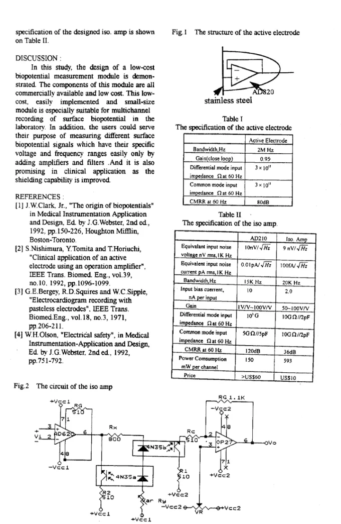
The structure and the electric circuit of the active electrode are demonstrated in Fig. 1,
which looks somewhat like the work of
Nishimura er a1.,[2]. In order to have a very high input impedance and small size, an FET- input op amp (AD820, Analog Devices, less than four US dollars) in surface mount package that connected as a voltage follower was adopted. The electrode material is stamless steel as its slun-to-electrode impedance is relatively less affected by the presence of perspiration[3].
The circuit of the isolated amplifier is shown in Fig.2. The overall gain of the iso. amp is 50. The users could add post-stage amplifiers and filters according to the bioelectric event being concerned. The is0 amp
is composed of instrumentation amplifier, optoisolators, low-noise op amp and resistors. One feature of this is0 amp is the adding of a
matched optoisolator on the source side, the idea is drawn from the design criterion of Burr Brown IS0100 is0 amp[4], to improve the linearity between LED input current and output collector current.
RESULT
:The features of the active electrode is
listed on Table I. The requirements for the electrode of very high input impedance and very low output impedance are fulfilled. The
18th Annual International Conference of the IEEE Engineering in Medicine and Biology Society, Amsterdam 1996 1.2.3: Bioelectrodes I
Bandwidth,Hz Gain(close loop) Differential mode input inipedance R a t 60 Hz Common mode input impedance Q a t 60 Hz
CMRR at 60 Hz specification of the designed iso. amp is shown
on Table 11. Active Electrode 2M Hz 0 95 3 x 10" 3 x IO" 80dB DISCUSSION :
In t h ~ s study, the design of a low-cost biopotential measurement module is demon-
strated. The components of this module are all commercially available and low cost. This low-
cost, easily implemented and small-size
module is especially suitable for multichannel recording of surface biopotential in the laboratory. In addition. the users could serve their purpose of measuring Werent surface biopotential signals which have their specific voltage and frequency ranges easily only by
addmg amplfiers and filters .And it is also promising in clinical application
as
the shielding capability is improvedEquivalani input noise
REFERENCES :
[ 11 J.W.Clark, Jr., "The origin of biopotentials"
AD210
1
Is0 Amp IOnV/JFi;I
9 n v / min Medical Instnunentation Application and Design. E d by J.G.Webster, 2nd ed.,
1992. pp. 150-226, Houghton Mifnin,
Boston-Toronto.
S.Nishimura, YTomita and T.Horiuchi, "Clinical application of
an
active electrode using an operation amplifier",IEEE
Trans. Biomed Eng., vo1.39,no.10. 1992, pp. 1096-1099. "Electrocardiogram recording with pasteless electrodes".
IEEE
Trans. Biomea.Eng., vo1.18, n0.3, 1971, G.E.Bergey, R.D. Squires and W.C.Sipple,Pp. 206-2 1 1.
voltage n V rms. I K HZ
I
[4] W.H.Olson, "Electric'al safety", in Med~cai
Instrumentation-Application and Design, Ed. by
J.C.
Webster. 2nd e d , 1992, pp.75 1-792.current pA ms, I K Ht Eandwidth,Hz Input bias cument,
nA per input Gain
Differential mode input impedance flat 60 Hz
Common mode input
Fig.2 The circuit of the is0 amp
15K Hz 20K Hz IO 2.0 I VN-IOOVN 50- 1 OOVN 1 OG R //2pF 5Gf2N5pF I O G ~ / / ~ D F 10'G +vcc 1
K
m
impedance R a t 60 fi C M R R a t 6 0 H z Power ComsumptionFig. 1 The structure of the active electrode
I2OdB 36dB IS0 593 stainless
steel
I
m W per channel Table IThe specification of the active electrode
RG 1 . 1 K