Efficient Algorithms and Architectures for MPEG-4
Object-Based Video Coding
Hao-Chieh Chang, Yi-Chu Wang, Mei-Yun Hsu, and Liang-Gee C h e n DSP/IC Design Lab, Department of Electrical Engineering
National Taiwan University, Taipei, Taiwan, R.O.C.
Abstract
This paper presents efficient algorithms and architectures for the MPEG-4 object- based video coding. The novel coding tools supporting for object-based coding will much increase the computational burden, in comparison with conventional frame- based video coding system. In order to process these extra computational tasks effectively, design techniques both on algorithms and architectures have to be addressed. By the careful examination of computational behavior of algorithms, the best-matched computation models can be derived, and the target architectures can be determined. Based on this design strategy, the computational behavior of the M P E G 4 video coding tools at simple/core profiles and level 2 is explored first. Then, by considering the analysis results, eficient algorithms and architectures are developed to meet the design specifications. The shape coding tool, which is the most computation-extensive task supporting for object-based functionality is selected as our study case. The real-time performance of shape coding can be easily achieved by the proposed architecture approximately running at 7.8 MHz while the optimized software running on a full-speed RISC (Ultra Sparc, 300Mhz) can only have about
1/10 performance.
I. Introduction
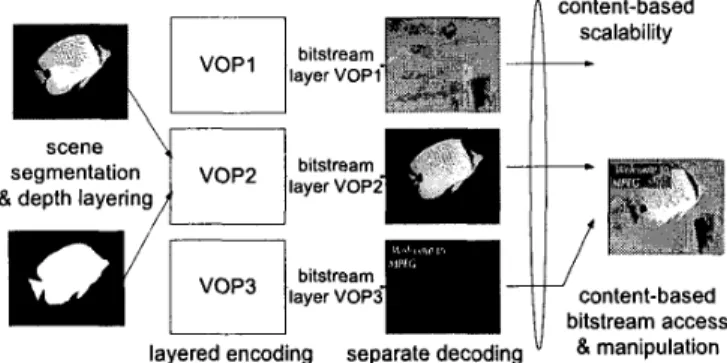
One of the most interesting features of MPEG-4 [ l ] is the object-based functionality, This functionality provides the powerful capability that end-users can direct access the video content (objects) rather than video frames at the video scenes in the multimedia terminal. Figure 1 shows a typical example. In such a visual communication system, one or more arbitrarily shaped regions in the video scenes are first segmented from the background to form active foreground objects. Then, these video objects can be processed, coded and transmitted. Since the video objects are coded separately, the capability of object-based processing can be easier to achieve. At the receiver side, bitstream is received from transmission channel and de-multiplexed into several elementary streams, which represent separate coded video objects. Video objects can be decoded from elementary streams and then display at the terminal.
Generally, many computation-intensive tasks, such as video segmentation and video coding are required to realize a real-time interactive visual communication system. Moreover, the object-based video coding demands extra processing tasks, including MB-based shape coding [2], VOP formation, and VOP padding based on the consideration of MB-based coding scheme. The heavy demand for computation power makes the software solutions more difficult to be feasible. In addition, many previous hardware designs of video codec did not report the
efficient solutions for the object-based video coding. This motivates the need for the efficient architecture design for object-based video coding to fit the real-time requirement of MPEG-4 video system. In this paper, we will highlight the design approach of shape coding tool due to its high computational complexity.
w'
rl
3'0" layer bitstream VOPlayered encoding separate decoding
I
content-based scalability-
content-based bitstream access & manipulationFigure 1. Object-based Visual Communication
The contribution of this paper is the optimizations for the shape coding tool of MPEG-4 video coding derived at both the algorithm and architecture levels. The optimized algorithms and architectures can be implemented in the real-time interactive video systems such that object-based processing can be finished efficiently. This paper is organized as follows. In Section 11, completely computational analyses for these algorithms are given first. Based on these analyses, we propose some efficient design concepts for real-time implementation of MPEG-4 Video codec. Section 111 illustrates the design case, that is, the shape coding architecture based on the design concepts presented in Section 11. Finally, we summary our discussion in Section IV.
11.
The Design Approach
In our design strategy, analysis for computational behavior is the essential step in the system design flow. Basically, the computational behaviors of object-based MPEG-4 video coding algorithms are carefully studied such that those algorithms can be effectively implemented with proper design techniques. Since a practical system usually involves various types of processes (algorithms), they should be optimized in different design techniques. Based on this design concept, our design approach is briefly summarized as follows. First, both simulative (run- time) and theoretical (statistic) analysis of computation complexity for MPEG-4 video codec are applied. This analysis would reveal the computational behavior of a practical MPEG-4 video coding system. Second, based on the knowledge of the computational behavior, efficient algorithms as well as several architectural techniques [3][4], such as data-reuse, bit-level processing, etc are developed. These techniques are proven to achieve a very good improvement for system performance.
A. Computational Complexity Analysis
MPEG-4 Simple Profile and Core Profile @ Level 2 (typically CIF, 60Hz,
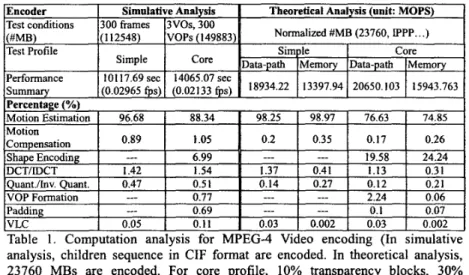
5 12Kbit/s-2Mbit/s) are selected as the test conditions. Then, two different approaches based on the RfSC-based computation model [ 5 ] are adopted to analyze the compiexity. In the theoretical analysis, computation cost and data transfer traffic can be caIculated while the simulative analysis provides the run- time information of a practical system (Ultra Sparc, 300MHz). The analysis results are briefly summarized in Table 1. The analysis results reveal that a pure software solution running on a RlSC without great optimization is impossible to perform the real-time encoding. Although several works report the software optimization for real-time MPEG-4 video decoding [6][7], very few works report good software implementation results for real-time MPEG-4 video encoding with object-based functionality and high specification.
Table 1. Computation anaIysis for MPEG-4 Video encoding (In simulative analysis, children sequence in CIF format are encoded. In theoretical analysis, 23760 MBs are encoded. For core profile, 10% transparency blocks, 30% boundary blocks and 60% opaque blocks are used for test.)
B. Efficient Design Concepts
The anaIysis results show that motion estimation tool, shape coding tool are the most critical computationai bottleneck. To effectively improve the system performance, design optimization shouId be applied on these two coding tools. First, we consider the optimization of motion estimation. In fact, many approaches (both software [6] and hardware [S)) have reported very good research results for the optimization of h l l search motion estimation. We can briefly conclude that systolic array processor is the best target architecture to realize full search motion estimation with wide search range and block size (high specification).
The second part needs to be optimized is the shape coding tool, which contributes the major computation load for object-based functionality. For example, to encode a binary alpha-plane sequence in CIF-format 30fps (with 30% boundary MB), computation power of 2 giga-operations per second (GOPS) are required. This requirement leads to a very heavy computation load on DSPs or
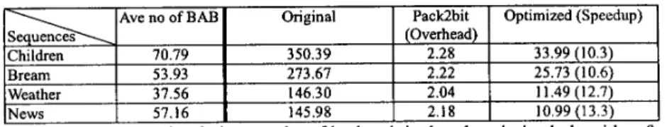
GPPs if a pure software implementation of shape coding is adopted. To optimize the shape coding tool, data-type parallelism technique plays a quite vital role. Since shape information of a video object plane is represented in binary format, several binary data can be concatenated and then processed simultaneously. In other words, if these bit-represented data are compacted into word-aligned format, the general word-aligned processor can gain much performance improvement from the bit-level parallelism. Table 2 illustrates the simulation results for shape coding with and without the data-type optimization. In this simulation, three sequences of 100 frames in CIF-format picture are tested.
1
Pack2bitI
Optimized(Speedup)I
INews I 57.16 I 145.98
binary motion estimation on a 300 MHz Ultra Sparc workstation. (unit: second) As shown in Table 2, although the 10-12 times of speedup can be achieved from the data-type optimization (i.e. binary data compaction), the computation requirement of binary motion estimation (BME) is still a very heavy load (up to 1GOPS) for the shape coding. On the other hand, the other tasks in the shape coding flow, such as CAE and uphub-sample, can not gain very much from the data-type optimization. Basically, these tasks are bit-serial processing types. In other word, the input data (pixelshits) have to be processed one-by-one, rather than parallel processing. Table 3 shows the more detailed analysis result for CAE- based shape coding including data-type optimizatiodnon-optimization. From the analysis results, we can conclude that the shape coding tool employs the major computation tasks: BME, CAE and uphub-sampling. Almost 99% computation load will be spent on these three tasks. Thus, to optimize the shape coding tool, these three tasks are the major targets to be optimized, especially for BME.
methods
Byte Representation Bit Representation
3759.02 92.2% 956.18 78.8%
202.21 5.0% 125.57 (10.4%)
U /sub-Sam le 74.36 1.8% 114.33 9.4%
Others 0.73 0.3% 16.65 1.8%
Total 1212.73 (100%
Table 3. Theoretical computation analyses for shape coding. (Units: MOPS)
111. Shape Coding Architecture
In this section, we will highlight some important design issues of the shape coding architecture, such as bit-level processing and data reuse. In addition, the design reuse concept is also derived in this section. The analysis results indicate that three major system components (BME, CAE and re-sampling units) have to be hardware-accelerated so as to achieve the maximum optimization. The
architecture designs of these components are discussed in the following subsections.
A. BME Architecture Design
Due to the data locality and parallel processing property, systolic array is the best target architecture for motion estimation block matching. Here, I-D array architecture [9] is adopted for BME.
As described previously, the binary pixels can be compacted and processed simultaneously. The MB width is selected as the word length of the compacted data. This makes the data processing follow the row-by row flow, which is easier to design. The
S A D
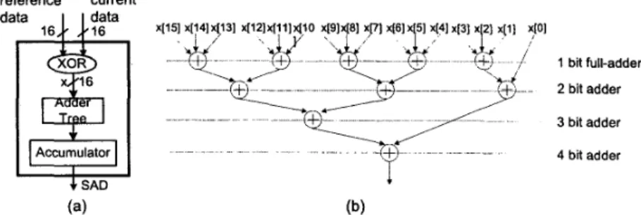
PE, as shown in Figure 2, is designed to calculate the partial SAD of one row every cycle. One row of current MB and one row of candidate MB are compared first by bit-wise XOR. Then the resulted row of binary data, which represent the difference values between pixels of these two rows, are summed up to get the partial SAD of one row by adder tree. The accumulator sums up 16 rows of partialS A D
to obtain the SAD of one candidate MBreference current data data 16 t6 Accumulator I .( SAD (a) (b)
Figure 2. (a) Architecture of SAD PE. (b) Adder tree structure
SRO SR1 current data 31 0 search range , 16
’
19 1I
[ 15:Ol1
PE15. . .
PE0 PE 1 comparitorFigure 3. Architecture of data dispatch based BME (DDBME)
Pixels of a row are stored in a storage entry. However, the desired data for candidate MB lie across two storage entries when the candidate position is not located at MB grid. This means extra operations (shift and pack) are required to obtain the desired reference data. Thus, the Data-Dispatched BME (DDBME, see Figure 3) architecture is proposed to avoid the extra shifting and packing operations. In the beginning, two top horizontally adjacent rows in search range
(SR0[3 1 :O]) are read from search range buffer. SR0[3 1 : 161 are dispatched to PEO, SR0[30: 151 are dispatched to PE1 and so on. In the next cycles, two horizontally adjacent rows in second line of search range (SR1[31:0]) are read out and dispatched to PE in the same way. After 16 cycles from the beginning, the SAD of 16 adjacent candidate MBs are obtained. They are stored in latches and sent to the comparitor one be one. The comparitor will choose the motion vector indicate to the MB with minimal SAD. At the same time, the PE array continuously calculates next 16 adjacent candidate MBs. Since the storage word length is 16, the number of PE must be multiple of 16 to completely process the read data.
The data flow and pixels packing affect the utilization of data reuse. In the case of row-by-row (horizontal) pixels packing and vertical processing flow, extra shift and pack operations are required to produce desired bits for PE. On the other hand, if the pixels’ packing is column by column, the vertical candidate MB processing flow does not require the extra shift and pack operations. We can conclude that the direction of candidate MB processing flow plays an important role in the design of BME. For processing flow that is in the same direction with pixels packing, maximum data reused ratio can be achieved. Using 16 PES to encode 100 CIF VOP with 30% boundary MB in average, the data transfer for “cross” data flow and packing direction is 56.81 Mbytels. For “identical” data flow and packing direction which is adopted in DDBME, only 14.6 Mbytels is required. It is 32x reduction compared with RISC.
Identical candidate MB processing flow and
pixels packing direction
Cycles(/s) 7.29M
Memory access(byte/s) 14.6M
Cross RISC
7.29M
1
926.99M 56.81MI
467.14M Table 4. Performance summary of different approachesB. Delay-line Model
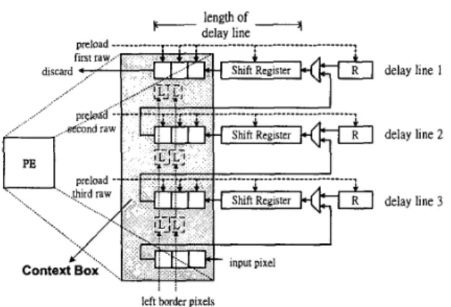
Many image processing have window-based operations. Context generation for both CAE and up-sampling in shape coding require such kinds of operations. In these operations, current pixel in process usually references several neighbor pixels in a pre-defined template. For pixel by pixel processing in raster scan order, most of the reference pixels of two adjacent processing are duplicate. This leads to the memory access redundancy if all referenced pixels for current pixel are reloaded every time. Actually, with a few registers in proper data-flow arrangement, data reuse can remove the redundant access. Figure 4 shows the general form of the delay-line model (DLM). Each current pixel of MB is loaded into DLM, and flows through the shift registers array in DLM. Registers in context box are arranged such that various contexts can be achieved. By employing this model, the required context can be achieved at every cycle.
For block-based processing, the neighboring pixels to be referenced may locate outside the current block. The region outside the current block is called the border region. The border region contains pixels from the previously processed blocks and the unknown pixels (not been processed yet). If unknown pixels are referenced, rightmost or lowest pixels of current block are used for reference. For handling these boundary cases, some registers excepts the shift registers array in
normal data flow are inserts into context box.
length of IC- delay line __ji
delay line I
delay line 2
delay line 3
left border pixels
Figure 4. Block diagram of the delay-line model.
At the beginning of processing each active block, upper border regions are pre- loaded into delay lines. Pixels in left border are referenced only for left boundary pixels of current block. No current pixel will refer them as being right position of template. Hence they are stored and flow through special path. Registers ‘R’ are added to store upper-and-right border pixels. Similarly, only pixels in upper-and- right part of current block have to refer upper-and-right border pixels. Therefore, after pixel in register R flow into delay line, this path to delay line is closed and another path from lower delay line is selected instead. In this way, the operation can smoothly process. In the subsection 111-C and 111-D, we explain how to reconfigure the delay-line model to implement CAE and up-sample unit.
C. CAE
CAE unit includes context generation and binary arithmetic coder. Many efficient designs of arithmetic coder have been proposed in [lO][l I]. The context generation can be implemented by employing the delay line model [3]. Some modification [4] are made to support CAE with different block sizes. The block size can be 16x16, 8x8 or 4x4 dependent on conversion ratio. In order to achieve a more cost-effective solution, different approach from [4] is adopted. We use multiplexes to change virtual length of delay line based on the fact: the delay line length is equal to block width. Thus, number of shift registers in one delay line is 16. Depending on the block size of current encoding block, the data in delay line3 may change its original data flow into delay line2 through muxl (4x4) or mux2 (8x8) or mux3 (16x16). The similar data flow selection can be also made for the flow from the delay line2 to delay line1
.
When the block size is 4x4, the value of register 2 will not be updated. Hence a special path from current pixel input to mux7 is selected. Registers outside the virtual length of delay line can be gated to save power. Registers in region I1 and 111 are gated for processing 4x4 block. Registers in region 111 are gated for processing 8x8 block.CD delay hne I (2 delay line2 0 delay line 3 current pixel
bp1 bp2 I ~ ~ Y I
(b)
Figure 5. (a) The context for intra-CAE. (b) DLM configured for intra-CAE.
D. Up-sampling Unit
Up-sampling is required for the size conversion mode defined in MPEG-4 Video standard. Basically, up-sampling is used to produce extra samples by interpolating the original samples. Figure 10 (a) illustrates the template used for up-sampling operations of MPEG-4 shape coding. The values of four interpolated samples are determined by neighboring pixels A-L:
1: if( 4*A
+
2*(B+C+D)+
(E+F+G+H+I+J+K+L) > Th[Cfl then "1" else "0" 2: if( 4*B+
2*(A+C+D)+
(E+F+G+H+I+J+K+L) > Th[Cfl then "1" else "0" 3: if( 4*C + 2*(B+A+D)+
(E+F+G+H+I+J+K+L) > Th[Cfl then "1" else "0" 4: if( 4*D+
2*(B+C+A)+
(E+F+G+H+I+J+K+L) > Th[Cfl then "1" else "0" where Cf is pre-defined permutation of E-LE F L A I 2 B G K D 4 3 C H I 1 (a)
w
Compare preload the nrrl 0) (C)Figure 6 . (a) Context for Up-sampling of shape coding. A-L are referenced to
decide the pixels '0'. (b) UP-Sampling PE. (c) DLM configured for Up-sampling
the 8x8 block.
The Up-sampling PE, shown in Figure 6(b) is designed to perform the operation. Two shift registers (SR4, SR8) can generate the corresponding permutation of A-L used to interpolate four new samples. Due to the window- like slicing operations, the UP-Sampling can be easily mapped into the proposed delay-line model. Figure 6 shows the architecture of Up-sampling after mapping the context (see Figure 6(a)) into the delay-line model. Figure 6(c) is the configured delay line. After four samples are produced by up-sampling PE, all pixels in delay line flow forward.
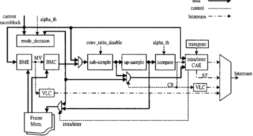
E. System Architecture
Figure 7 shows the system architecture of the shape coding. It integrates the optimized BME, CAE, Up/Sub-sampling units presented in previous subsections. In additional, some extra operations, such as mode decision, comparison, are also required to accomplish the complete shape coding. For boundary blocks, the full- path processing includes mode-decision, BME, size convert ratio decision, intra CAE and inter CAE. This totally requires 2305 cycles. For non-boundary blocks, however, only 23 cycles are required to encode the block type (decide block type and perform VLC). By applying pipeline scheduling, the block-sampling interval can be less than the full-path latency. It can be estimated that when a series of boundary blocks are encoded (worst case) the sampling interval takes 1105 cycles. Since the non-boundary block's execution cycles are much less than 1105, their execution time is hidden within the 1105 cycles. Assume that there are 3564 boundary blocks (30% of total blocks) to be encoded per second, all boundary blocks require full-path processing. Under the assumption, total execution cycles taken to encode a CIF 30fps binary shape sequence are about 3939420 (1105*3564+1200). Suppose that a video scene contains two VOs, by employing the proposed architecture running at 7.8MHz, the real-time requirement for the core profile level 2 specification can be easily achieved.
data ,-b
CO",rOl ___________.
bitsueam - - - . +
C
ma
Figure 7. Block diagram of system architecture for shape coding
IV.
Conclusions
An efficient solution for supporting object-based hnctionality of MPEG-4 Video from the algorithm and architecture level consideration is presented. Based on the analysis results of computational behavior for MPEG-4 Video Codec, it is found that most computation load is occupied by motion estimation and shape coding. The data-type optimization concept and data-reuse techniques are utilized to remove the bottleneck. The proposed algorithms and architectures can perform these tasks very efficiently so as to reach the target for the implementation of a real-time interactive visual communication system.
V.
Reference
ISOAEC JTC I/SC29/WGll, N2502a, Generic Coding of Audio-Visual Objects: Visual 14496-2, Final Draft IS, Atlantic City, Dec. 1998.
N. Brady, F. Bossen, N. Murphy,” Context-Based Arithmetic Encoding of 2D Shape Sequences“, Proc. of International Conference on Image
Processing (ICIP’97), ~01.1, pp.29-32, 1997.
H.-C. Chang and L.-G.Chen, “An efficient modeling architecture for real- time content-based arithmetic coding”, Proc. of SPIE VCZP ’99, ~01.3653 pp.708-715, San Jose, C.A, Jan. 1999.
D. Gong and Y. He, “Computation complexity analysis and VLSI
architectures of shape coding for MPEG-4”, Proc. of SPIE VCIP2000, vo1.4067 pp. 1459-1470, Perth, Australia, June. 2000.
H.-C. Chang, L.-G. Chen, M.-Y. Hsu, Y.-C. Chang, "Performance Analysis and Architecture Evaluation of MPEG-4 Video Codec System“, to be appeared in Proc. International Symposium on Circuits and Systems (ISCAS‘2000), May 2000.
T. Moriyoshi, H. Shinohara, T. Miyazaki, and I. Kuroda, “Real-Time Software Video Codec with a Fast Adaptive Motion Vector Search”, proc. of
IEEE Workshop on Signal Processing Systems, pp.44-53 1999.
L.-P. Chau, N. Ling, G. Hovden, H. Lan, H.-C. Ng, K.-P. Lim, “An MPEG-4 Real-time Video Decoder Software”, proc. of International Conference on
Image Processing(ICIP‘99), vol. 1, pp.249 -253, 1999.
J.-F. Shen, L.-G. Chen, H.-C. Chang, T,-C, Wang, “Low Power Full-Search Block-Matching Motion Estimation Chip for H.263+ Video Coding”, proc.
of International Symposium on Circuits and Systems (ISCAS‘99), June 1999.
K.-M Yang, M.-T Sun, and L. Wu, “A Family of VLSI Design for the Motion Compensation Block-Matching Algorithm”, IEEE Trans. on
Circuits and Systems for video Tech., Vo1.36, No.10, October 1989.
[lo] W. B. Pennebaker, J. L. Mitchell, G. G. Langdon, and R.B. A r p s , “An Overview of the Basic Principles of the Q-Coder Adaptive Binary Arithmetic Coder,” IBM Journal of Research and Developments, Vo1.33, No.
[ l l ] G. Feygin, P.G. Gulak, and P. Chow. “Architecture Advances in the VLSI Implementation of Arithmetic Coding for Binary Image Compression,”
6, pp.717-725, NOV 1988.
pp.254-263, 1994.